 Jorj Bauer
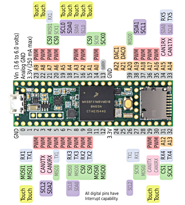
If you go take a look at the Teensy 3.6 pinout, you'll find that it has a bajillion I/O pins.
Wow.
When I first saw all those pins, I thought something along the lines of "that's great, but it's gonna be a nightmare if I ever actually need all of those." I wasn't entirely wrong, but it's also a godsend that they're all available.
The display eats up all of ports C and D - pins 2, 5, 6, 7, 8, 9, 10, 11, 12, 13, 14, 15, 20, 21, 22, and 23. It also needs its RS (16), WR (17), CS (18), and RST (19) wired up. 20 pins down.
The keyboard needs 13 columns wired up - pins 0, 1, 3, 4, 24, 25, 26, 27, 28, 29, 30, 31, and 32; and 5 rows - pins 33, 34, 35, 36, and 37.
That just leaves digital pins 38 and 39 unused.
39 I'm using for the reset/menu button, which I want to be separate from the rest of the keyboard. Eventually I'd like this to have some interrupt wired up. Or something. Seems like a good idea.
Pin 38, aka A19, is the battery input. Since the Teensy 3.6 isn't 5v tolerant on its inputs, and Li-Ion batteries go up to 4.2v when fully charged, a couple of resistors form a divider network to safely provide input here.
And now we're out of pins, but not out of peripherals to connect. What about the speaker?
Fortunately there are two 12-bit digital-to-analog pins! Ping A21 and A22, aka DAC0 and DAC1. I'm using DAC0. And now it feels like we're on borrowed time, having found an "extra" pin.
But we still have the joystick, and we're forced to decide which compromise to make.
The joystick needs two analog inputs. A22 is output-only. I could move something there as an output and reclaim one pin; and then move the reset/menu button in to the keyboard matrix, reclaiming another. I'm not liking that plan, but it's possible.
Or, we could look at the back side of that Teensy 3.6 pinout card...
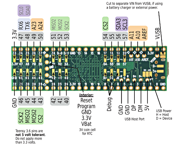
Look at all the bonus pins! All of those pads, just sitting and waiting for an insane person to try to do something like, well, maybe this:
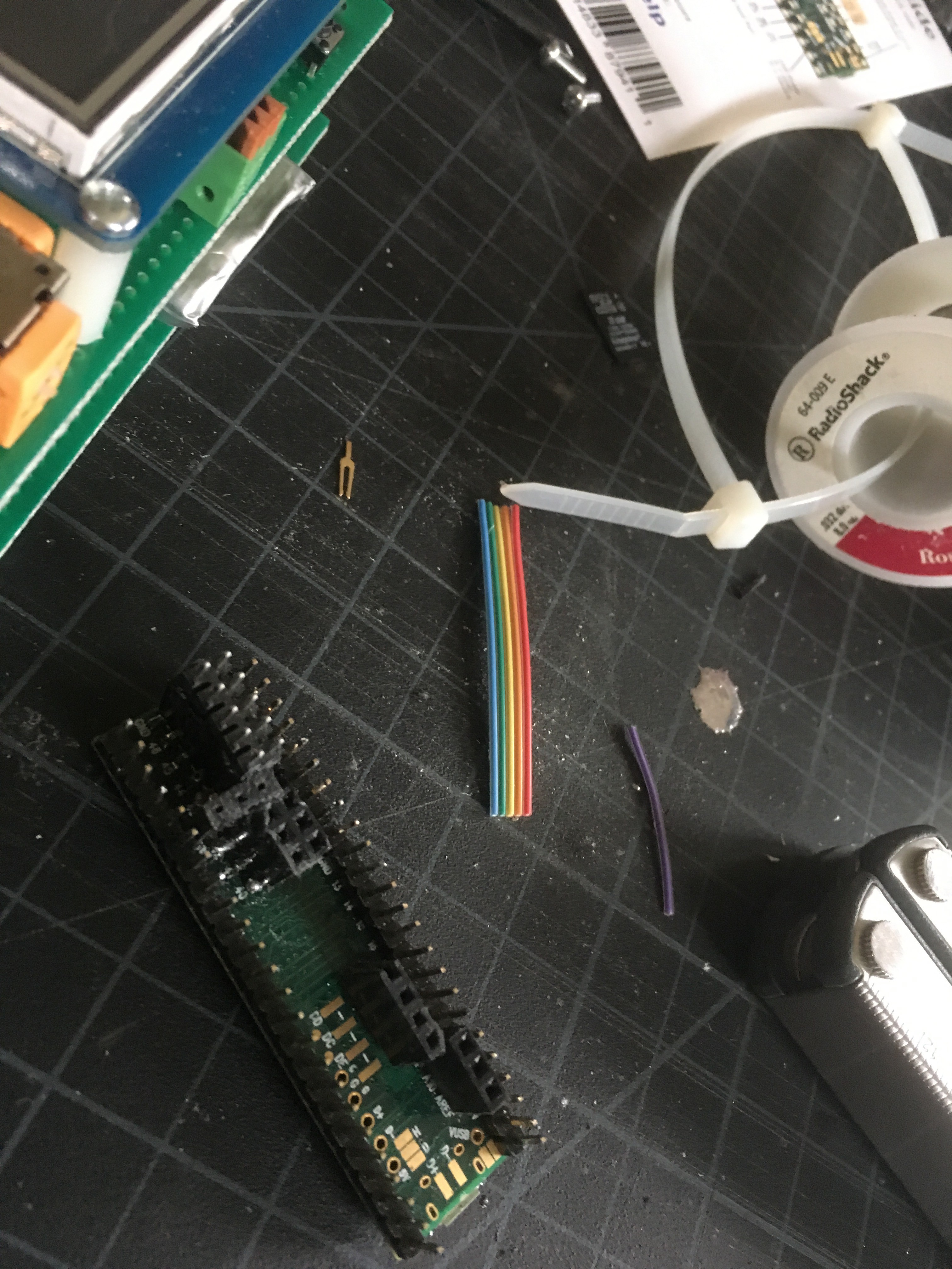
and this:
There were some casualties along the way. Because I was soldering in these pins after having put the other headers on the Teensy, there wasn't really enough room for the soldering iron. Some bits of plastic were accidentally melted; the pad for pin 54 was ripped off. But now we have a new lease on life! Extra pins everywhere.
The joystick gets A23 and A24. (I had originally put it on A10 and A11, but while troubleshooting the bad joystick problems I moved it.) And now we get in to insane-overtime-bonus-hardware-land.
I'd like to be able to interface this with, well, stuff. I have no idea what stuff. Or how. But I know that, when everyone was raving about the nrf24l01 last year, I bought two of them and stashed them to play with some day. So one of them goes in on pins 40, 41, 42, 51, 52, and 53. And a quick press-insert header sneaks under the edge of the LCD, giving me access to ground and pins 56 and 57.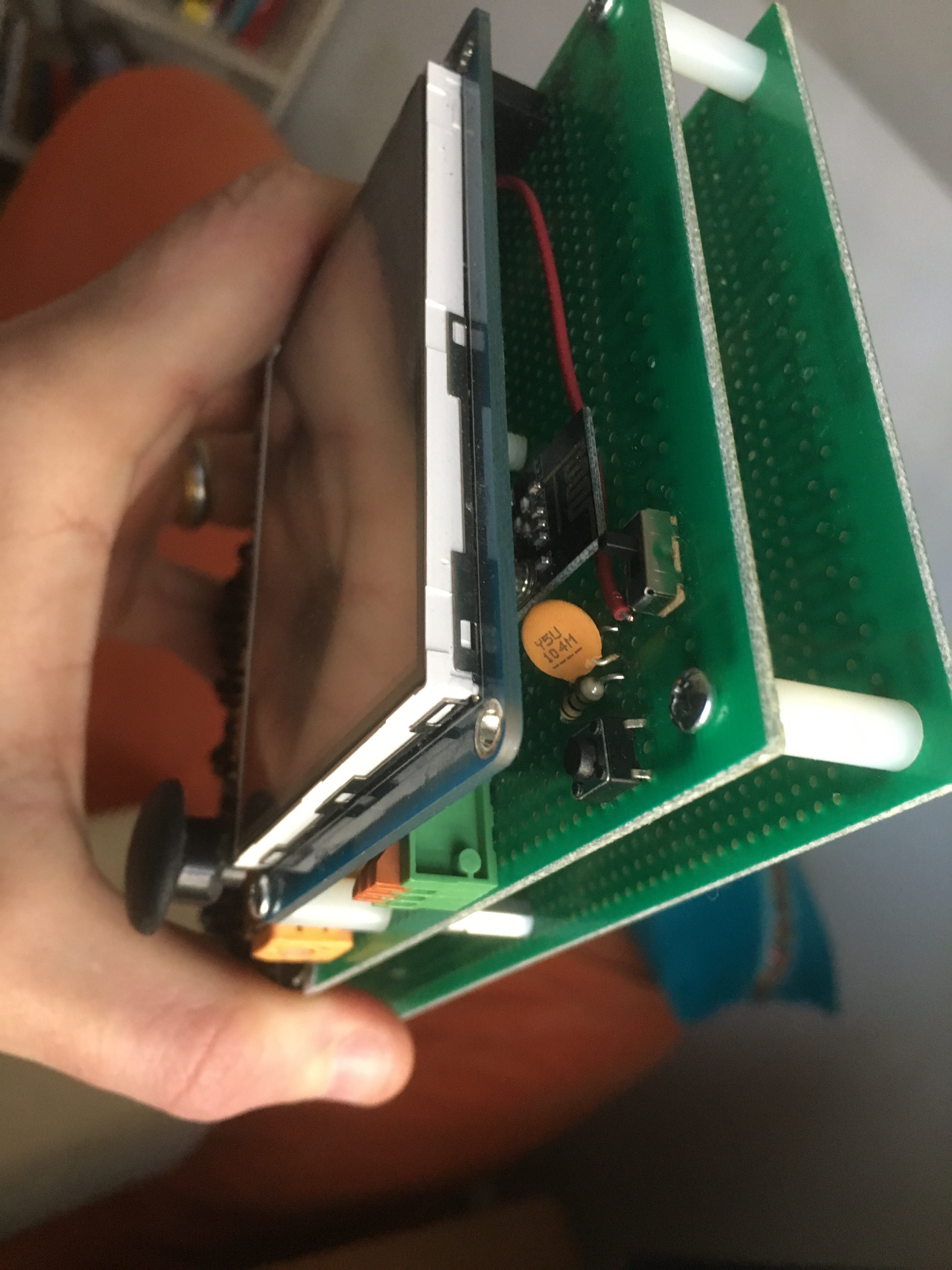
AND WE STILL HAVE ROOM FOR MORE. The Teensy 3.6 is a beast. Nicely done, Paul!
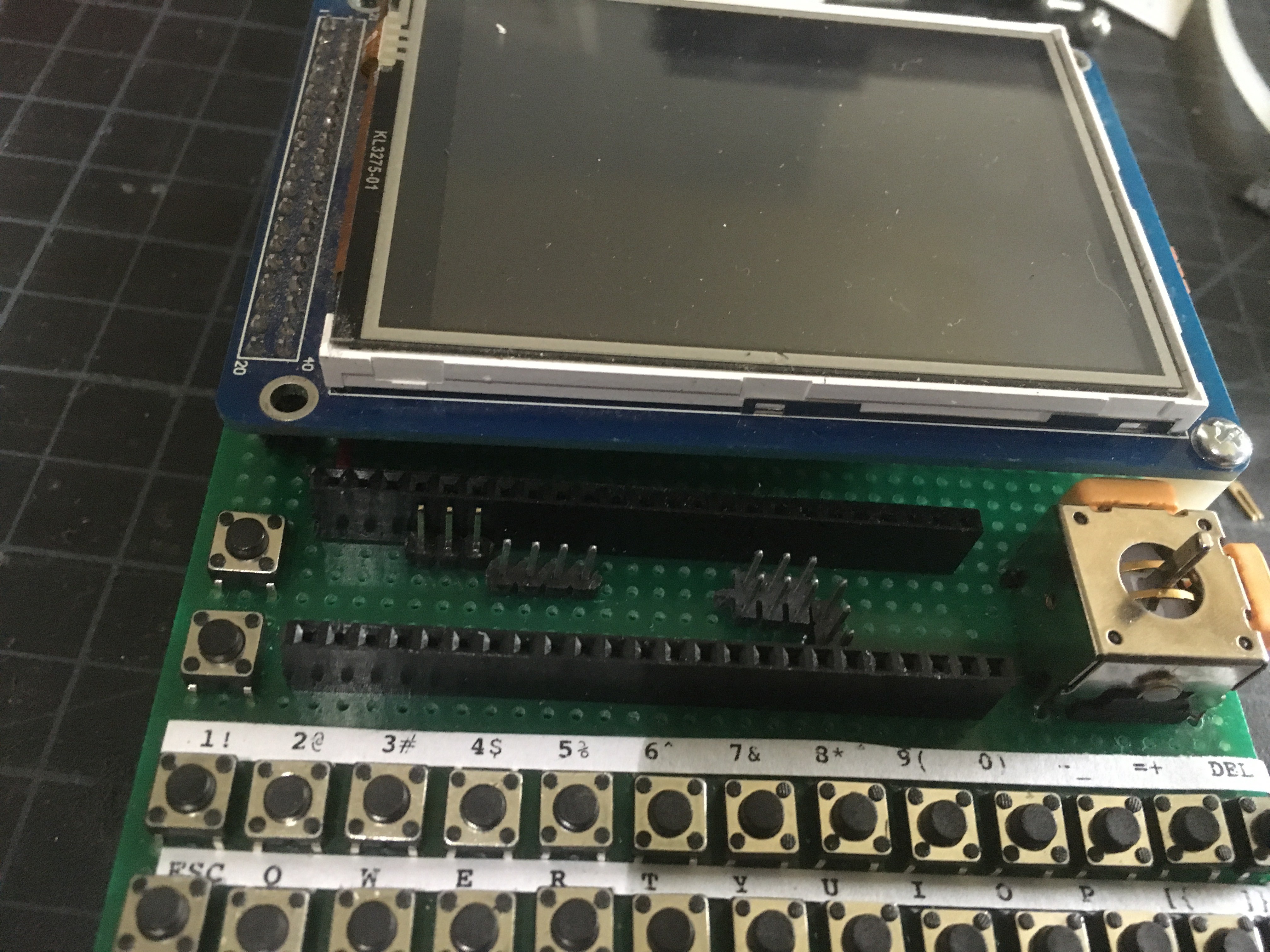
But this all comes at a price. The second board, and standoffs, were added to protect this:
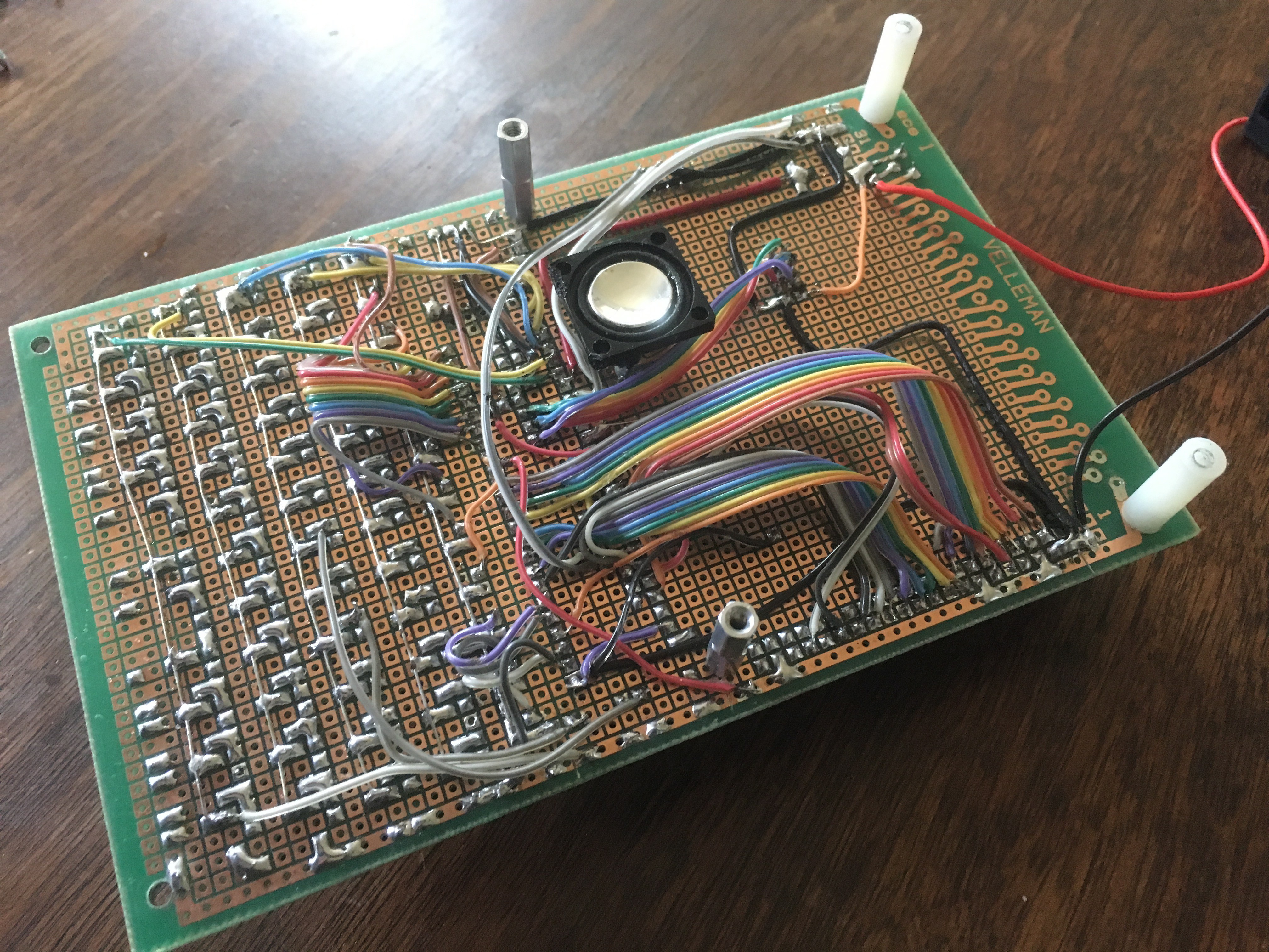
... so I took the botched first board, where I thought I was going to use that LCD interface - but found it unnecessary, threw the board in the trash and started over, and then rescued the trashed board when I needed a backplate. Because, y'know, nothing goes to waste? Or something. I figure it's good enough until I figure out what kind of case this will go in. (I'm not entirely sure that I ever will. It'll probably live its life like this, case-less.)

At some point I'll draw up the schematic and post it. And update the list of materials. Eventually. Don't hold your breath. :)
Discussions
Become a Hackaday.io Member
Create an account to leave a comment. Already have an account? Log In.