 M.daSilva
Any standard HAM radio exam asks for the building blocks of a simple transceiver, plus some details, to some extent.
I enjoy theory as much as the next guy, but I'd like to see how that applies in real life:
-How does a broadband amplifier behave at different frequencies?
-How to design such boards?
-If I want to modify my transciever to make it operate at different frequencies, how will I do it?
If you'd like a crash course on SSB radios, I can't recommend you enough this excellent HaD article series, written by Gregory L. Charvat.
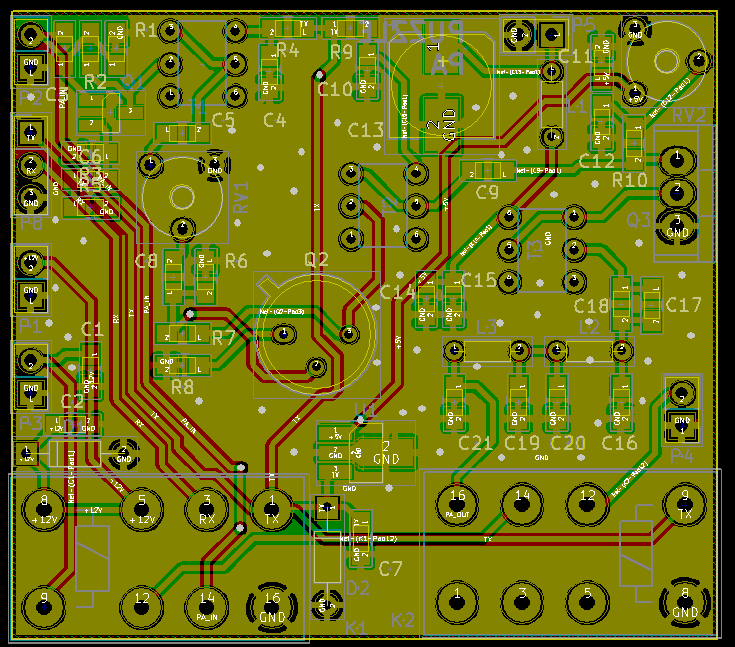
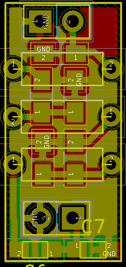
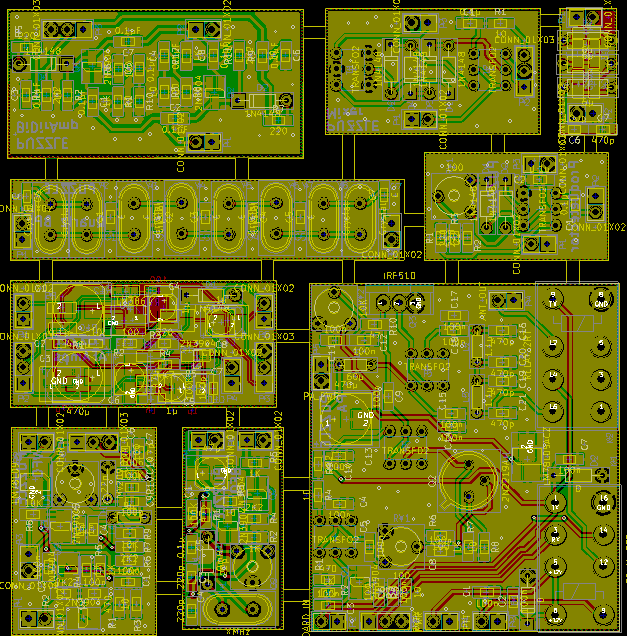
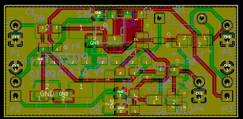
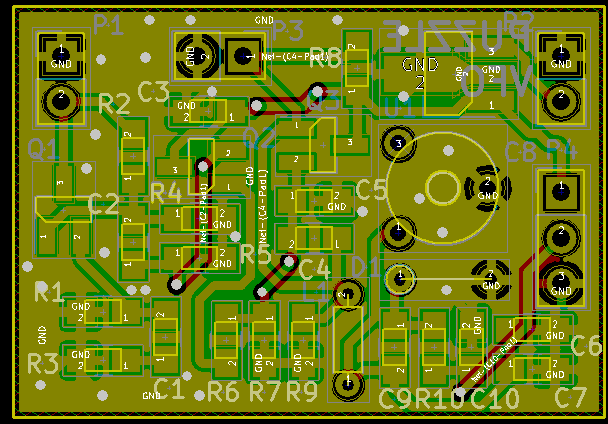
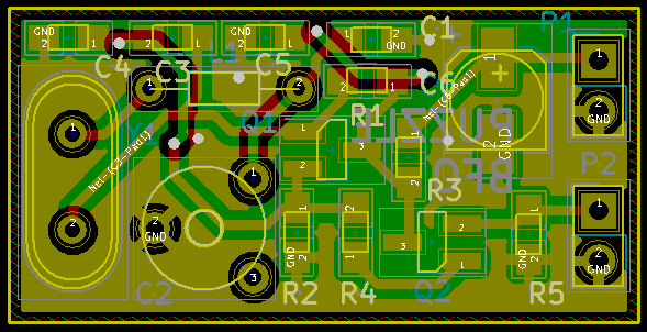
To answer those questions (and more), I'm making boards for all those building blocks:
-VFO
-BFO
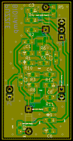
-RF amplifier
-Power amplifier
-Audio amplifier
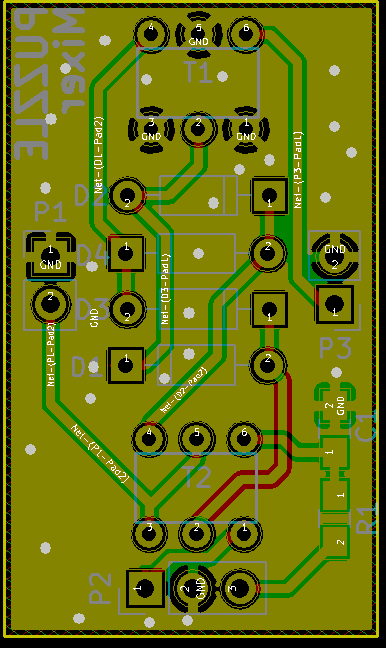
-Mixer
-Product detector
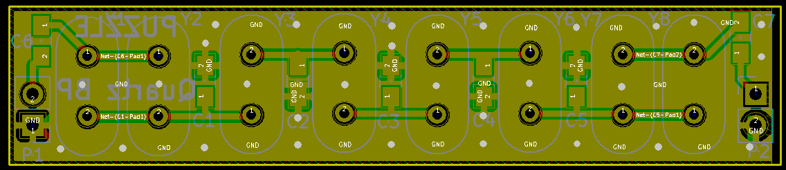
-Quartz filter
-BandPass filter
Now, this is not going to be my own work at first: I'd like to first replicate a very well-known design of transciever: the BitX, designed by Ashhar Farhan. That'll give me the opportunity to build something I know should work, then start modding from there (and hopefully learn something along the way)!The boards will be a mashup of Farhan's BitX40, Minima and BitX20; which would allow me to quickly swap the modules out to change the radio's final behaviour.
The aim is to build a working single-band, single-conversion SSB transceiver, and work form there, modify it to expand its capabilities.
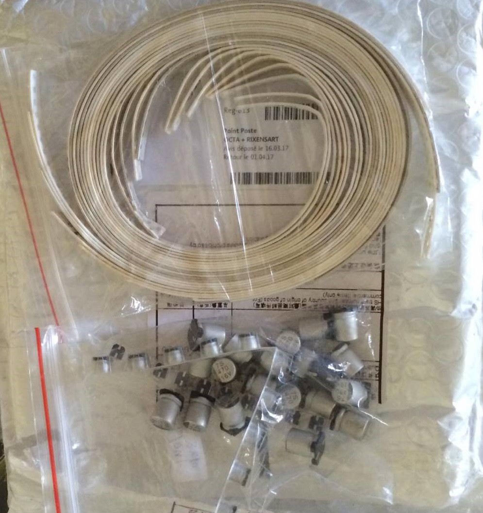
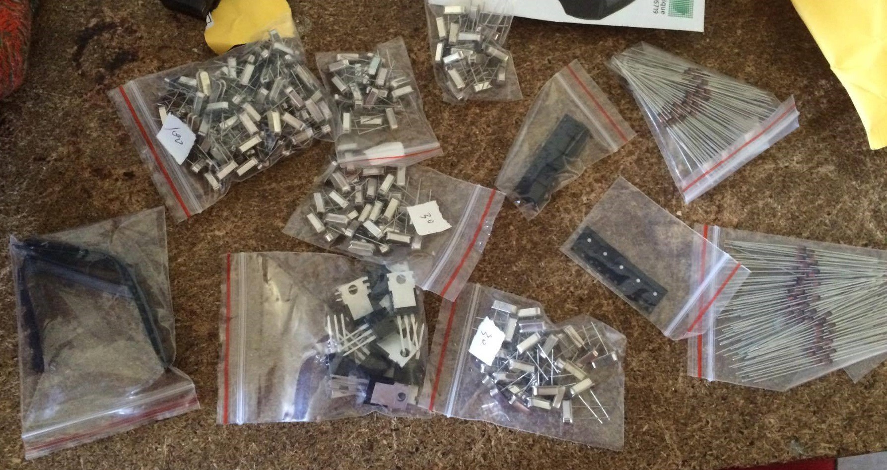 And this showed up the other day!
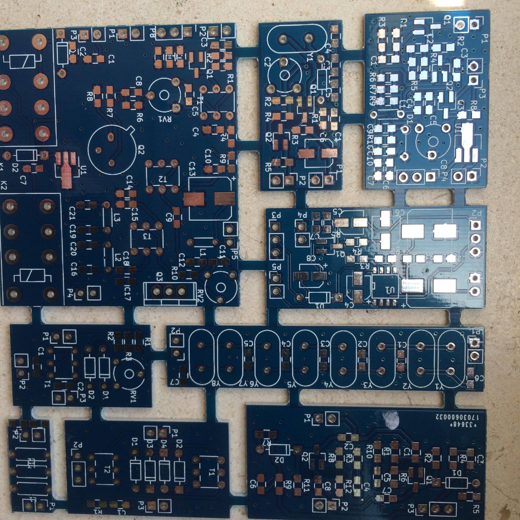
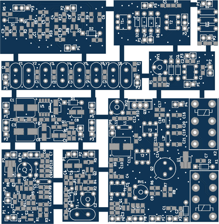

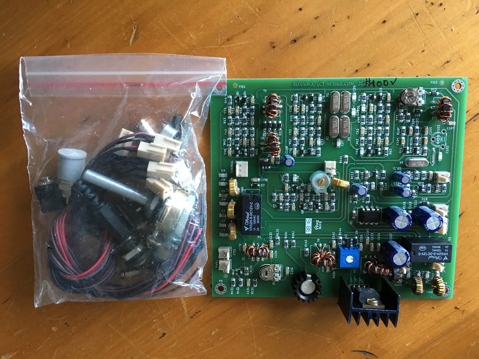 One of these kits is on the way; I'm sure I'll have lots of fun playing with it. However, I don't want to stop there, I feel like this transceiver could be easily modified: change the IF frequency, turn it into a biband/multiband transceiver, ... As I don't want to risk ruining this nice board, and I want to learn some more, I'll respin my own! To help me understand how each block works and interacts with the others, they'll be divided into units I can play with individually.

 Capt. Flatus O'Flaherty ☠
 rodrimen
 Davide Ercolano
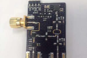
Do you have the BOM somewhere?