Jac Goudsmit
-
A Quick Update
02/05/2022 at 02:12 • 0 commentsI know it's been quiet in this corner for a long time. But lately there have been some exciting things happening to this project. So here goes!
![]() ---------- more ----------
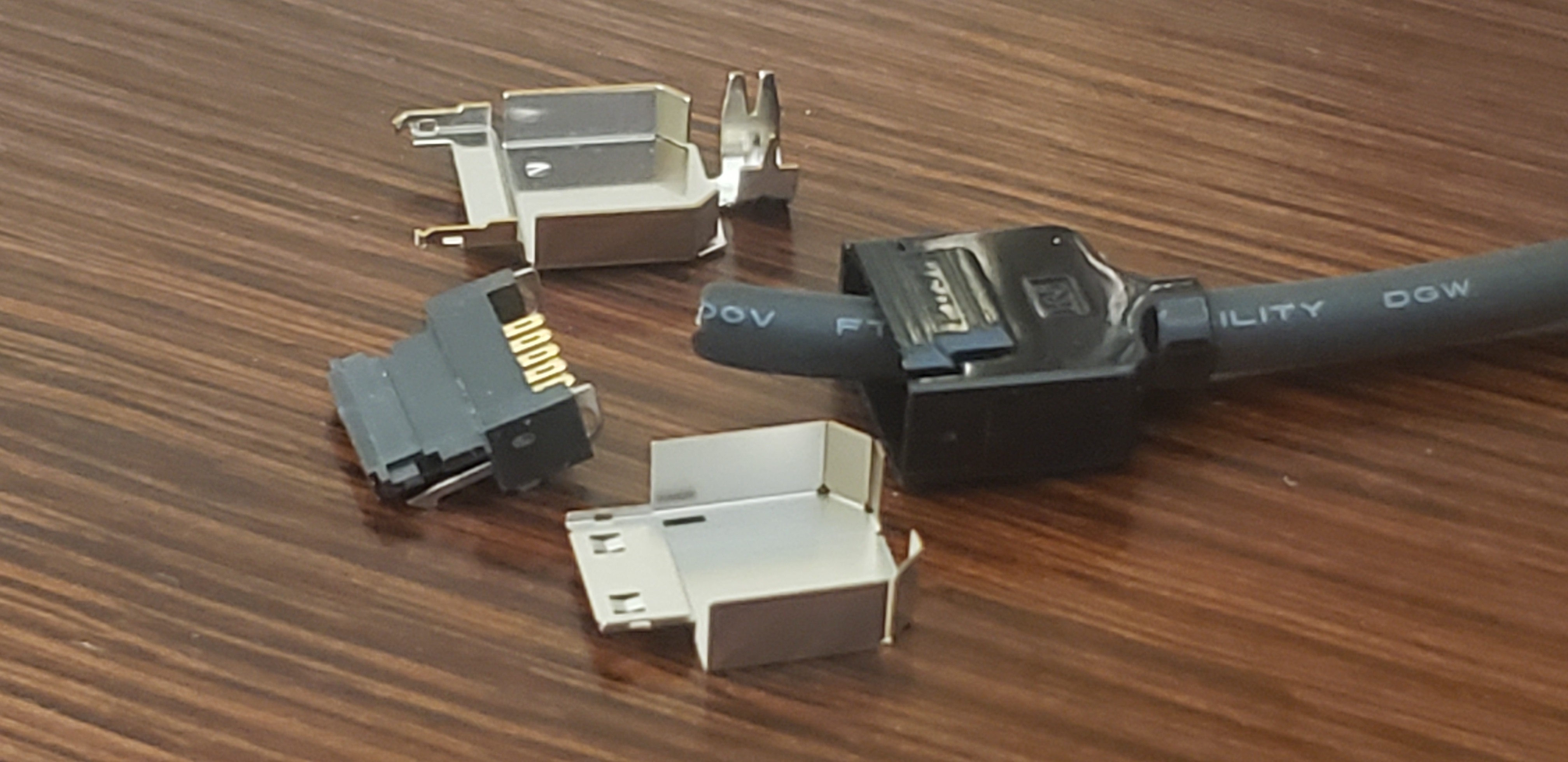
---------- more ----------First of all, the most exciting news: I found a cable that fits the connector! As I noted in a previous post, the connector that Philips used for the back of the DCC-175 recorder, is not a custom connector; it's made by Hirose and is still in production at the time of this writing, and available from big online Electronics retailers -- or at least some of them: Currently Mouser has them but DigiKey is out of stock. But the connector only allows attaching a cable with an outer diameter of up to 5.4mm. After I bought a $400+ spool of cable a while ago which was 5.9mm OD, I found out that yes, that really is a hard limit.
Enter the Tensility 50-01540 cable which is available from DigiKey in various lengths, for about $10 per meter: It is the correct diameter, it's shielded and it has the same conductor isolation colors as the Philips cables.
Unfortunately the Tensile cable appears to be a lot stiffer than the Philips cable. I'll have to put one together to see how well it's going to work. I may decide to make my cables a lot shorter than the Philips cable.
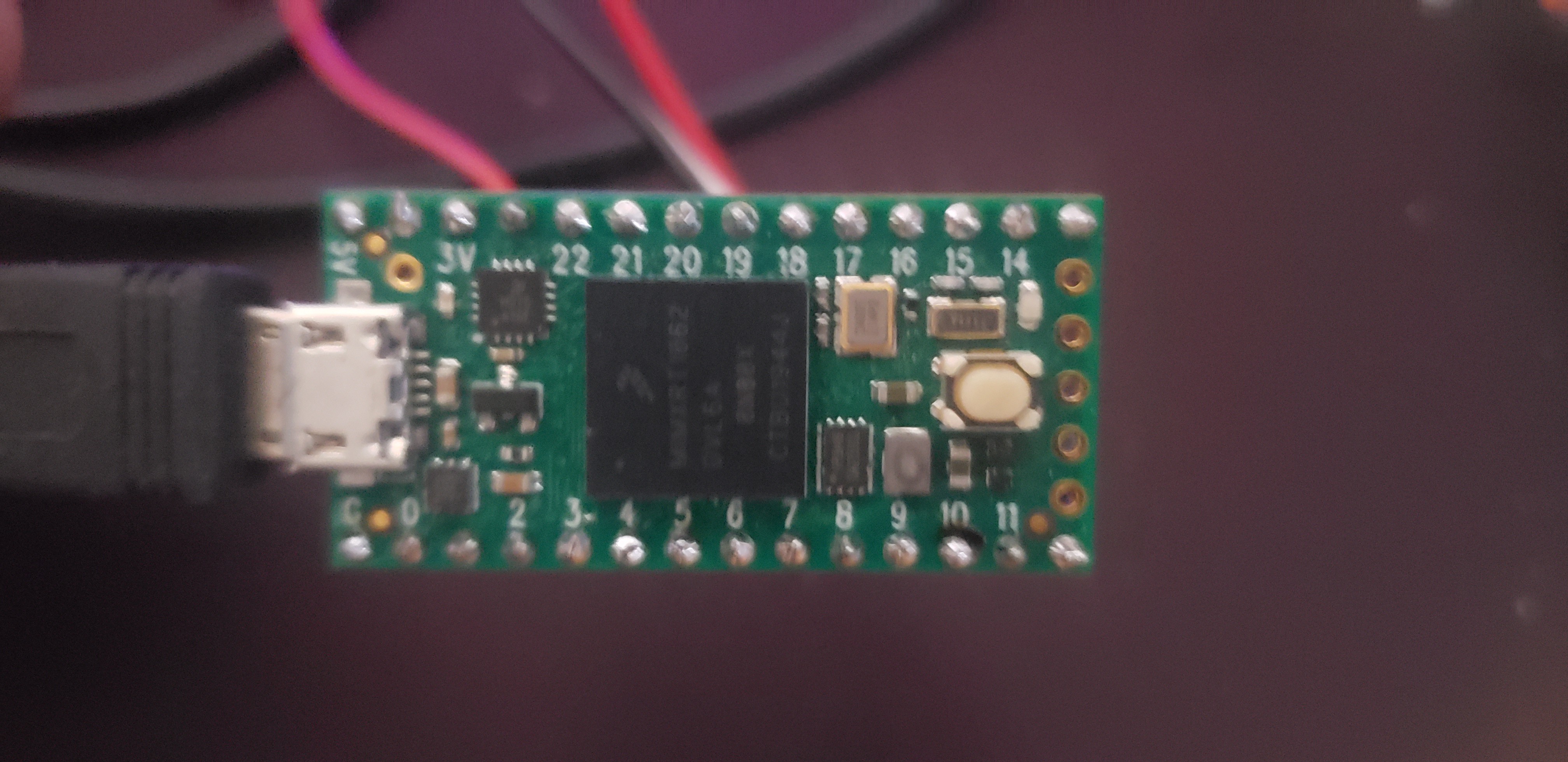
Change of Venue: Teensy 4.0
I'm a big fan of the Parallax Propeller. Almost all projects that I have on Hackaday.io use the Propeller 1. But the Propeller also has disadvantages. For one thing, while it's great at doing low-level stuff, it always takes an incredible amount of work to do something complicated, fast. For example, it took me a lot of time to write my Propeller-based SPDIF receiver, and I had to jump through quite a few hoops to make it fast enough, programming in Assembler. And it still doesn't automatically detect the speed, and won't work at 48kHz without overclocking because I was just a few cycles short to process the bits fast enough.
I already decided that for this and other projects, I would probably switch to a Teensy. For this project at least, the Teensy of choice is the Teensy 4.0. It has many advantages:
- Costs less than $20 at the time of this writing
- Amply available from many retailers in spite of global chip shortages
- ARM Cortex M7 based microcontroller at 600MHz
- Plenty of on-board ROM and RAM
- Lots of Serial ports, SPI ports, I2C ports
- Connects to host via USB, but also supports its own USB host port that I might use for e.g. a keyboard.
- Great support for audio: multiple I2S ports and native SPDIF transmit/receive support (it should even be capable of partially decoding the ITTS information from 1st and 2nd gen DCC recorders). The USB port can be configured as audio device, and an Audio Library can be used to do things such as play audio from the PC to the SPDIF output.
- Other goodies such as a Real-Time Clock and a fast SD-card interface.
The only disadvantage really is that it's not 5V tolerant.
![]()
Looking Forward
So where am I, and where am I going?
If you followed the project, you already know that the L3REF pin on the connector generates a pulse at the beginning of each Tape Frame, and that each Tape Frame contains 8192 bytes of PASC data which is on the I2S bus. The PASC data is compatible with MPEG 1 Layer 1; however, unlike MP1 encoders, PASC doesn't encode (nor accept) any data in the padding slots that are generated at 44.1 kHz.
The synchronous serial port on the connector is basically compatible with SPI Mode 3 (idle high, sample on trailing edge, LSB first). There are 12 blocks of 32 bytes of serial / SPI data per Tape Frame; 3 x 32 bytes per Tape Block. Thanks to the comments of follower @Vick we also know that those data blocks from the recorder contain (A) 28 bytes of status information plus 4 bytes of AUXINFO, (B) 32 bytes of remaining AUXINFO and (C) 32 bytes of SYSINFO, respectively.
That means that I now theoretically have enough information to generate tape dumps (including timing information and ITTS text information) using the DCC-175.
1. Implement SPI Slave Mode
I'm currently working on writing code for the Teensy 4.0 to use the SPI ports in Slave mode. The standard SPI libraries that are provided with TeensyDuino only support Master mode, and that's not good enough: The SPI clock is provided by the recorder.
2. Connect the Teensy to the DCC-175
Once I have the SPI functionality working, I'll connect the Teensy 4.0 to the Turkey Lab. At first, I'm going to grab the SPI data, and see if I can figure out what those 28 bytes of recorder data are. The L3REF signal will probably be used as CS signal for the SPI port, so that I can easily synchronize the SPI data with the tape frames.
3. Reverse-Engineering the Last 28 Bytes of the SPI Messages
Then I'm going to analyze what the DCC-Studio program sends to the recorder to make it do what it can do. This is a matter of connecting the SPI receiver line on the Teensy to the Transmit line from the Win98 PC to the recorder. The Teensy 4.0 has a cool feature to use it for "sniffing": It can either swap the SDI and SDO line or it can switch both SDO and SDI to input more or output mode.
Once this is done, I should be able to connect the Teensy directly to the DCC-175 without the need to connect the Windows 98 PC. I'm really looking forward to this!
4. Receive I2S
Then it's time to send and receive some PASC data over I2S. I'll probably start by dumping I2S data from the recorder to the CDC serial port, along with the SPI traffic.
At this point, the setup can be used to dump tapes to a PC, which can store them on hard disk, e.g. as MKA file or MP1 file (without AUXINFO/SYSINFO). It will be possible to play those files on a music player on the PC.
5. Transmit I2S
At one point, it will be possible to send AUXINFO and SYSINFO to the recorder while recording PASC. I suspect that this is fairly easy once we get to this point. I hope that it will be possible to send a tape dump file to the recorder which will theoretically make it possible to record a tape that's formatted as a prerecorded tape. That will be an important milestone!
6. SPDIF
Meanwhile, I will also be working on SPDIF input and output. In the DCC Museum forums and on Facebook, we've had a lot of questions from people who want to record their own DCC's from files they have on a PC. This should be fairly easy to do on the Teensy 4.0 by adding TOSlink and coaxial connectors. Using the Teensy as SCMS defeater should be cool.
7. Other Ideas
There are also things that I still want to do with the DCC-730/DCC-951. For example I want to replace the front panel by a color LCD screen and add VU meters. I also want to make it possible to enter song titles via a keyboard.
Furthermore, I think it would be great to store DCC dumps on MicroSD card.
Another idea is to read ITTS data from a 1st or 2nd generation recorder, via SPDIF. I may make it possible to copy ITTS information from one recorder to another (this would involve storing the data on SD card, and recording a prerecorded-formatted tape from the SD card).
So many ideas, so little time...
-
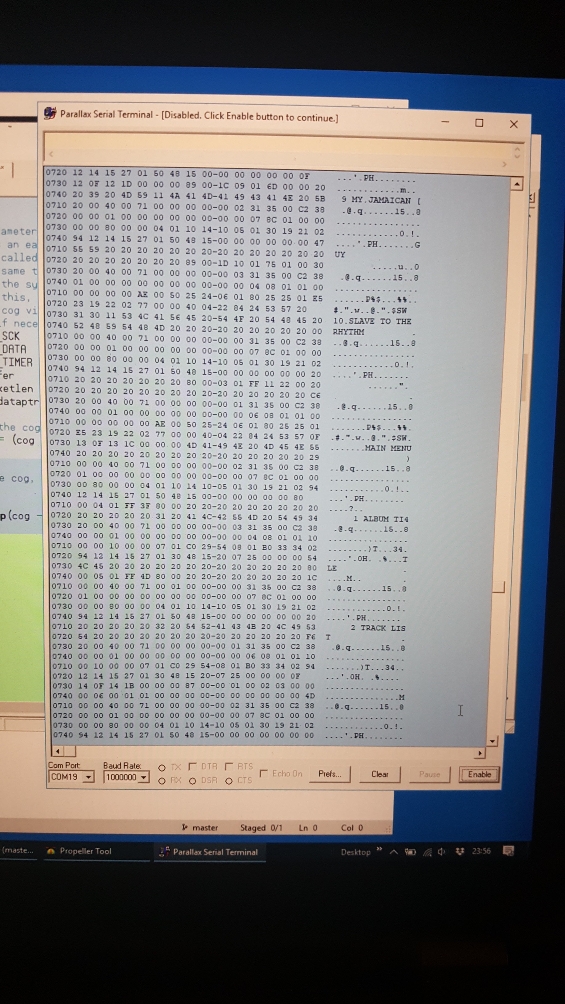
Exciting News: Incoming Data!
02/16/2019 at 08:21 • 2 commentsI fixed a few problems in the Synchronous Serial capturing program that catches the output of the microcontroller in the DCC-175, and behold: this was scrolling up my screen while I was playing my Grace Jones - Island Life prerecorded cassette!
![]() ---------- more ----------
---------- more ----------Not So Fast!
Okay, there still seems to be a problem where every once in a while it misses a byte. I don't know why this happens, it could be interference. I'm sure my non-shielded wires don't help, and it's possible that, even though output buffers are used for the output lines in the DCC-175 computer connection, they might not generate enough current in some cases to draw the Propeller inputs low or high. Or maybe there's something that I can do about my timing parameters to prevent this.
Try the Veal: Wait, There's a Menu???
The titles of the last two songs on the cassette are clearly visible (and so was the rest of the track list): "9 MY JAMAICAN GUY" "10 SLAVE TO THE RHYTHM" but there's more to see here: "MAIN MENU" "1 ALBUM TITLE" "2 TRACK LIST"...
Those last texts would have totally bewildered me a few years ago. What is this strange information that looks like it's an interactive menu, and why is the DCC-175 sending it to the computer?
The answer is that this is the Interactive Text Transmission Service (ITTS) data that's stored on every prerecorded tape. Prerecorded tapes usually mention this on the J-card: they tell you they contain "DCC-Text" data that can be shown on TV if you have a compatible DCC recorder. No such recorder was ever available to consumers, but Philips made prototype ITTS decoders that could be connected to early DCC recorders to show the information so that mastering facilities could verify that the DCC-Text information showed up as expected.
The ITTS information is formatted according to the ISO-61866 standard. I have a copy of that standard, and it's expensive and big. I can't share the standard here because of copyright, but as I understand, the way that the data is formatted is similar to CD-Text. I strongly suspect that there are lots of things in the standard that existing prerecorded DCC tapes don't use, but because the recorder basically only acts as a device to pick up the information and spew it out to a decoder, the standard can be any size and there can be any amount of features, and the recorder couldn't care less. Making a decoder for ITTS is probably difficult (and that might be why Philips never went through with it) but it's not impossible. It may happen one day, but that's a whole different story.
Decoding All the Bits
The DCC Museum recently found a PDF online that might help with decoding the data. The document is called "Technical Guide Volume 31: Auto DCC Technology" and it pretends to be a service manual for the Panasonic CQ-DC1 car stereo system with DCC mechanism, but contains a HUGE amount of information about the inner workings of DCC, probably copy-and-pasted from the DCC specifications. And it looks like Page 27 has information about how various information such as time codes and song titles are stored in the AUX track. This could be the Rosetta Stone that could help me decode the information that the microcontroller spits out, but I expect that there's more about the data format of the synchronous serial port, since it also gives the computer information about the state of the mechanism (Play, Stop, Wind etc.) and possibly other things.
EDIT: The DCC System Description, donated to the DCC Museum, contains the official information.
Lather, Rinse, Repeat
When I look at the myriads of data scrolling by on my terminal emulator screen, there are a few things that stand out:
- When playing a self-recorded cassette, there is almost no data at all: Most bytes from the recorder are zeroes. When there's a marker (recorded with the DCC-Studio program), I can see the song title scroll by but then it gets mostly quiet again. It's like the Borg were all told to go to sleep and the voices get really quiet
- It appears that when the recorder has nothing to report, it just sends the same data over and over. Obviously this is by design. Probably the microcontroller sends a designated buffer based on interrupts and/or timers, and that part of the code doesn't have time to decide whether it already sent something. On the other side, the PC can probably detect where the data belongs "in the big picture", and stores anything it gets. It reminds me a bit of how Teletext works/worked: TV's would just show the lines of the selected page but all pages would be transmitted by the TV station continuously.
- It's not clear where data begins and how long the blocks of data are. I already know that data is transferred in packets of 32 bytes but it looks like those packets are grouped together. But just like other things in the world of DCC, things don't necessarily make sense at all levels; for example you might expect that packets are in groups of 4 because there are 4 tape blocks to a tape frame, but no. This will take some research. EDIT: There are 12 blocks of data in each tape frame, with 4 times a group of 3 packets containing 28 bytes of recorder data, 36 bytes of AUXINFO and 32 bytes of SYSINFO. Thanks Vick for pointing this out in the comments!
So Where Am I Going?
The dropped bytes are a potential problem, I should figure out what goes wrong there. Maybe the recorder really is sending fewer bytes sometimes? Is it an electrical problem? Maybe the tape I'm using is too damaged or my heads weren't clean? I should try cleaning the heads and try some other tapes to see if the dropped bytes can be eliminated.
As for the repeating data, I wonder if it would help to detect the L3REF pulse in my Propeller code. That might let me know where the start of the data is.
In order to follow the data from the recorder to the PC as well as the data from the PC to the recorder, I need to run two instances of the sync serial decoder. But the data stream for each line (TX and RX basically) runs at a pretty high speed, and generating a hexdump generates a lot more serial traffic than just sending the bytes in another way. I think if I interleave the transmit data with the receive data, it will make things very confusing very quickly, and I would be practically begging for flow control problem (because there is no flow control) if I would keep doing things in Hex.
So I think it would be better if I send the data out from the Propeller in binary or (slightly more friendly to the eyes) Base64 or something. That way, the stream has a much better chance of arriving intact, and that way I can write a C application under Windows to help me decipher the data. I'm thinking for starters I'll write a console application that hexdumps the data in a much wider format than 80 characters, so that I can get a feeling of where the fields are in the data that gets repeated all the time.
In the next log, I hope I can show some results of my analysis.
-
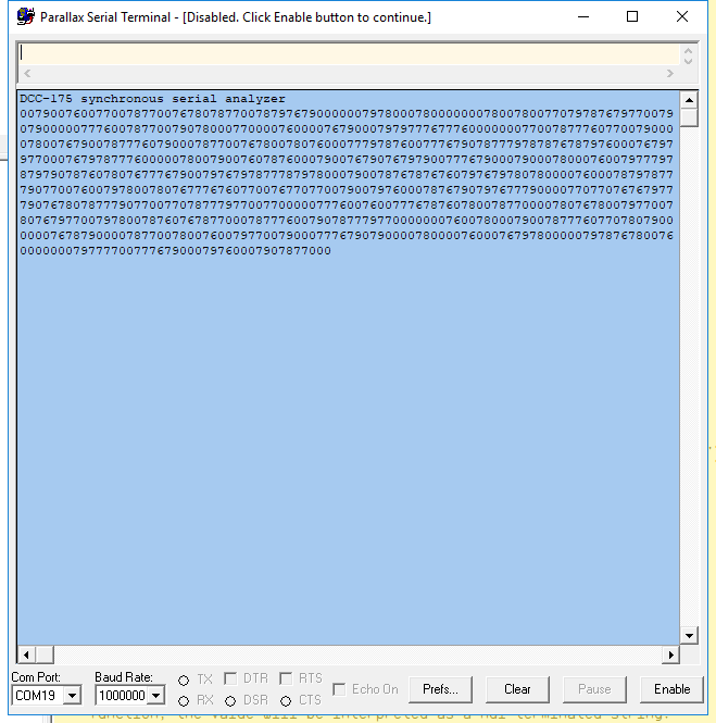
First Signs of Life from the Analyzer (Update: Now in Hexadecimal!)
01/22/2019 at 08:46 • 0 commentsI finally had some time to work on the Propeller software that interprets the synchronous serial data. The data in this picture are definitely completely wrong but at least the synchronous serial analyzer cog is generating data. For one thing, the Windows 98 computer was off during this first test and I don't know if the DCC-175 even talks to the chip in the DCC-Link in this state. Also the output format doesn't make sense: it should show a hexdump with lines that start with a memory address, followed by hexadecimal data, followed by filtered ASCII characters.
![]() ---------- more ----------
---------- more ----------There was another problem that I solved a week or two ago if I remember correctly. If I connect the recorder to the Propeller with no hardware in between, and the Propeller doesn't have any power, the residual impedances in the Propeller are enough to send a tiny amount of current into the WAKEUP line -- enough to make the microcontroller power up the recorder.
That would mean I can't leave the Turkey Lab powered while I'm not working on the project, because even if the Propeller isn't plugged into the development computer, it would keep powering up the recorder, and I want the recorder to stay in Standby when I'm not using it.
Additionally, the microcontroller in the recorder apparently doesn't check for the WAKEUP signal when it's powered on (so that answers the question what WAKEUP does during operation: Nothing). So once it's on and sits there, twiddling its thumbs (after it's straightened out the tape during startup), it waits for a few minutes and then turns itself off, and then immediately on again.
The fix was to put a resistor in series with WAKEUP. I did some experimenting and it turns out with a 10K resistor, the Propeller can still reliably wake the recorder by making WAKEUP high, and when the Propeller is not powered or when the Propeller holds the pin LOW, the recorder doesn't switch itself on.
Anyway, the next step is to debug the software until I get something sensible on the serial terminal. At least it's producing SOME data, and the output is definitely caused by the synchronous serial port parser: it's the only thing that generates commands for the TXX module after the banner message.
So once again, not much news but I'm making some progress now.
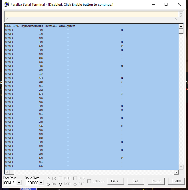
Addendum: The Hexdump Command Is 2, Not 8
As I suspected, I was sending the wrong command to my TXX module to generate a hex dump of the incoming data from the recorder: I had the input mode and output mode fields mixed up in the command, so instead of sending a command to generate a hexdump, I was sending a command to print a decimal representation of a 16-bit value. Yeah, not what I wanted.
Now that's fixed, it actually dumps packets from the microcontroller in the recorder! Well... Sort of.
![]()
As you can see, it clearly uses two buffers: one at location $0704 and one at $0724. But it only decodes one byte from the data stream per packet, and I'm scratching my head as to why...
The good news is that the data looks legitimate. The above data that looks wildly random, was generated while the recorder was playing a tape. When the recorder is in stop mode, the data seems a lot less random and a lot more repetitive. Once I find out why the code thinks each packet is only one byte long, I'll know more.
-
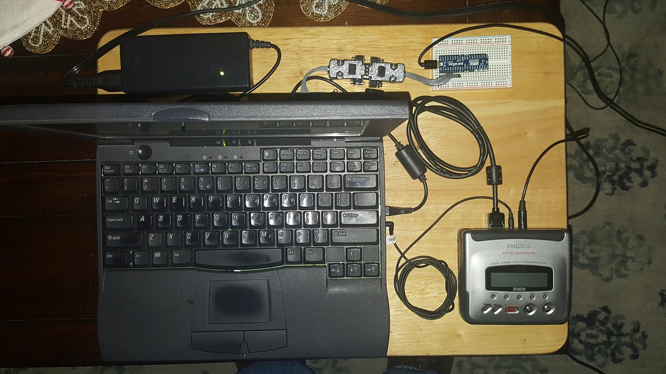
The Turkey Lab
12/25/2018 at 05:11 • 0 commentsA quick update to show off the "Turkey Lab", so named because I attached all the parts of the project to the bottom side of a cutting board that we used for cutting the Turkey on Thanksgiving Day until now. I used double-sided adhesive tape so that I can eventually detach everything again. At least I hope so: when I used the same tape to put blacklights on the wall for a Halloween party, it took parts of the wall with it when I tried to take the blacklights down again. Because of that, we now refer to this particular type of tape as Evil Tape in my house. So I suppose this must be a picture of the Evil Turkey Lab then ;-) .
![]() ---------- more ----------
---------- more ----------With all the components together in one place, it will be a lot easier to set up the hardware whenever I want to work on the project, and quickly take everything down again when the parking permit on the coffee table expires.
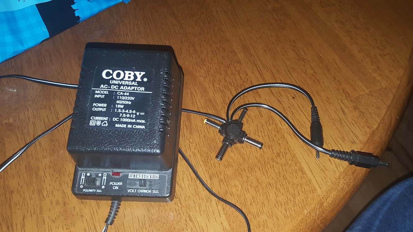
Interestingly (or not), both the DCC-175 and the Dell Latitude CPi-A 300 were made for use in 220 Volt Land (now known as 230 Volt Land). The computer is okay with 120V (I got an American power cable for it many years ago when it was still my main computer), Unfortunately the wall wart power supply for the DCC-175 is linear, so it's strictly 220V only and doesn't fit in an American wall socket. I previously used an American wall wart for it but unfortunately it has given the ghost. Rest in piece you crappy multi-transformer-tap non-stabilized linear piece of Chinesium with questionable parts. You've been useful but it's time for a replacement.
![]()
I ordered a switch-mode power supply that will replace it, but it won't arrive until later this week. Until then, I'll have to use the original DCC-175 supply from the Netherlands, and my step-up transformer which weighs almost as much as the entire Evil Turkey Lab.
I hope to find lots of time to work on the project this week and next week because I took days off from work, but with Christmas and New Year it's possible that this is going to get pre-empted again too.
Oh, one more thing: My friend Ralf "Dr. DCC" from the DCC Museum found an interesting document on the Worldwide Web with lots of low-level information about how DCC works. At first glance it looked like "more of the same" but it actually contains a lot of details that were previously unknown to us, such as how tape is formatted and what's inside the AUXINFO channel. That document will really help move things along with this project too. Thanks Ralf!
-
Good News! No News.
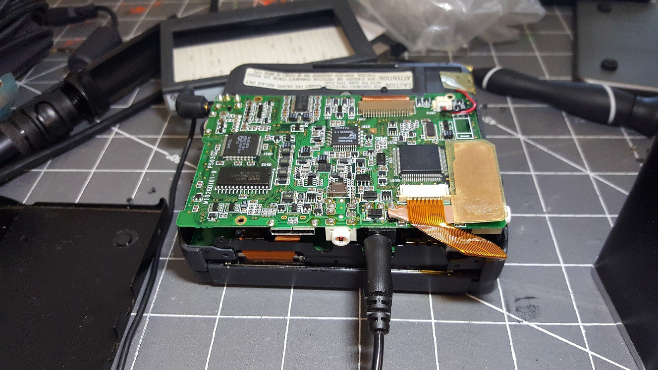
11/25/2018 at 23:01 • 0 commentsThe other day, I wanted to do some work on this project again after it had been put away for a while. But to my surprise and disappointment, the DCC-175 that I was using for the project before, had completely stopped working. Normally when you push the Play button (or Rewind or Fast Forward), a DCC-170 or DCC-175 shows a message on the screen saying "Power On". But the screen stayed blank.
This was depressing, because I got this DCC-175 a few years ago, after my first 175 stopped working in pretty much the same way. I couldn't find the problem in the first one, and I was afraid I would have to start looking for another replacement on eBay, and they are getting really rare. But then I thought: Maybe I should try connecting it to the computer and power it up that way? As you can see below, that idea wasn't totally successful but also not a complete failure.
---------- more ----------The power-on animation that gets quickly preempted by the Power Off message is actually a good sign: at least the microcontroller is still working; there must just be something that keeps it from starting when you try it without computer.
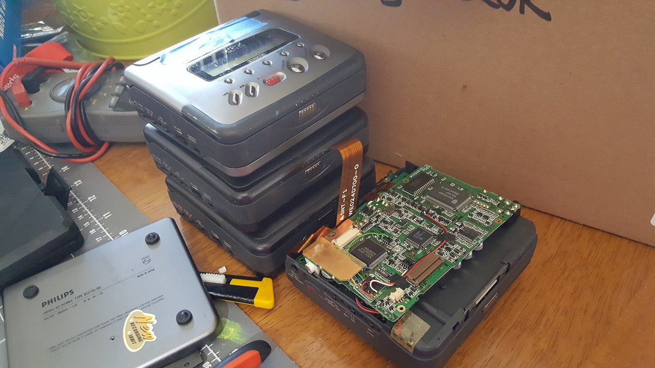
Troubleshooting with Redundancy
My friend Ralf ("Dr. DCC") suggested exchanging the top PCB of the DCC-175 with a (known working) PCB of one of my DCC-170s. The DCC-170 and DCC-175 are very similar, and all the electronic differences are on the top PCB. Everything else is exactly the same between the two portable recorders, except for some minor mechanical differences like the opening in the back side for the computer port. Exchanging the top PCB would narrow the problem down so I'd be able to tell if the problem was on that PCB or elsewhere.
That was a good idea! There was only one problem: I had 5 portable recorders (2x DCC-175 and 3x DCC-170) and as far as I knew, none of them was in working condition. I decided "now" would be a good time to find out what the actual status of each of them was.
![]()
It took me all evening to open each recorder and test which parts of which recorders were still good. I even went through the tedious task of inspecting the belts of each recorder, which is difficult because you have to desolder the motor, solenoid and detection switches, and if you're not careful you can break things and your recorder will never work again. I won't bore you with the details but the end result was that I found out that:
- The top PCB of the recently deceased DCC-175 worked fine when mounted in one of the working DCC-170s. Awesome! That meant that it would definitely be possible to get the 175 working again, even if I would have to replace the bottom PCB with another one from one of the 170s, and therefore lose one of my DCC-170's in the process.
- The top PCB of that DCC-170 didn't work with the recently-deceased DCC-175 chassis (at least at first) but worked great on its own chassis.
- The top PCB of my old, first DCC-175 (bought on the first day that it was available, in November 1995, which I believed to be unfixable), also worked on the chassis of a DCC-170! That means that if the "main" DCC-175 really does go bad, there's a good chance that I can still make my old DCC-175 work.
- After I inspected and cleaned the switches of the mechanism in the "main" DCC-175, it worked again too!
I couldn't get all recorders to work, because I stripped a screw in one of the DCC-170s, making it impossible to take it all the way apart (my Dremel and I would have to take care of that later), and because the belts or electronics in two DCC-170s were bad. Also, the PCB's of my old DCC-175 are in bad shape because I desoldered and resoldered them onto and from the mechanism so many times that some pads have come loose. But it looks like I can make all of my portables run again with some patience and a couple of new belts.
Saying No to Frankenstein
When I couldn't get the DCC-175 to work by itself but was able to make the top PCB of a 175 work with a chassis of a DCC-170, I considered making a "Frankenstein" style combination of the two. This is a picture of the (working) combination.
![]()
I decided against this, because first of all, it would be quite a bit of work: The top PCB of a DCC-170 fits in a DCC-175 chassis, but not the other way around, so to make a "DCC 172 1/2" combination I would have had to put the bottom PCB of the DCC-170 into the DCC-175 chassis. But besides that, it would also be a wrong thing to do; it felt like deleting two important items in my collection to make one thing that would only benefit me. And it would benefit no-one else.
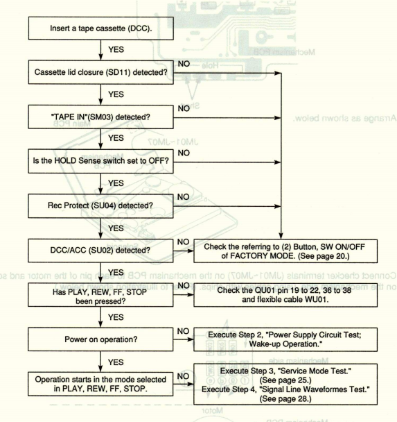
I'm glad that eventually, after I put the DCC-175 together again, it started working again, just as spontaneously as it had stopped working. Weird! I looked through the service manual of the DCC-170 to learn more about the bottom PCB. There's not really much that can keep a DCC-170 or DCC-175 from starting up. I started writing an article about it but then I noticed the service manual already kind of has the information in the form of a troubleshooting flowchart:
![]()
The flowchart doesn't mention that if the lid-closed switch or tape-in switch or hold-switch is not working correctly, you can't power the recorder on. That also means that if the top PCB is not connected to the bottom PCB and the lid PCB, it won't start. Good to know!
The bottom line is: The PCB on the bottom of a DCC-170 or DCC-175 contains the read amplifier, the write amplifier and the motor control circuits. Besides the switches that sense the recorder's status, and let the user operate the recorder, there's nothing that keeps the system from starting. So I guess that's what fixed my problem with the DCC-175 too: all I did was make sure the switches worked, and that made my recorders work again. Yay!
Back to Work!
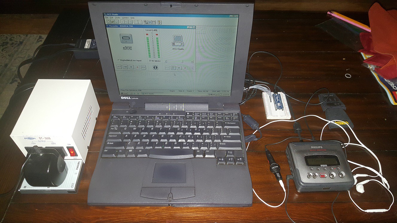
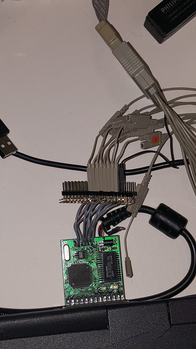
Alright, I guess that means I should get back to the task of writing some software to analyze the traffic that goes back and forth between the computer and the DCC-175, especially over the synchronous serial port. My main problem there is that I don't have much space for a project like that. As you can see in the next picture (which doesn't even have the main computer in it!) it takes up quite a bit of space and it's not a surprise that my wife doesn't want that on the coffee table for anything but a short time. EDIT: I made a solution for that, see the next article.
![]()
I use the original 220V power supply that came with my first DCC-175 because I trust it better than other 110V wallwarts that I bought since I emigrated to the USA. So I need my 110V-220V step-up transformer (left).
I also use my 1999 Dell Latitude CPi-A 300MHz Pentium II laptop (middle) because it's the only thing I have that still runs Windows 98 and has a printer port. It's brittle but it works (for now. Knock on wood!)
The DCC-175 (right) is connected to the laptop via the DCC-Link cable of course but I soldered some wires to it to "break out" the connections between the recorder and the plug.
I'll be writing software for the Propeller, on my usual computer (not shown in the picture).
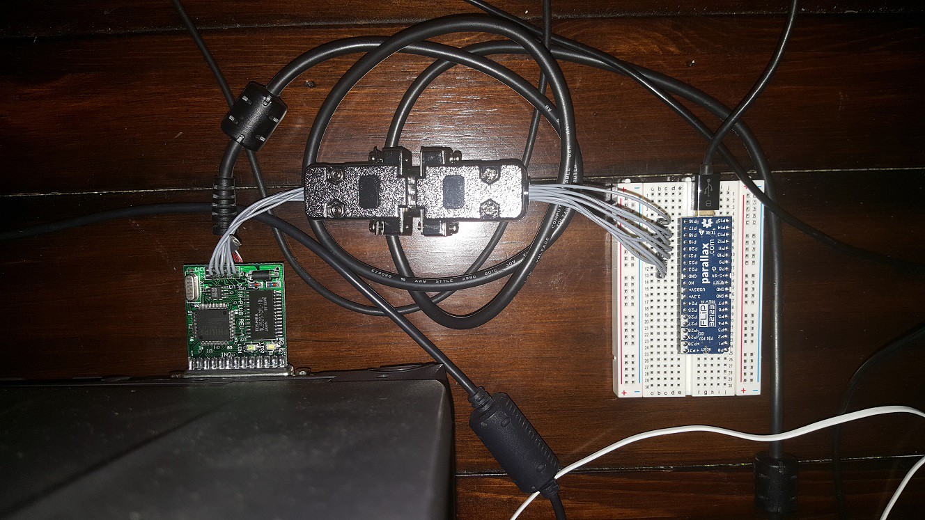
![]()
The photo above is a closer look at the actual test setup which is mostly hidden by the laptop in the previous picture. The DCC-link plug is on the left and the excellent Propeller FLiP is on a breadboard on the right. I found two 9-pin Sub-D connectors in my parts bin that I used to make the breadboard and the DCC-Link plug easy to disconnect. Yes, the Sub-D connectors are only 9 pins; the DCC-Link cable has 10 connections but I don't need the +5V output from the recorder.
I hope the long unshielded cables won't be a problem but I don't know yet. If they do, I'll have to replace the cable, possibly make it shorter too. We'll see. For now, I guess I had better get back to writing some software for the Propeller to analyze the serial traffic.
Post Script
As it turned out, the problem with my first DCC-175 was apparently a defect in the heads. With a working PCB2 from one of the DCC-170s it played only analog tapes but not DCC's, and various other PCB2's didn't solve this. I decided to sacrifice my worst DCC-170 to make my old DCC-175 work again. That DCC-170 had mechanical trouble (severe wow and flutter) that made it impossible to play DCC's and made analog cassettes sound horrible, and the DCC-175 had some problems with lifted PCB traces on PCB2 because I had taken it apart so many times. There were other problems like partially melted plastic parts because I had touched them with a soldering iron. There were also missing screws.
After I combined the best of both, I now have two working DCC-175's and two working DCC-170's and one DCC-170 that I might use for parts and repairs in the future. Less than I hoped, but more than I could wish for when I started on this. Oh well, that's what spare recorders are for.
Unfortunately, I had a small soldering mishap: I wanted to replace a blown fuse from the DCC-175 with a different one, and when I desoldered the old fuse, a tiny ball of solder landed between the pins of a tiny transistor, which released its magic smoke when I powered it up (and blew the fuse again). The recorder still works, but when you turn the power off, it goes into perpetual rewind mode. I'll have to look into that some other day.
-
Analyzing, Please Stand By. Your Call Is Important to Us.
08/19/2018 at 06:54 • 0 commentsAs I mentioned in the previous log, I found out that the microcontroller in the DCC-175 and the custom chip in the DCC-Link cable communicate in blocks of 32 bytes each direction. I've been wanting to set up a Propeller on a breadboard to do some deeper analysis but because it's crunch time at work, I haven't had time.
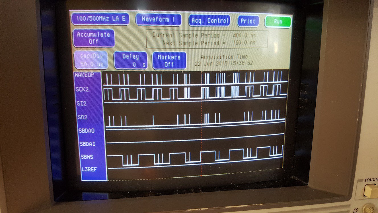
Anyway, I thought it might be a good idea to do a brain dump of some of the details of my findings, along with some pictures of the logic analyzer screen for reference. That way I'll have all the information gathered here once I start programming. I'll also show some timing diagrams from the 3rd generation chipset datasheets.
Warning: This might get a little dry, technical and boring so if you're here to see circuits getting soldered together (or breadboarded) and doing useful stuff, you may want to "sit this one out".
![]() ---------- more ----------
---------- more ----------The Connector Itself
Before I dive into the electronics stuff, let's start with the connector that goes into the DCC-175. To my surprise, it was easy to find: It's the Hirose 3240-10P-C(50). It's still in production, and your favorite large online electronics store probably has them in stock!
![]()
On the original PCA10DC cable assembly, there is a shielded 10-conductor cable of about 1 meter (3 feet) between the two plugs. There's a ferrite bead on the cable near the Hirose plug that goes into the recorder. The cable has to be thin because the Hirose plug only allows a cable outer diameter of up to 5.4mm.
Now for the bad news: I looked at several online stores to find out how much it would cost to buy the same kind of wire and the short answer is: "You don't want to know". 10-conductor shielded wire is not difficult to find, even at the rather tiny specified maximum diameter, and it's also not that expensive per meter or foot, but unfortunately it seems that that exact cable is only available in large quantities. So if I would ever make this into a project that I'll sell, I might end up having to invest something like $1200 (UPDATE: the price has gone up to $1400 as of January 2022) for a roll of 1000 feet (304m) of cable. Ouch!
Once I get further along with the project, I'll have to look into this a little further. Maybe there are other ways to solve the problem. It might be possible to squeeze a slightly thicker cable into the connector (EDIT: Nope! The connector is really only big enough for a 5.4mm outer diameter. The 5.9mm cable that I got, didn't fit and made it impossible to put the connector together). Or maybe I'll be able to find an alternative connector that's a better fit for a thicker cable, or get the right wire in smaller quantities from a different supplier. I don't know yet. At least it's clear that it will be possible to make complete cables (well... without the custom chip) without the need to make any modifications to the recorder.
UPDATE: I found a different cable at a different supplier in January 2022. The cable should be thin enough and it's available in smaller quantities. I ordered some of it and will update this page again when it arrives.
Connections between DCC-175 and the PCB in the Parallel Plug
Inside the parallel port plug, the cable terminates in a connector that goes onto a 2x6 pin right-angle pin header with 2mm pitch on the circuit board. Pins 11 and 12 are not used.
In the Hirose plug on the recorder end, the conductors are connected in order of standard (IEC 60062) electronic color codes, but because there's no pin 0, the colors are "off by one": black (0) is pin 1, brown (1) is pin 2, etc. On the other end (in the parallel port plug), the wires are crossed, and connected as follows:
DCC-Link 2mm
header pinDCC-175 pin Color Signal name Direction
from recorder1 1 Black 5V Out 2 10 White GND Ground 3 9 Grey L3REF Out 4 4 Orange SI2 In 5 5 Yellow SO2 Out 6 3 Red SBDAO Out 7 7 Blue SBDAI In 8 8 Violet SBWS Out 9 6 Green SCK2 Out 10 2 Brown WAKEUP In 5V and GND
The chips in the parallel plug have to get their power from somewhere, and there's no power output on a standard parallel port. So the recorder provides a 5V power supply to the plug.
WAKEUP
The PC pulls WAKEUP down for a short time to turn the recorder's power on.
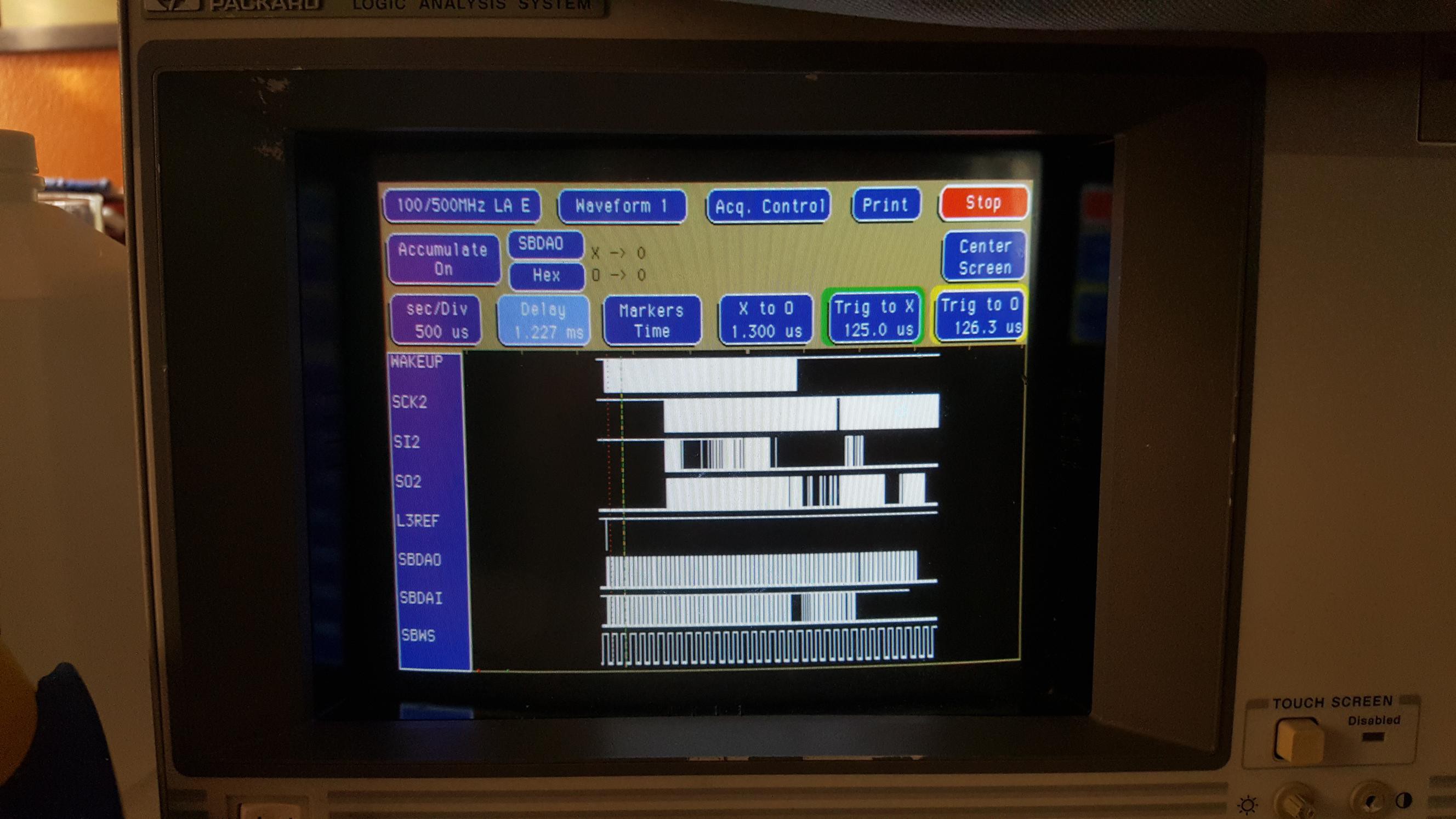
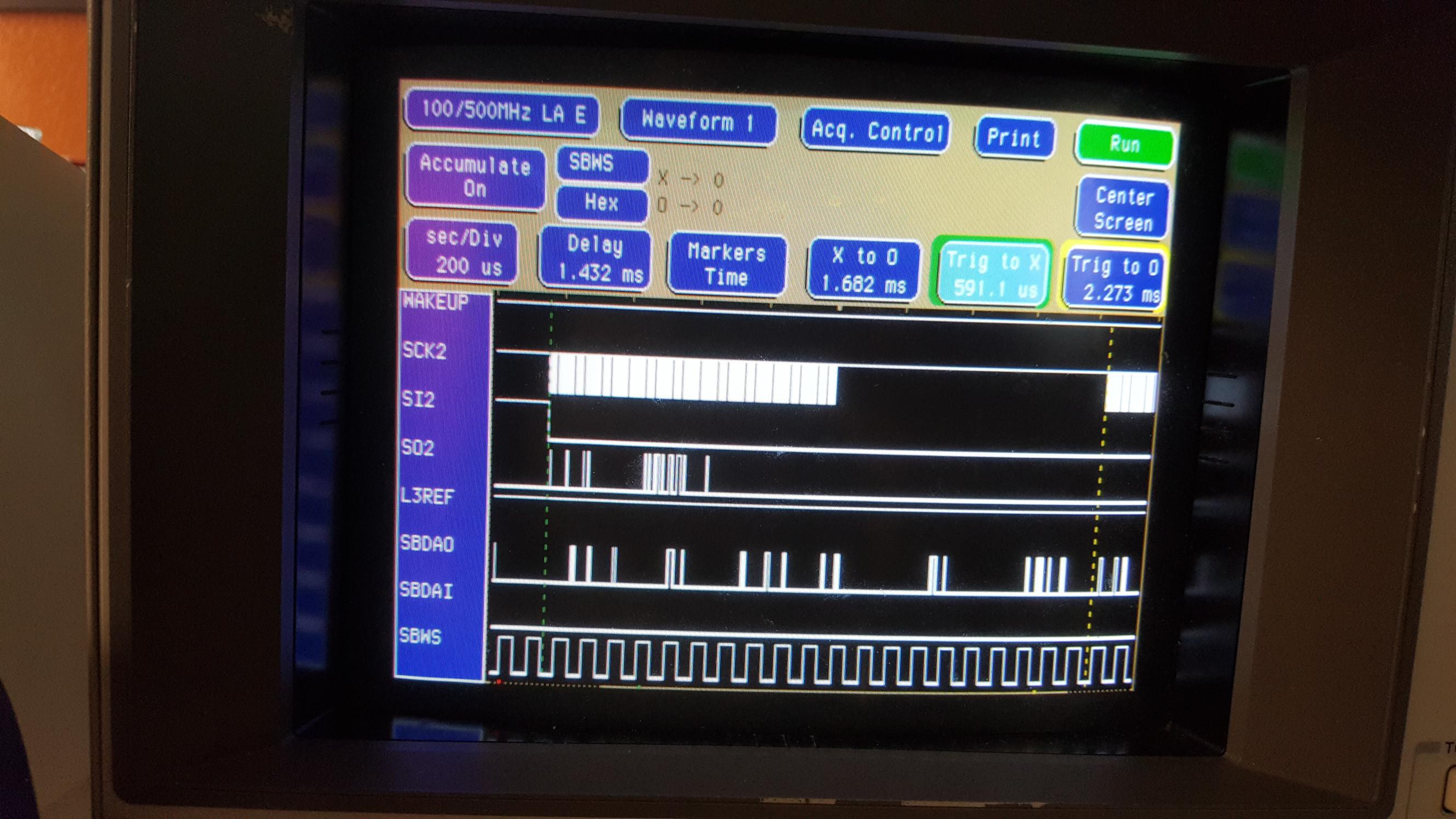
Interestingly, the line is HIGH most of the rest of the time, but not quite always. I observed instances where it was LOW for short times while the recorder was on and working correctly (the picture at the top of this article shows a lot of aggregated pulses on the WAKEUP line). At this time, I don't know if these pulses are:
- false readings
- glitches caused by my setup
- glitches caused by the Philips hardware
- intentional pulses generated by the hardware, e.g. to get the attention of the recorder for some reason.
Either way, the extra pulses that I saw on the WAKEUP line seem to be random and appear to have no influence on the operation of the recorder or the PC. I'll ignore it for now and I'll assume that the extra pulses are unnecessary but harmless.
EDIT: The WAKEUP pin is simply used to turn the recorder on from the PC, and is kept HIGH during PC operation. It appears that the recorder either ignores the input when it's on, or it's an edge-triggered input. Pulling the input HIGH will switch the recorder on, but if the PC doesn't communicate with the recorder, it will turn itself off after the usual timeout, and then turn itself on again immediately.
SBWS, SBDAI and SBDAO
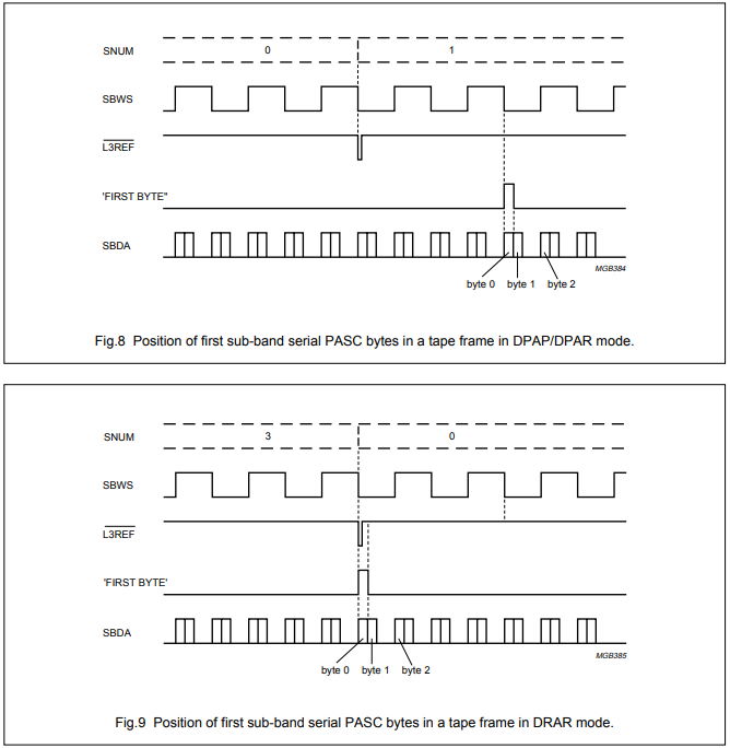
The I2S bus that transfers PASC compressed audio data between recorder and computer, is directly connected to the DRP and SFC. This diagram from the SAA3323 DRP datasheet shows how the PASC data is formatted:
![]()
The SBCL (Sub-Band CLock) is the time-base for the PASC stream. It's generated by the DRP and always runs at 768kHz, which is twice the 384 kilobits per second at which the stream is played and recorded. SBCL is not present on the DCC-Link cable. If it would be, there would probably be too many problems with analog distortion because of the relatively long cable, as well as problems with propagation delay and interference. So instead, the chip on the PC side has to recover the clock. That's pretty easy with a PLL (phase-locked loop) that uses SBWS as input.
SBWS (Sub-Band Word Select) runs at 1/64 the speed of SBCL, just like the Word Select clock on other I2S buses, and the first significant bit starts one SBCL clock period after each transition of SBWS. But unlike other I2S buses, the SBWS state doesn't correspond to the left or right channel, but rather indicates whether the encoded data contains the first 16 bits (SBWS=LOW), or the last 16 bits (SBWS=HIGH) of a 32-bit PASC "slot". Slots are always aligned on a tape frame, and L3REF helps to find the start of a tape frame; see below.
So during each half-period of the SBWS cycle, there are 16 bits of significant data, followed by 16 zero-bits. The PASC stream uses only half of the available bandwidth of the 768kHz bus, making up for the double speed of the bus.
In all DCC recorders, the SBDA line is bidirectional: In playback mode, the PASC datastream on SBDA comes from tape (in third generation recorders: the DRP) and goes to the PASC decoder (in third generation recorders: the SFC), and in recording mode, the data goes the other way.
But the DCC-175 is special, because the computer can also be a source and target for PASC data. To make sure that the PC and the chips inside the recorder can't put data on the subband I2S bus at the same time, the bidirectional SBDA line is connected to the PC using two separate uni-directional lines SBDAI (Sub-band Data Input) and SBDAO (Sub-band Data Output). The microcontroller controls which of the two is enabled (and only one of them can be enabled at a time). That way, if the recorder and the PC ever disagree about which direction the PASC data should flow (e.g. because of a software bug on the PC), no damage can be done.
L3REF
As you might guess from the name (because it starts with L3 instead of SB), the L3REF signal is technically part of the L3 bus, not the PASC I2S bus. Nevertheless, L3REF is used to synchronize the PC with the PASC datastream.
L3 is the protocol that Philips uses in DCC recorders and other equipment to let a microcontroller communicate with a relatively high number of chips. It's similar to an I2C (Inter-IC) bus but it uses multiple chip-select lines to allow the microcontroller to quickly select a slave chip instead of selecting the chip by address, as I2C does.
![]()
The DRP datasheet describes the L3REF signal as follows: "This active LOW output pin indicates the start of a time segment, it goes LOW for 5.2 µs once every 42.66 ms approximately and can be used for generating interrupts for the microcontroller. If a re-synchronization occurs then the time between the occurrences van vary." In other words: this signal can be used to synchronize the microcontroller (and in our case: the PC) with the PASC data stream. And it can be used to trigger the logic analyzer too.
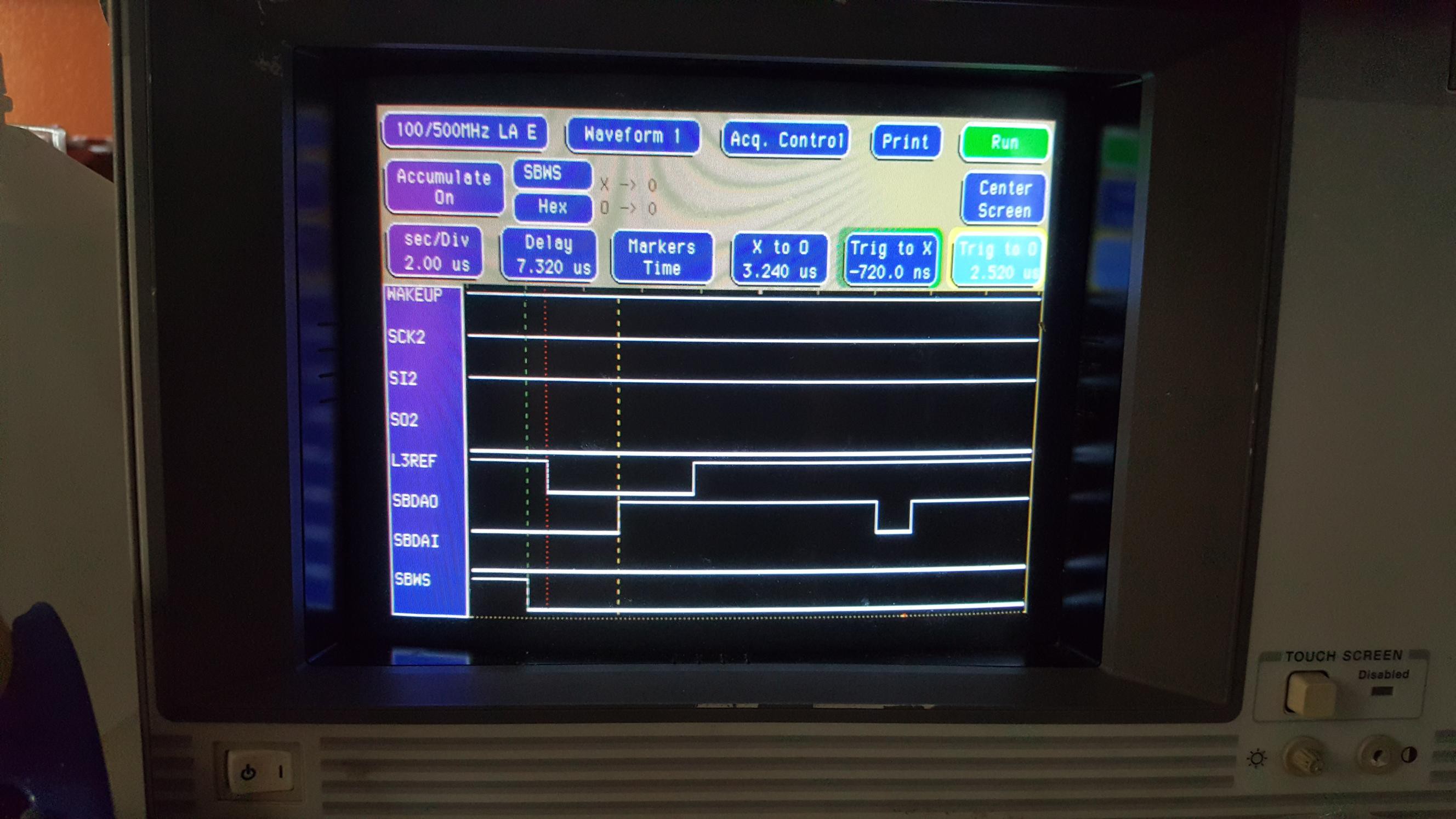
![]()
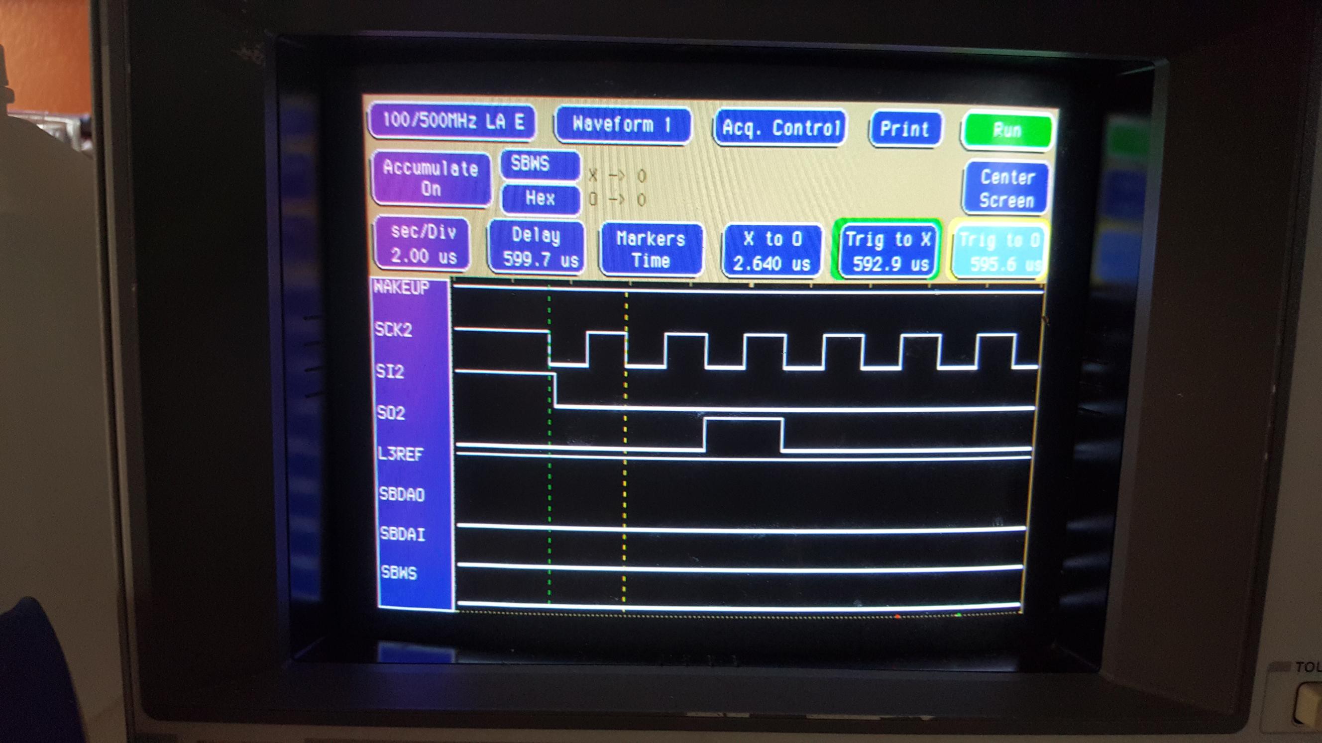
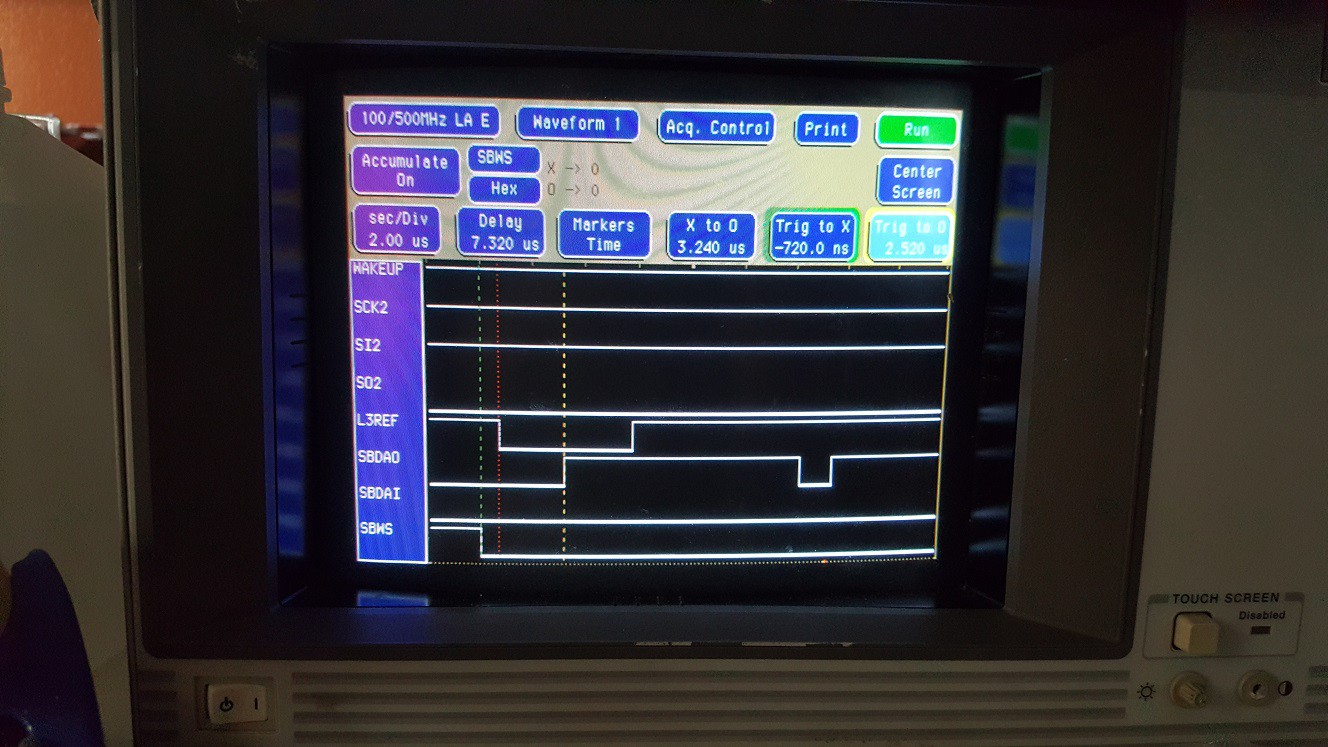
The photo shows the trigger on the point where the L3REF signal goes from HIGH to LOW. The trigger on this logic analyzer is displayed as a red vertical dotted line, you may need to click on the picture to show it in large format and see it. I had the X marker (green) adjusted to the SBWS flank which happens 720ns earlier than the L3REF flank. I don't know yet if this timing is significant (EDIT: it probably isn't).
The O marker (yellow) is on the LOW-to-HIGH transition of SBDAO which happens 2.52 microseconds (one PASC cycle of 1 / 384000 second, minus the 720 nanoseconds, roughly) after L3REF goes low. As you can see, that yellow marker is pretty much in the middle of the L3REF pulse so yes, that pulse is about 5.2 microseconds long as the datasheet says.
The casual mentions of the timing of the L3REF signal are interesting. The actual number of bits in a tape frame (or time segment) is not directly mentioned anywhere in any available datasheet, but those numbers are important because the DRP can only be switched between playback and recording modes at the start of a time segment or tape frame (I don't remember which, at this time).
The PASC data rate is 384 kbps and the I2S bus runs at 768 kHz. It's probably not a coincidence that the specified 5.2 microsecond pulse length is pretty much exactly 4 clocks on the I2S bus, or 2 clocks of the real-time PASC stream: the actual duration of 4 / 768000 second and 2 / 384000 second are within 0.2% of 5.2 microseconds. So for now let's assume that L3REF is low for 4 clocks of the I2S bus, though we won't let anything depend on the actual pulse width.
The quoted "42.66 ms" interval for each time segment, divided by the bit time of 1 / 384000 second is 16381.44. It's very likely that there are actually 16384 bits, because 16384 is a round number in binary and 16384 / 384000 is 42 2/3 milliseconds. That means there are 16384 PASC bits in a tape frame. This is not explicitly mentioned in any public documentation. (EDIT: the DCC System Description document which was donated to the DCC Museum indeed confirms that a Tape Frame contains 8192 bytes or 2048 slots of PASC information, along with 128 bytes of System Information (SYSINFO)).
It surprised me a little that tape frames are not evenly divisible in PASC frames (in other words: PASC frames and tape frames are not guaranteed to be aligned, though each tape frame always starts at the beginning of a PASC slot), but in a way it makes sense: First of all, the PASC decoder could be developed without dependency on the tape format. Secondly, it was possible to use varying sizes of PASC frames, almost without limitation. And thirdly, this left open the possibility that DCC might store audio (or other media) in different formats in the (then) future. And it wasn't that difficult to implement: The Philips engineers just decided to put a slot with value 0xFFFFFFFF at the beginning of every frame, and carefully designed the rest of PASC so that that slot value could never appear anywhere else in a PASC frame.
SI2/SO2/SCK2
This is the bidirectional serial port of the microcontroller in the recorder. The clock (SCK2) is HIGH while idle, and signals are latched upon the LOW-to-HIGH transition of the clock. There are no startbits or stopbits. This makes the serial bus compatible with what's commonly known as SPI mode 3.
![]()
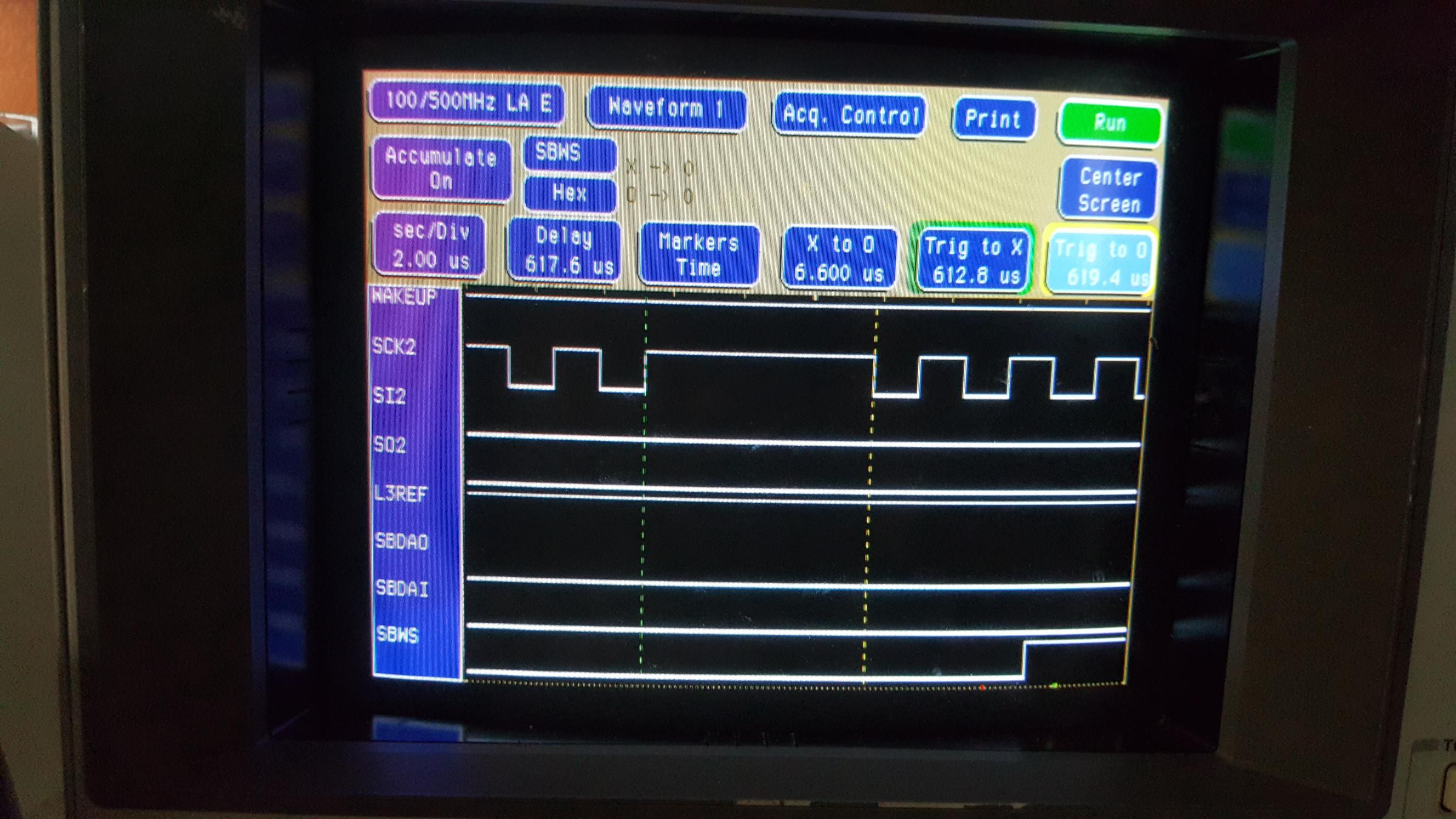
At 592.9 microseconds after the start of the L3REF pulse, the microcontroller starts sending a burst of clock pulses on SCK2. There are always 32 bytes with 8 databits transferred in both directions. When the PC has nothing to send to the recorder, it just keeps its data line (SI2) LOW during the entire time that there are clocks on SCK2.
![]()
The clock pulses are obviously symmetrical and have a period of approximately 2.64 microseconds, as shown above. This corresponds to the somewhat unusual baud rate of 378787.8 bits per second (not too far off from the 384kbps of the PASC stream but that might be a coincidence). I don't know if there's any jitter on this clock (I expect there is none), but any hardware that I will build, will not rely on the measured clock frequency too much, only on the fact that clock pulses at the correct rate are supplied by the recorder.
![]()
The interval between two bytes is shown in the picture above. It looks like the time between bits is about 6.6 microseconds, which is 2.5 bit times. Again, my hardware will not rely on this too much, but it gives me an idea on how to configure my time-outs.
![]()
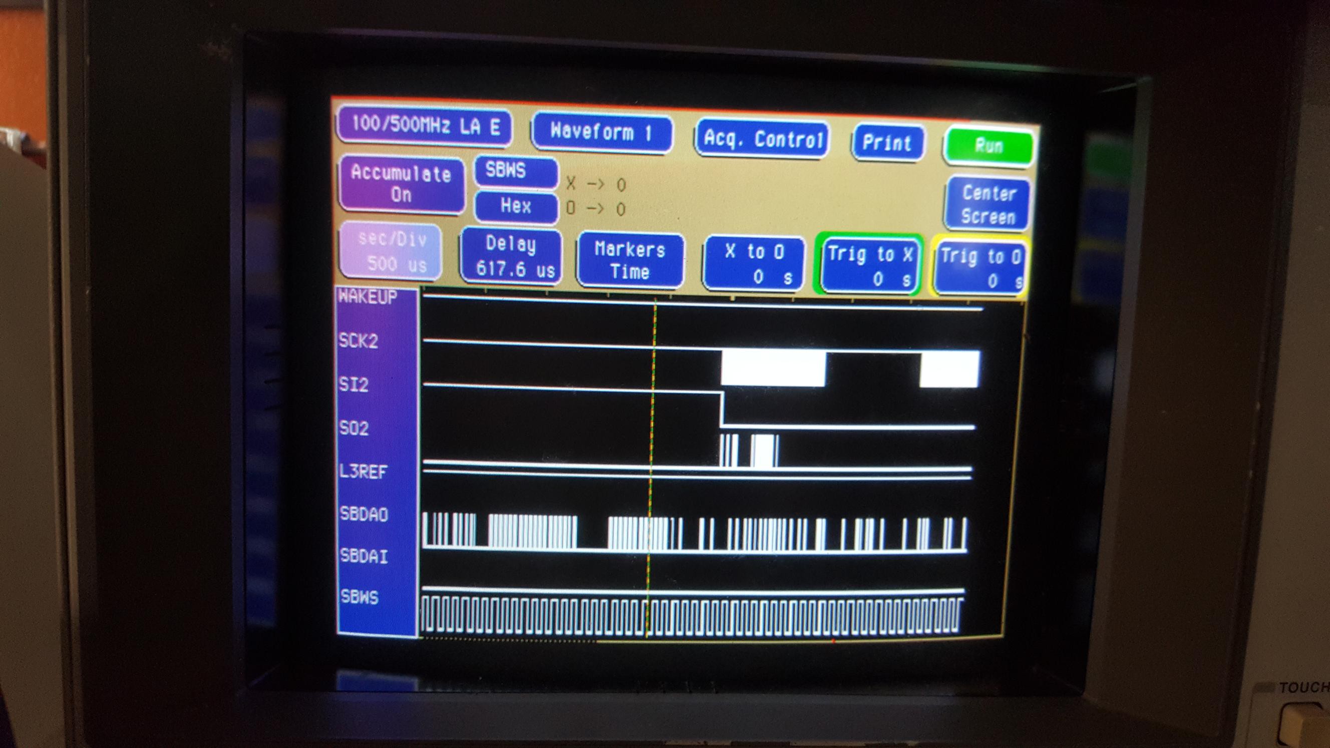
The picture above shows that there are multiple bursts of 32 byte packets, but they don't occur at regular intervals (there are no SI2 clocks on the left side of the picture, i.e. just before the L3REF pulse). The software will have to measure how many packets are transferred between L3REF pulses.
EDIT: I found out later that there are 12 bursts of 32 bytes (384 byes total) of information per tape frame:
- A block of 32 bytes containing 28 bytes of probably recorder status/control and chip info + 4 bytes of AUXINFO
- A block of 32 bytes of remaining AUXINFO data
- A block of 32 bytes of SYSINFO data
All of the above appear 4 times (with different data) during each tape frame. It's not yet clear what the sequence is (i.e. which of the 3 items comes first within a frame) and what data is in the recorder status/control packet.
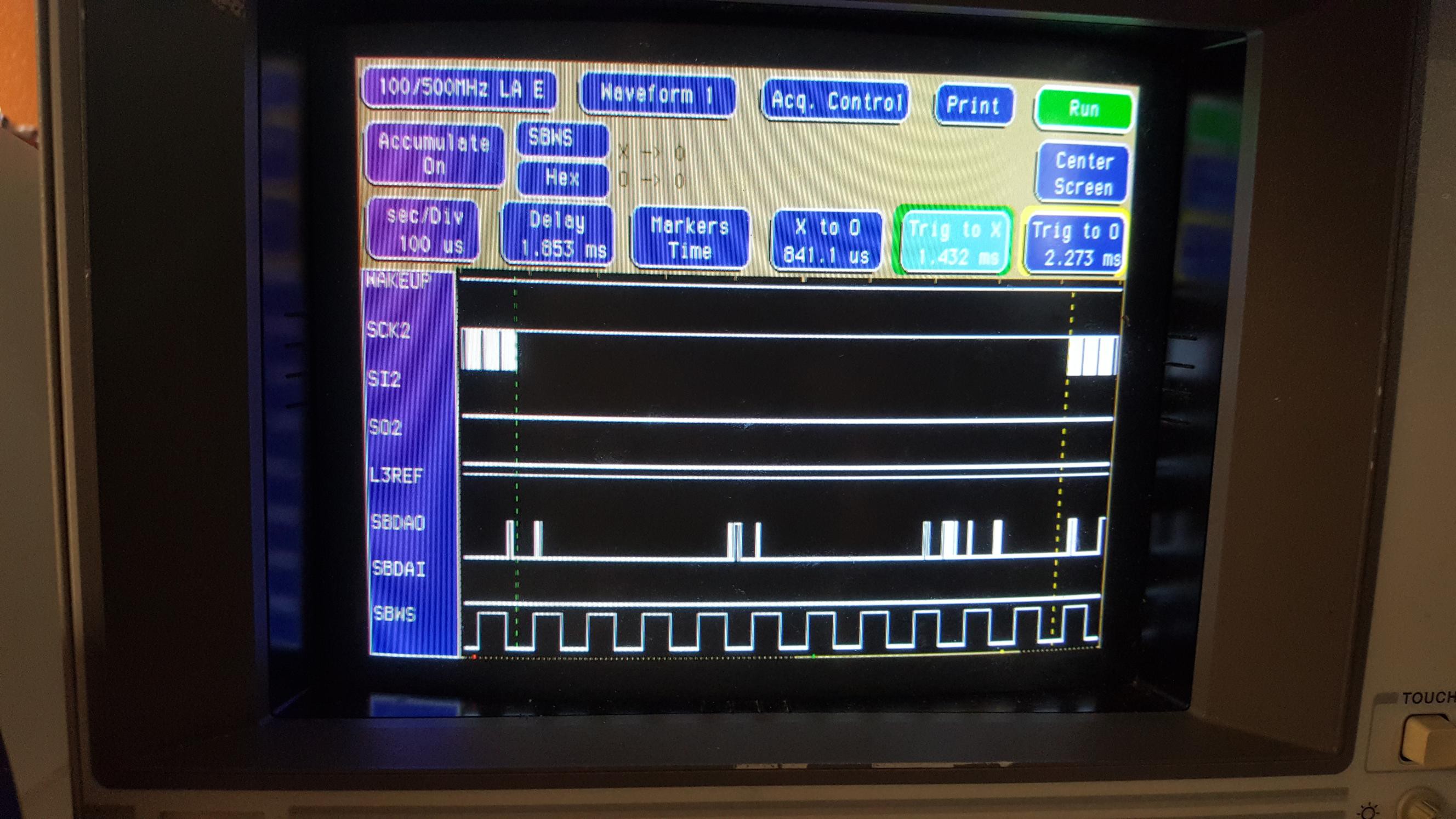
![]()
The picture above shows an entire "packet" on the serial bus. I think this was while the recorder was in STOP mode. A 32 byte packet takes about 841 microseconds, and about 10 SBWS clocks. I wouldn't be surprised if it takes exactly 10 SBWS clocks but I didn't verify this.
![]()
Interestingly, the time interval between two 32-byte packets is also 841 microseconds and 10 SBWS clocks.
![]()
That makes the total maximum time to send or receive and process each 32-byte packet equal to 1.682ms as shown above.
Some More Pictures, Taken in "Accumulation" Mode
You may have noticed in the previous pictures that "Accumulate" was on, but each picture was just a single run. The following pictures are where I let the analyzer run continuously, accumulating all the possible transitions which might help for timing analysis. I don't think timing needs to be accurate down to the microsecond or nanosecond but it might help to know the expected amount of jitter for things such as recovering the I2S clock and adjusting the phase of it to make sure that the PC can record to cassette successfully. Mind you, I didn't actually take pictures while the recorder was in Recording mode, where things might be different because the system might be locked to the incoming audio signal instead of the internal crystals.
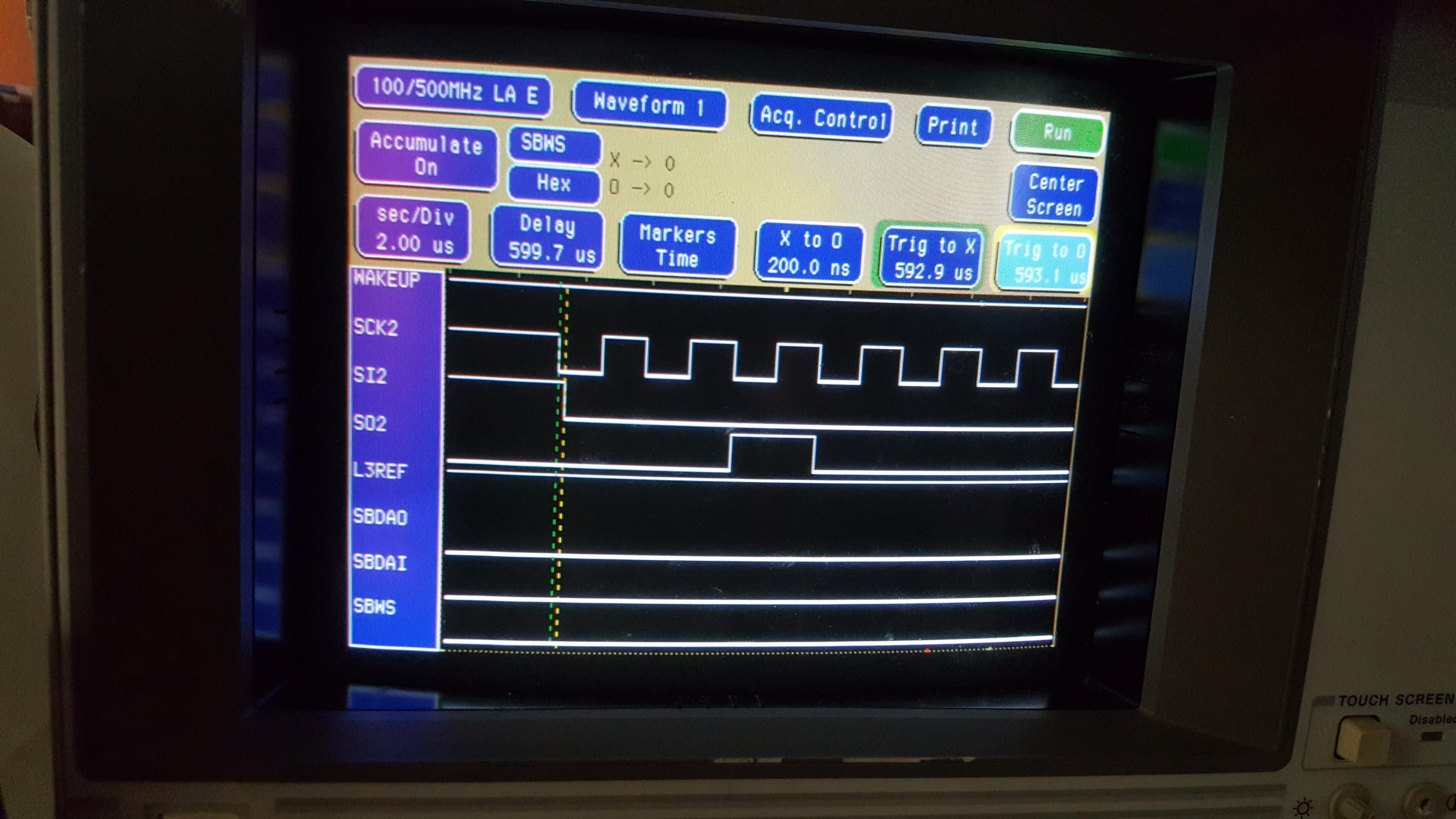
![]()
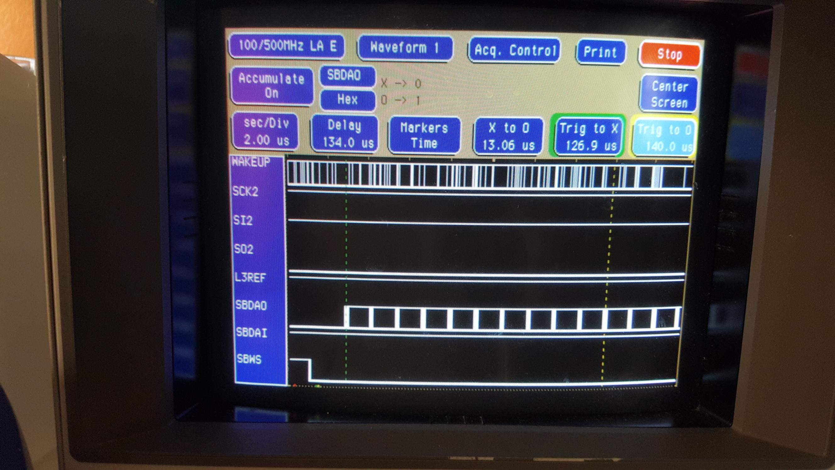
Above: The average time from the start of the L3REF pulse to the first bit on the SBDAO line (recorder to PC) appears to be 125 microseconds.
![]()
Above: 10 bits on the I2S SBDAO bus add up to about 13.06 microseconds so one bit appears to be about 1.306 microseconds. Actually the bit length should be 1.302 microseconds (1/768000); I bet that inaccuracy is caused by me getting sloppy at putting the markers in the center of the transitions.
Conclusion
Unfortunately my analyzer isn't smart enough to interpret the signals on the serial port (as far as I know). It also doesn't have a lot of memory: I think it stores 4K samples per channel (8K when running in half-channel mode). This is where I'm going to need the help of a Propeller or something. It can probably also be done with other microcontrollers if you're reading along and want to try it at home -- by the way did you know the Raspberry Pi has an I2S bus for audio input and output?
I'm going to set up a Propeller on a breadboard (actually I'll probably use a Propeller Flip) and write some software to analyze the serial port and the I2S port. Important questions that I want answered, are:
- How easy is it to recover the I2S bit clock?
- How many 32-byte synchronous serial packets are in an L3REF period? EDIT: Answered: 12 packets of 32 bytes.
- What kinds of packets does the PC send to the recorder? It should be easy to recognize packets that tell the recorder what to do, such as play the tape, reverse, rewind/fast forward, record mode, play file, record file.
- What does the recorder send back? How is TOC information formatted?
- Eventually: how easy is it to play a tape and store it onto e.g. SD card and record it back? Is it possible to clone a prerecorded tape?
-
Now We're Talking!
07/21/2018 at 07:12 • 0 commentsAfter the fiasco that I described in the previous log, where I had connected all the wires in the wrong order, I finally saw some usable data on the Logic Analyzer that made sense. In this log, I'll describe the signals for those who are playing along at home, and maybe haven't read the datasheets and service manuals (or haven't read them as many times as I have).
First of all, let's fix a mistake in the schematic in the DCC-175 service diagram:
![]() ---------- more ----------
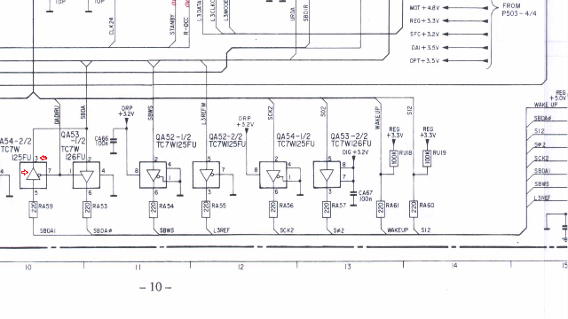
---------- more ----------In the schematic on page 10, near the bottom, there are six tri-state bus buffers TC7W125FU and TC7W126FU to connect the DCC-link cable to the internal electronics. The two buffers that you see on the left of the fragment above, each have one end connected to the PC connector and one end to the I2S bus between the DRP and SFC chips. But in the original schematic, both these buffers are drawn in the same direction (i.e. as if they both send the same data to the computer) which makes no sense of course.
The signals "SBDAI" and "SBDAO" are obviously abbreviations of "Sub-Band Digital Audio In" and "Sub-Band Digital Audio Out", so QA54-2/2 is clearly drawn in the wrong way direction: it's used as an input, not an output. Also, the pin number towards the top of the symbol in the schematic was wrong; it was 2 but it should be 3. The PCB layout on a different page (not shown here) confirms this. I fixed the drawing above and marked the fixups with two red arrows.
About That I2S Bus...
I2S ("Inter-IC Sound", or I-Square-S) is a serial protocol that was developed by Philips Semiconductors (now NXP) as a standard to let components transfer digital audio to each other. Usually these components are chips that are connected via PCB traces or short wires inside a device such as a CD player or DCC recorder.
The bus usually consists of a bit clock signal, a word clock signal, and a data signal. Depending on the application, the transmitter or the receiver may generate the clocks.
![]()
The bit clock determines the speed of the bits, and the most significant bit of the data is usually transmitted first (the data is big-endian). When PCM data is transferred, the data is encoded as a 2's complement signed value of up to 32 bits. The word clock is used to switch between the left and right channel: Low is left, High is right. The word clock runs at 1/32 the speed of the bit clock, and interestingly it switches between high and low one bit-clock-time before the first bit of the word is transmitted and received. This may not sound like an easy way to do things, but it is. It makes it much easier to deal with differences in propagation time.
I2S is used a lot in DCC recorders. And not only for 16 bit or 18 bit PCM audio. The SFC and DRP exchange PASC data via an I2S bus too. The bit clock for the PASC connection always runs at 768kHz; the PASC signal only uses half of the bandwidth of the I2S bus: only the first 16 bits of each 32 bit word is used (this is documented in the SFC datasheet). The word clock for the PASC I2S bus is used to indicate whether bytes 0 and 1, or bytes 2 and 3 of a longword are transported. An extra line L3REF is used to indicate the start of a PASC packet.
The L3REF, WS, and SD signals of the PASC I2S bus are available on the DCC-link connector of the DCC-175. The L3REF and WS lines are always outputs, but the SD line is split up into SBDAO and SBDAI depending on whether the recorder expects PASC data from the computer (for playback or recording from file) or not. But there is no bit clock. What gives?
Since the PASC data rate is always 768kHz and since it's always generated by a crystal (even when the recorder is recovering data from tape!), it's not essential to put the bit clock on the cable. The clock can be easily recovered by using the WS line to control a PLL. Or even easier: the PC side of the cable can simply use its own clock and counter that uses its own clock that's "close enough" and use WS to reset itself every 64 bit times (the WS clock runs at 1/64th of the frequency of the bit clock). The timing and format of the sub-band I2S bus is pretty well documented in the datasheets.
We're going to ignore the I2S bus for most of this project because there's basically nothing else to reverse-engineer about it. But let me mention one more thing that might be important later on: Tape frames and PASC frames are not aligned. PASC frames can even have various sizes depending on the sample frequency. So there's no expectation that whenever there's an L3REF pulse, there's a beginning of a PASC frame. There isn't. The PASC decoder doesn't know (or need to know) how the data is framed on tape; it uses the sync pattern FF FF FF FF to find the beginning of a PASC frame.
![]()
Analyzing the Synchronous Serial Port
There is almost no information about what the Philips/Marantz engineers put into the uPD78058 microcontroller that the DCC-175 uses to control all the DCC chips. But the datasheet of the microcontroller does have some information about how I/O pins P20, P21 and P22 can be configured for synchronous serial I/O, as they did in the DCC-175.
I expected that the serial communication would be sort of like a regular serial port with a clock line. I thought the serial clock would probably be running all the time, and the PC as well as the recorder would use the clock to put data on the input and output, and it would be up to me to interpret what the commands were, and how data such as the Table of Contents would be formatted. But when I connected the DCC-link to the analyzer, I noticed that SCK2 (the serial clock) was hardly ever running. For example in the picture above, SCK2 is not active. So how can the computer send commands and receive updates from the recorder?
The answer was an interesting surprise.
![]()
The microcontroller in the recorder and the PC communicate by exchanging fixed length packets of 32 bytes: each little block on the SCK2 time line in the picture above is 8 clock pulses and there are 32 of them. When I kept the analyzer running, it looked like the data coming out of the recorder on SO2 was pretty much mostly the same for each packet (the recorder was in STOP mode).
This might not sound like a big deal but this actually answers a lot of questions about timing, possible ordering of commands and responses, timing, synchronization etc.
Clearly, the recorder determines when it needs to do an update; it doesn't even matter how often this happens. The chip in the DCC-link cable can easily recognize the start of a packet by measuring the time between clock pulses. During an update sequence, the recorder microcontroller sends a status update to the PC, and at the same time receives a status update from the PC. From a software point of view, this makes things really easy: When some part of the software (either in the PC or in the recorder) needs to make a change, it can update the 32 bytes in memory that are transferred during the status update. The actual status update can be a timer interrupt handler on the microcontroller and I wouldn't be surprised if the chip in the DCC-link cable completely takes care of exchanging the information; the PC software probably updates its information at its own pace, with help from the printer port and 4-bit, ECP and EPP protocols.
This is great news, because it gives me a clear direction for what the next step should be. I'm going to use a Propeller on a breadboard and use it to connect to the DCC-link, while it's also connected to the PC and the DCC-175. Then I'll write some software that listens for the 32-byte packets and records the data that goes in both directions. And the nice thing of a Propeller is that I can probably record the PASC data at the same time, and either store all the data on an SD card or simply stream it to another PC via high-speed RS-232-TTL. Then I'm going to see if I can make heads or tails of the serial data.
-
Log All the Fails!
07/20/2018 at 06:01 • 0 commentsI finally started to do something that I've been wanting to do for over 20 years: use a logic analyzer to figure out how the DCC-175 communicates with the PC. It didn't go so well but I fixed my mistakes. If you want, you can skip this log to go to the next log which will have some juicy interesting stuff (arguably?). If you want to find out how I made a stupid wrong assumption that threw me off for a few days, keep reading.
![]() ---------- more ----------
---------- more ----------I had attached the pins of the DCC-link cable to the logic analyzer based on the schematic in the DCC-175 service manual. The other end of the cable was connected to my 1999 Dell Inspiron laptop running Windows 98. But instead of the signals I was expecting to see, I got the mess that you can see above. Obviously, that picture makes no sense at all. Lots of spikes, and none of the wave forms look anything like I would expect. It looked like there was a lot of interference, possibly a problem with grounding.
Grab a Hold of This
So I back-tracked what I did:
First of all, I had tried to connect the grabbers of the logic analyzer to the right-angle connector that's in the DCC-link plug and connects it to the cable to/from the recorder. Right angle connectors usually have plenty of blank copper and space to clamp the grabbers of the logic analyzer, right?
Well... No. My HP 16500C logic analyzer from eBay is at least 20 years old and most of the grabbers left their best days behind them a long time ago. The header on the DCC-link circuit board uses 2mm spacing (not 2.54mm) and the grabbers are just a little too thick, and they don't grab that well anymore either. And though it looks okay in the picture below, doing my project this way was going to be pretty frustrating with grabbers flying off in all directions all the time.
![]()
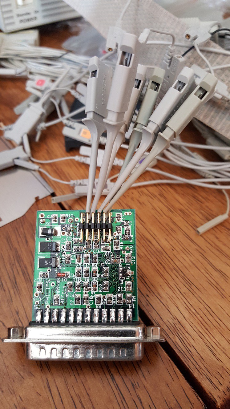
So I had decided I needed something that would be a lot more sturdy. Maybe I could just make something that I could plug straight into the pod of the logic analyzer?
I soldered some wires to a straight male header from my modest parts bin. I kept the wires short to minimize the chance of interference and/or skewed timing readings.
![]()
But the pins kept getting pushed or pulled out of the header and then they were a pain to put back.
Let's try again, this time with a right-angle header so the force on the pins is mostly sideways instead of longitudinal, so hopefully that way they won't come out of the pod. That seemed to solve the mechanical issue, but I still got a lot of that interference and even if I ignored the interference, the signals made no sense. I gave up and didn't have time for the project for a few days.
When I came back, I decided to go back to the drawing board.
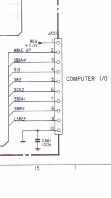
![]()
The picture above is the part of the schematic of the DCC-175 that shows the computer connector. But I knew the cable is shielded so the shielding is not in the schematic drawing. Maybe I needed to use that as reference ground? But that didn't make sense, since the DCC-link works fine without the shielding attached to anything.
I started doing some measuring with a multimeter, and the first reading was immediately way off: instead of 5V between pin 1 and 10 on the DCC-link circuit board I measured something that wasn't even close. But that didn't make sense: The LED lit up while the circuit wasn't even connected to anything except the recorder. So it was getting 5V just fine, nothing was broken.
I've had the computer side of the plug open many times since 1995 and I don't even have the cover on it nowadays because there's a coating on it that's changed composition and made it all sticky and yuck. But I never had the recorder side of the cable open until now. I opened it to see if something was loose (and for giggles). Was the ground pin connected to the shield of the cable but not to pin 10, or something? Nope. All the pins of the connector were connected to the cable. The cable is nicely color-coded by the way, and the conductors in the cable was attached in an order that made total sense (if you know the values of the color codes on resistors): black=pin 1, brown=pin 2, red=3, orange=4, yellow=5, green=6, blue=7, violet=8, grey=9 and white=10.
Wait a minute.
Once I saw how orderly the plug on the DCC-175 side was connected, I remembered that I hadn't noticed that kind of order and regularity on plug at the other end.
I had completely overlooked the possibility that the pins on the PC end of the cable might not be connected in the same order as the other end. I guess I've spent too much time in a world where connectors are mostly connected by ribbon cables where a twist in the wire is always obvious. The engineers who designed the DCC-link plug weren't bound to the order in which the signals were connected to the plug, because it was easy to switch conductors of the multi-conductor wire at assembly time.
That explained a lot: Not only was I using one of the signals as ground reference, I also had pretty much all my wires crossed.
DCC-175
pin numberWire Color DCC-link
Pin NumberSignal Name 1 black 1 5V 2 brown 10 WAKEUP 3 red 6 SBDAO 4 orange 4 SI2 5 yellow 5 SO2 6 green 9 SCK2 7 blue 7 SBDAI 8 violet 8 SBWS 9 grey 3 L3REF 10 white 2 GND Order Please!
After I corrected my mistake, the logic analyzer was still showing crappy signals but they made a lot more sense now.
When I read through the manual of the analyzer, I found out there's a small RC filter in the leads between the pod header and the grabbers. Alright, fine. So I can't plug my jig straight into the pod, but I can plug in the grabber header and connect the end to each of my connector without the grabbers. This turned out to be a nice way to keep everything attached while I would play around with the logic analyzer.
![]()
Note, nothing is connected to pin 1 (the 5V power supply of the DCC-link from the DCC-175). I don't need to analyze that. So the black ground lead is now correctly on pin 2, and I made sure the rest of signals were correctly configured in the logic analyzer.
Now all signals started showing up rock-solid on the analyzer, and they started making sense too!
![]()
All of the signals are now very clear; there's a glitch on the WAKEUP trace in this picture but it's not very important anyway; it obviously just signals to the recorder that a PC is attached and wants to control it. (EDIT: I found out a way to fix the WAKEUP signal later).
I had the analyzer set up so that it triggered on the L3REF signal which is a short pulse to indicate the start of a tape frame, according to the SAA3323 datasheet. The data that's coming out of the I2S bus (SBDAO and SBWS) is what's expected, and the format of the serial data was somewhat of a pleasant surprise; more about this in the next log.
Now that the setup is in a working state, I can get serious with the reverse-engineering project. In the next log, I'll show what I discovered so far and how I'm going to proceed.
-
Introduction to the DCC-175
07/18/2018 at 03:45 • 0 commentsIt shouldn't surprise anyone that a DCC recorder is significantly more complicated than a regular cassette deck.
This article gives an overview of the general architecture of a DCC recorder, and the DCC-175 in particular.
![]() ---------- more ----------
---------- more ----------The diagram above is the block diagram for a typical "third generation" DCC system (I may go into the generations of DCC later, in a different article). The parts that are marked in grey are only needed for recording. I copied the diagram from the SAA3323 / SAA2023 datasheet. The SAA3323 and SAA2023 Drive Processors (DRP) are functionally identical but the power supply voltage is different.
DCC Recording
To record audio to tape, an A/D converter or an S/PDIF digital audio input provides an I2S stream that represents the incoming audio. This signal is basically a synchronous serial version of the PCM data on the input. It can be monitored on the outputs of the D/A converter and S/PDIF outputs, but it also goes to the Stereo Filter Codec (SFC).
The SFC filters the incoming signal into 32 frequency bands. For each band it calculates how loud the frequency band is and what the phase is, using Fourier transformation. The information that's generated here can theoretically be used to synthesize a signal that's identical to the source signal.
The "magic" of PASC lossy compression (which is the predecessor of MPEG-1 layer 1) happens in the Adaptive Allocation and Scaling chip (ADAS3). This chip gets the full load of information from the SFC, again, via an I2S bus.
The ADAS3 chip uses tables and calculations to determine which frequencies are under the threshold of human hearing, and/or are masked by other frequencies. This is called a psycho-acoustic model. Based on this, it determines which frequency bands are more important and which frequencies matter less. The most important frequencies are encoded with more accuracy than the less important frequencies, and some frequencies may not get any bandwidth allocated at all. The result is a 384kbps PASC data stream over another I2S bus, which is basically an MPEG-1 Layer 1 stream. The ADAS3 sends that stream to the SFC which forwards the data to the DRP.
The DRP generates a tape data stream that's divided into blocks and frames. Each tape frame contains 8192 bytes of PASC data, and 128 bytes of System Information (SYSINFO) data; the rest is used by error detection and error correction data. The data is encoded using the 8-to-10 encoding algorithm to avoid writing more than a few consecutive 0-bits or 1-bits to the tape. SYSINFO data includes copyright information and recording format information (such as whether the cassette was user-recorded or prerecorded), and also contains text information for prerecorded tapes.
The result is a raw data stream that gets scattered to the 8 digital tracks on the tape. The scattering follows a fixed pattern so that if a tape dropout occurs, it's more likely that the error correction codes will be able to recover the missing data. The data rate per head is 96kbps; a total of 768kbps for all 8 data tacks. That's twice as many bits per second as the PASC stream!
The Write Amplifier (WRAMP) records the raw stream to tape. The encoding of the bits at this point is very simple: the write amplifier either generates a positive or negative pulse in a small coil inside the head assembly (one coil for each track). and the pulse gets gets stored on tape as magnetization in one of two directions. That means that it's not necessary to erase the tape (neutralize the direction of magnetization): in the end, the recorded tape is entirely magnetized; some parts in one direction, some in opposite direction.
The auxiliary ninth track of DCC is also written by the WRAMP and the heads, but the main data tracks and the auxiliary track can be switched from recording to playback and vice versa separately. The aux track contains things like markers that indicate the start of a track. The data rate of the aux track is much lower than the data tracks (only 12kbps instead of 96kbps) so that it can be read even while the tape is going past the head at high speed, while the DCC player is searching for a track. The aux track can also be erased (unlike the other tracks); the head amplifier accomplishes this by sending positive and negative pulses to the head at double speed, generating a 192kHz signal that neutralizes the tape magnetization.
While recording, the capstan motor runs at a fixed speed of 4.76cm/s (1 7/8ips).
DCC Playback
In playback mode, the Read Amplifier (RDAMP) sends a small electric current through the Magneto-Resistive (MR) head to generate a magnetic bias that makes it possible to read the signals from the tape. The current is not strong enough to re-magnetize the tape. The magnetization of the particles on the tape cause the current in the heads to vary enough to pick up the encoded bits. Remember, both values 0 and 1 are encoded as magnetization, only in opposite direction; tape with neutral magnetization has no value.
The RDAMP samples the signals about 3.2 times faster than the original write speed, and multiplexes the amplified analog samples into a signal called RDMUX. This is sent to the DRP.
The DRP equalizes the samples and digitizes them. It figures out where each new bit on the tape begins, and then applies the 10-to-8 demodulation. Now the data goes through an error detection and correction matrix. The result is the original 384kbps stream that was previously generated by the SFC and the ADAS3 chip during recording.
The DRP also detects if the frames of data are coming in too fast or too slow, and generates a PWM signal for the capstan motor. There is buffering in the DRP to help compensate for speed variations in the mechanism.
The PASC stream leaves the DRP as yet another I2S signal, to the SFC. The SFC is in decode mode, so the ADAS3 isn't needed and is on standby. To decode the signal from PASC to PCM, all the SFC has to do is to synthesize the frequencies of each band with the parameters from the PASC stream, and mix them together digitally into a PCM stream. That PCM stream goes to the I2S bus that's shared with the D/A converter and S/PDIF encoder.
Analog Playback
When playing analog tapes, the recorder simply uses two of the DCC heads to pick up the analog signal. The RDAMP reads these and amplifies them as needed. They are processed through a Dolby noise reduction chip (not shown in the drawing above) and, for portable recorders, a chip (also not in the drawing) that can amplify the signal to headphone and analog output signals. The headphone output has a volume control and an optional bass boost filter. The analog output is also connected to the A/D converter so that the S/PDIF encoder can generate a digital signal even when there's an analog cassette in the machine.
Communication between the Chips
All of the chips mentioned above are under control of a microcontroller. The L3 bus consists of a clock pin, a signal pin and a direction pin. The microcontroller sends synchronous serial bytes over the clock and data lines to give commands to the chips. Each chip has their own address. To let the chips answer, the microcontroller holds the chip active while it sends clock signals. The chip's data pin is now an output and the microcontroller's data pin is an input.
When playing a DCC cassette, the DRP provides the microcontroller with a copy of the SYSINFO data that's part of the main data stream, and the AUXINFO data which is what's on the 9th track, The microcontroller can send the text data out on the User Data subchannel of the S/PDIF output, to be processed by an ITTS (Interactive Text Transmitting Service) decoder. There were never any DCC recorders that could decode the ITTS information but the DCC museum not only has a recorder with a (non-working) built-in ITTS decoder modification, but also an external decoder (of which only a few prototypes were made), The external decoder only works with the first and second generation recorders and was used in mastering facilities to check if the ITTS information on prerecorded tapes was correctly formatted. We can only speculate as to why Philips never made it possible for consumers to decode the ITTS information on prerecorded cassettes.
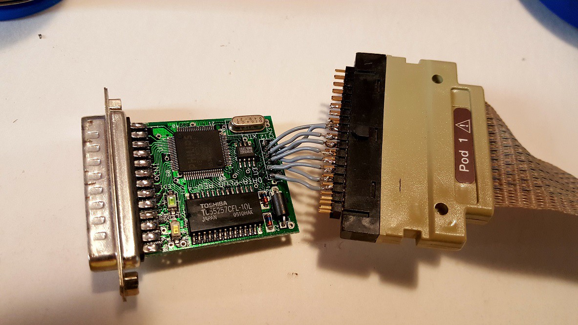
DCC-175 - The Precious
The DCC-175 is unique among DCC recorders, because it features a connector to which a computer can be attached. Philips sold the DCC-175 in combination with the cable (as "PCA11DC") but also sold the cable separately (as "PCA10DC"). The cable is also referred to as PC-Link or DCC-Link.
Not many cables were made; there was a shortage of them even before the DCC format was discontinued. The DCC-175 was only available in the Netherlands and the cable was pretty much impossible to find. And it wasn't possible to change a DCC-170 into a DCC-175 or replicate the cable: there was a custom chip in it to connect it to the parallel port of a Windows PC, and the 16-bit software used direct access to the parallel I/O chip to communicate with the custom chip, so it only works with Windows 98 and earlier.
But the service manual of the DCC-175 and the datasheets of the DRP and the microcontroller make it pretty clear that the cable is simply a connection to a bidirectional synchronous serial port on the microcontroller, and a bidirectional connection to the I2S bus between the SFC and the DRP.
On the PC, Windows sees the plug as a plug-and-play device for which there is no driver. The documentation says that the printer port can be set to standard mode (not recommended), EPP or ECP mode. Someone who started on reverse-engineering the software and the plug in the 1990s (but never finished), found out that the custom chip may have been produced in cooperation with (or by) Shuttle Technologies, which is/was a company that produced parallel port interfaces for SCSI tape drives (which totally makes sense).
The microcontroller on the DCC-175 that controls the DCC chips, accepts commands from the control panel of the recorder but it also listens for commands from the PC. The PC can tell the recorder to do things such as:
- Play a DCC tape and operate the transport (fast forward, rewind, go to next track, etc.) While this happens, the I2S output on the cable carries the same signal as what the DRP sends to the SFC.
- Monitor audio from an input (digital optical, digital coax, analog line or analog mic) and encode it to PASC. When this happens, the I2S output on the cable carries the same signal as what the SFC sends to the DRP.
- Record audio from the PC to tape: The SFC is put in a mode where it doesn't attempt to send data to the DRP but still generates the necessary clock signals.
- Switch the auxiliary track from recording to playback and vice versa, catch any markers that are detected during searching and playback, and record AUXINFO to tape from the PC.
The microcontroller stays in control of the DRP. The way that the PC and microcontroller communicate, is part of what I hope to find out in this project.
Future Plans
Obviously the DCC-175 is a unique device and it's very rare. Not quite as rare as the DCC-Link Cable but still. The initial plan is to reverse-engineer how the microcontroller and the custom chip communicate with each other. It's already clear that with current technology, it's probably easy to implement the same communication protocol on a Parallax Propeller. The Propeller can then be used to e.g copy all the audio from a tape to an SD card in PASC format, or even to send the PASC data over a serial connection (384kbps is not that hard to do in 2018).
Depending on the kind of reactions I will get to this project, and on how smooth things are going to go, I might continue from there in one of the following ways:
- Create firmware for the Propeller to do things like create a song library on an SD card and automatically create compilation tapes, and/or
- Write software for Windows to communicate with the Propeller through the serial connection and do useful stuff(TM) such as create compilation tapes and edit PASC audio waves, and/or
- Reverse-engineer the original software that came with the PC-Link cable, patch it and recompile it so that it works on 32 bit and 64 bit Windows, and/or
- Reverse-engineer the original sfotware and create an actual replica cable that works with the unmodified software, and/or
- Reverse-engineer other recorders to give them capabilities similar to the DCC-175 with DCC-link cable.