Close
0%
0%

WiFi ePaper

WiFi connected, solar powered, ePaper

Similar projects worth following
A solar powered ePaper with an ESP32 to update the display over WiFi, and magnets to stick it e.g. on a fridge, and a cloud app with which you can write and draw on it.

Idea

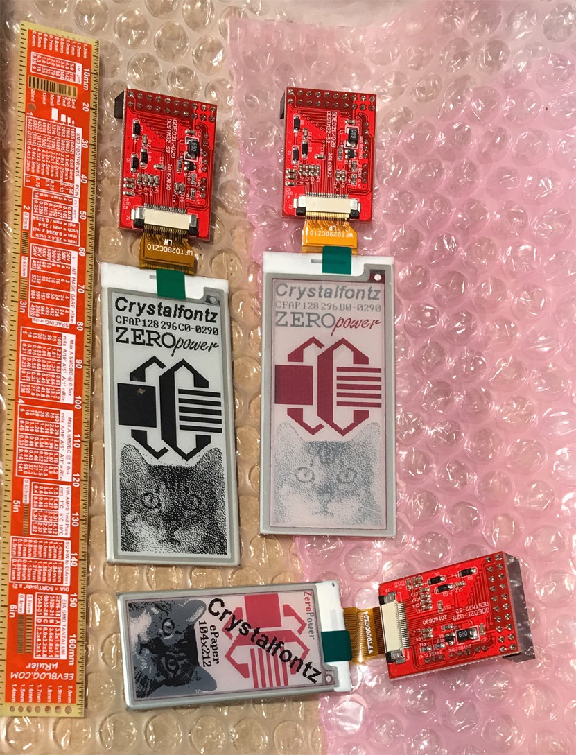
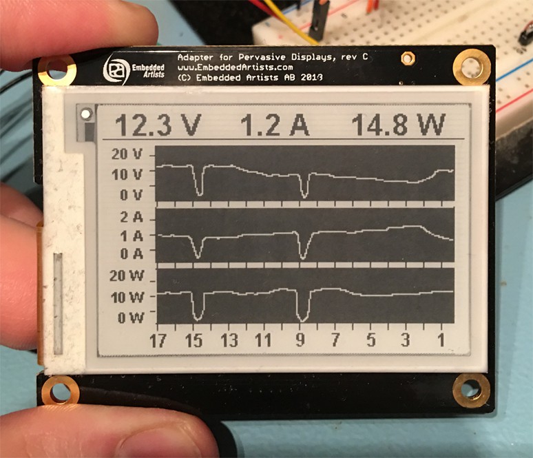
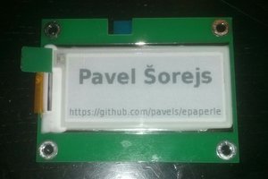
A while ago I bought an ePaper and displayed some images with my RasperryPi on it. See here for a video of it, with a link to full source code etc. in the description:

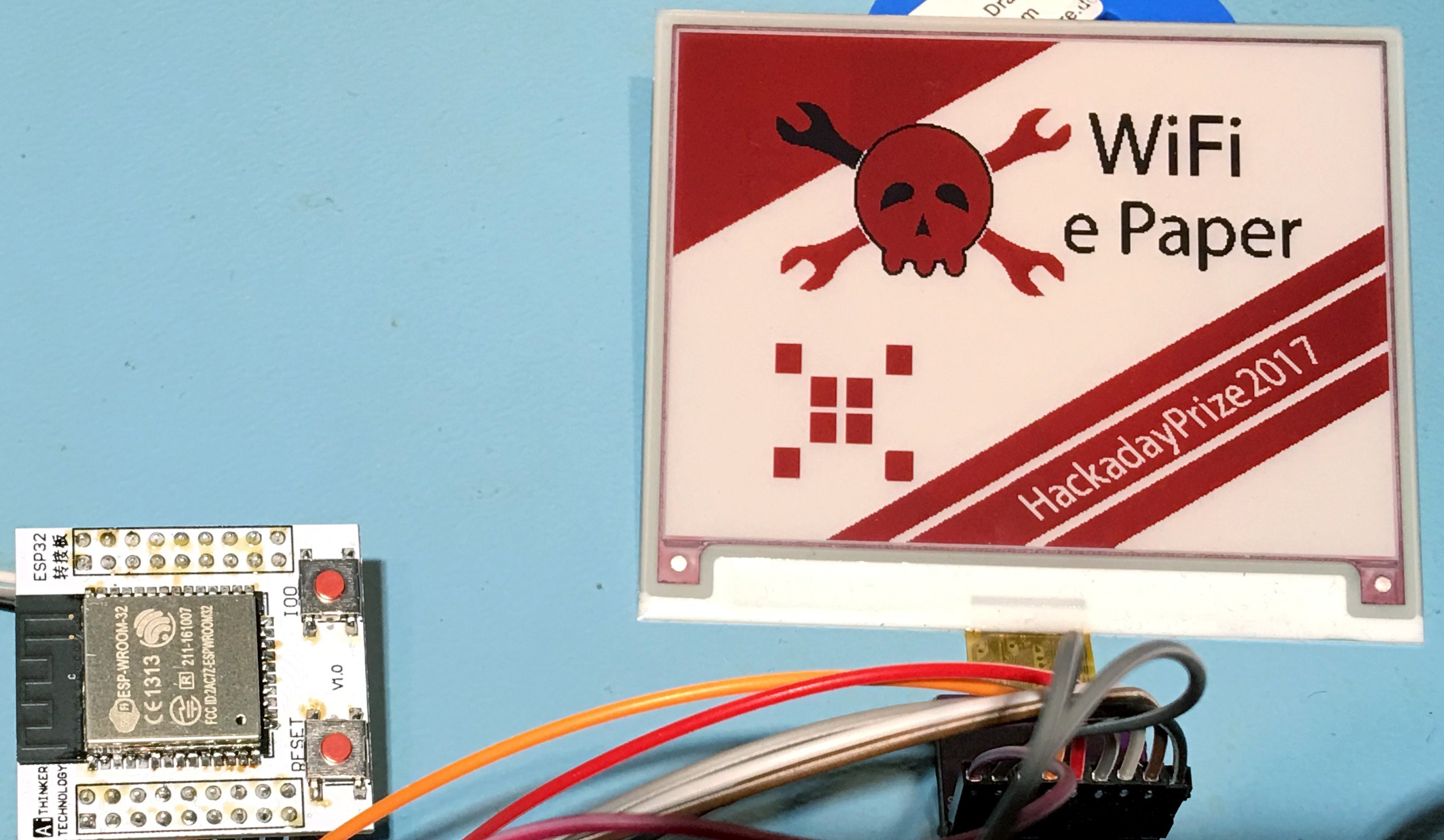
The amazing thing about ePapers is that the image lasts without power forever (I tested it for months), and the contrast is very good. The idea is to build a small device with ePaper and solar cells, and then you can write or draw on the it with your smartphone, or even remotely from anywhere over the internet to show a message. The case will have magnets on the back to stick it on a fridge or other metal objects. It will use an ESP32, which polls a server once per hour to get a new image to display.

This is the electronic version of sticky notes. But the ability to update it over the internet opens up many novel applications. For example install it on the fridge of your grandma, who might not be very proficient in using modern internet connected devices. Then you can send her birthday wishes, or remind her of schedules. And the buttons could be used as a feedback channel, like confirming a date. Or when installed at a public place, it can act as a bulletin board. Or it can be used for a modern form of internet connected graffiti or other art projects. The possibilities are infinite.

Implementation details

Each display has a unique ID (I think I can use the MAC for this, to avoid manual configuring it) and the server can be configured in the ESP32 to which the display connects. On the server side, multiple displays can be registered with a name, and updated, individually, or multiple with the same content. Device architecture and example or one device and one server:

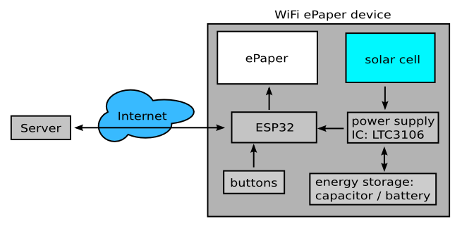
The device has 3 buttons. If two buttons are pressed at the same time, the device starts as an access point. A smart phone or any other computer with WiFi hardware can then connect to it and configure the local WiFi access point SSID and password, and the server to which the device should connect, with a website that is served from the ESP32. After configuration, the device restarts and connects to configured server with the selected WiFi network. The rest is then configured with a web app at the server side.

In the webapp you can see which devices are connected to the server and you can assign names to it (e.g. "fridge", "living room", "shop-window"). The webapp shows the current displayed image of each device, which an be changed (text enter function, image import and freehand drawing). The devices polls once every hour, so the webapp shows the current status, with the old image and the new image (status display "pending"). When the device displays the new image, it returns an acknowledge so that you can see in the webapp when the new image is displayed.

More ideas and possible applications

- the device has 3 buttons, with which e.g. more than one image could be stored and displayed (show next/previous image)

- the buttons could trigger some action over the internet, like in combination with other home automation hardware, turn the light on/off, or it could be used as an alarm (contacts for the buttons are accessible and e.g. a reed switch could detect when a door opens)

- the ESP32 has a temperature sensor. This could be used to log the current temperature for each hour when the device polls the server to get new images.

- it could be used in a store to show special offers

- in general it could be used for any information display that doesn't need to be updated too fast, like opening hours for a shop or agency, together with useful current information

- alternative construction, to use more light from bulbs installed on the ceiling and for a more stable attachment for a fridge, or a shelf etc.:

license.txt

project license (BSD style: do whatever you want with it, but don't remove this file or my name)

plain - 1.08 kB - 04/29/2017 at 20:19

Download

  • 1 × E2417ES053 4.2” 3-Colors (black, white and red) ePaper
  • 1 × SLMD481H08L High efficiency solar cell module, optimized for indoor lights
  • 1 × ESP32 WiFi and Bluetooth module with user programmable microcontroller
  • 1 × LTC3106 Buck-Boost converter with maximum power point control functions

  • test board for bluetooth

    Frank Buss06/18/2017 at 20:53 0 comments

    For lower power consumption, I got some NRF51822-04 BLE4.0 modules modules. Bluetooth has the additional advantage that it can be used from a smartphone, so no extra server hardware is required (but optionally possible, with WiFi or ethernet connection). To test everything with the displays, I created a test board:

    This is how the board looks like:

    You can find all KiCad files and the CubeMX test project for the last test with the Crystalfontz display in the github repository. The board is 10 cm x 10 cm and would cost $76.25 at OSH Park, so I ordered it at seeed studio, for $4.90 for 10 boards. This means each board costs only $0.49, nice price. But for smaller board, OSH Park is less expensive because of the free shipping. The shipping cost at seeed was $12 with the "US GB DE AU Post" shipping option. But a board price of $1.69 is still very good.

  • STM32L433 and new display test

    Frank Buss06/17/2017 at 19:11 1 comment

    The new microcontroller on the breakout board is working, this is the test setup:

    All these wires are just for VCC, GND, and for the programmer and boot configuration:

    The 100 nF and 4.7 uF capacitors are directly soldered on the back between the pin headers. I configured the clock for the maximum allowed frequency with the internal oscillator, 80 MHz, and the power consumption was only 10 mA. The capacitors C1 and C2 depend on the crystal. I've used the ABS07-120-32.768kHz-T crystal from my RTC test for my Nixie tube clock, but omitted the capacitors and looks like it works, because they are in the picofarad range and my test setup might have already enough parasitic capacitance.

    After this I added a 32.768 kHz RTC crystal to pin 3 and pin 4 and configured the clock for 48 MHz and one pin for PWM output with timer 1 in CubeMX (don't forget to add a line like "HAL_TIM_PWM_Start(&htim1, TIM_CHANNEL_1)", otherwise there is no output), and I could measure a very accurate 24 MHz signal, better than 0.1 % accurate, the resolution of my scope.

    Usually you can't use the slow RTC clock to generate such a high frequency, but the internal high speed RC clock can be configured to get calibrated automatically by the low frequency RTC clock, which is a neat feature and eliminates the need for another external high speed crystal, even if you want to use the USB interface.

    Then I tested the new 128x296 3-color ePaper from Cystalfontz, 2.9". The website provides datasheets for the display, the breakout board and sample code for an Arduino. Unfortunately the naming of the pins different is different, but similar enough to guess what is meant:

    Arduino code breakout board PDF display PDF
    EPD_BUSSEL INT_SEL BS1
    EPD_READY BUSY BUSY
    EPD_RESET RESET RES #
    EPD_DC DC D/C #
    EPD_CS SS CS #
    (SPI transfer) MOSI D0
    (SPI transfer) SCLK D1

    Would make life easier if they would use the same name everywhere.

    The bus selection pin was always low in the source code (for 4 wire SPI mode), and on the breakout board is was soldered to GND anyway, so you can control the display with 6 pins from a microcontroller (and VCC and GND connected).

    This is how it looks like, with the demo code ported to the STM32 microcontroller:

    As you can see, the black fades to grey when the red image is updated, doesn't look as good as the 4.2" display from Pervasive Displays. But the image with the cat was the same grey when I got it, so I guess there is nothing wrong with my source code. I'll contact Crystalfontz, maybe they have better lookup table (LUT) data, because unlike the examples from Pervasive Displays, with this display from Crystalfontz the LUTs are sent from the application.

  • testing nRF24L01+ and more planning

    Frank Buss05/30/2017 at 18:52 0 comments

    As tested in the last log, the ESP32 needs a lot of power. With not too big solar cells, it might only update the display once every two hours. This is the reason I tested another wireless transceiver module, the nRF24L01+.

    I got some modules from eBay for or EUR 1.45 each and tried to test it with the example program with two Arduino nanos, as explained in his tutorial.

    But it didn't work. After what felt like reading all of the 122,000 Google search results for "nrf24L01+ not working", soldering extra SMD capacitors to the power supply pins, using an external power supply etc., it turns out the GettingStarted script doesn't work. But it works fine with the pingair_ack example. Power consumption was about 15 mA, with some short spikes when sending, much less than what the ESP32 needs. Was no problem to send to the next room, 5 m distance through one wall, with highest transfer power setting and 1 Mpbs. With 10 m and 2 walls sometimes there were (recognized) transfer errors, but it still worked.

    Unlike the ESP32, there is no programmable microcontroller on these modules. I plan to use a STM32L433CCT6 microcontroller for it. The 64 kB SRAM is sufficient to buffer a whole image for the 4.2" black/white/red display and it has very advanced power saving modes. While testing the LTC3106 power supply IC, it didn't work when starting from 0 V. With this new microcontroller it should work: The power good pin of the power supply IC can hold reset down until the voltage has reached a good level, and when the microcontroller starts, I can further measure the voltage of the backup capacitor and the solar cell, while running in low-power mode, to determine if there is enough power to do the wireless transfer. I already soldered it to a breakout board:

    This would allow a use-case that @Acube asked for: a slim and compact wireless ePaper display with a 2" display, which can be updated from a RF24L01+ module that is connected to a RaspberryPi (or to an ESP32). The RPi can be powered somewhere central in the house with a wall wart and it could update multiple displays as well, or read many sensors over the low-power wireless connection.

    I also got some cheaper and smaller displays from Crystalfontz to play with:

    This allows to build very compact wireless display modules.

    So the plan for the next steps is to modularize the design: The display modules will have a common interface to use whatever display is best for a given project. Then either an ESP32 can be used to control it, or an nRF24L01+ with the STM32L433 microcontroller and a sender module somewhere. The power supply can be a solar cell with all required voltage regulator chips, which I will build as a separate reusable module, or simply a battery or a wall wart, depending on your project.

  • power supply tests

    Frank Buss05/20/2017 at 20:19 3 comments

    So I bought this shiny LTC3106 power supply IC (costs EUR6.69 at Digikey) and it looks like it has all I need: peak current 650 mA, more than enough for my ESP32, and goodies like Maximum Power Point Control (MPPC) to get the most out of my solar cell. I soldered the IC on a breakout board, this is the final test setup:

    But it didn't work. The ESP32 module started but restarted all the time shortly after starting. There were many problems. First I used the solar cell at the Vin pin, as an example in the datasheet says, and a 15 F super cap for Vstore. But in the fine print of the datasheet you can see that the peak current for Vstore is 200 mA, so should be no problem, right? But the valley current limit is only 70 mA for Vstore. It is 400 mA for Vin, but no way I can get this from the solar cell and I can't add the super cap to the Vin input, because then the MPPC wouldn't work.

    And there was another problem: Even if I could have managed somehow to get the full current from the super cap, it has an ESR of 30 ohm, so e.g. at 3 V the max possible current would have been 100 mA.

    This was a fail, I guess I can't use the LTC3106. The only nice thing about it was the MPPC function, which worked as expected. I connected 1.5 meg ohm to GND from the MPP pin and the MPP voltage was about 2.5 V, the best voltage for my solar cell as you can see in my previous log, and it could charge the capacitor at Vstore to 5 V.

    Next I measured the current of the ESP32 while downloading an image and showing it on the e-paper, because I was suspicious why it resetted. The datasheet says 160 - 260 mA when sending with high data rate and max output power, and for receiving only 80 - 90 mA. But looks what I measured:

    I used the μCurrent, 1 mV is 1 mA. As you can see, there are spikes of more than half an amp! I guess the datasheet averaged the current consumption, or maybe I did something wrong when measuring it? But no way that I can do this with the LTC3106 or the super cap with the high ESR.

    But the solar cell charging part worked, so I changed the circuit: Now the LTC3106 charges only a different super cap, 5 F and 130 mOhm ESR (this one), which now is connected to Vout and I wired the programming pins of the LTC3106 to charge it to up to 5 V. For testing I added a linear regulator from this output (an MCP1703), to create the 3.3 V for the ESP32. Now it was possible to charge the new super cap and the ESP32 could load a new image and then go to sleep again. This is the charging curve with the solar cell and about 300 lux:

    As you can see, it charged the 5 F capacitor with more than 0.3 V in about 2 hours. When I clicked the reset button on the ESP32 to wake it up from sleep and load a new image, the voltage dropped to 3.58 V. So with this setup it is possible to update the display once every 2 hours.

    But this wan't the last problem: it didn't work from 0 V. When I discharge the capacitor and it starts charging it, the ESP32 starts drawing more current then the charging current at about 2.1 V and the voltage stays there. But the ESP32 module doesn't start at this voltage, it draws only current. When I hold down the reset button, the charging continues, so looks like this is a problem of the ESP32: it doesn't really work with slow rising supply voltages.

    Next I'll try to build my own voltage regulator circuit, using a low power PIC microcontroller to do all the controlling in software, and external FET switches and inductors. The reason for this is because the LTC3106 is too expensive, and it doesn't even fully work as I need it. And then I would need another expensive switching regulator to create the 3.3 V from the 5 V (the linear regulator I used now is just for testing, it wastes half of the energy). I stored the solar cell energy in a 5 V capacitor, because then the stored energy is higher and it needs longer to drop below what the next stage gets needs for minimum voltage, but this might change when I build my own regulator, because there are more good...

    Read more »

  • testing the new 4.2" black-white-red ePaper display

    Frank Buss05/06/2017 at 11:49 4 comments

    I got the breakout board for the new 4.2" black/white/red ePaper display, thanks to @jarek319 for the initial Eagle circuit and initial layout. I did the layout again, using all 0805 components. If you want to build your own, this is board from @oshpark and this is the Digikey cart to populate 2 boards, and including one display.

    The firmware for the new ESP32 is in the github repository of the ePaper project. It is based on the http_request example project and the Arduino script from this project, ported to the ESP32 framework. Some sample images are also there, together with the convert.py script to convert your own PNG files to the BIN file format used by the firmware. To compile the project, you need to install the IDF framework and toolchain first, as described here. After starting, the firmware loads image.bin from a webserver, then goes to deep sleep mode and waits for a reset.

    This is how it looks like:

    The new firmware doesn't use the NodeMCU project for using Lua with the WiFi module anymore. There is a development branch of the NodeMCU project for the ESP32, but still many libraries missing and not much RAM left. Even after reducing RX and TX buffer etc., I get a out of memory error if I try to allocate a 50 kB string or more in Lua. The reason might be that the new IDF framework needs more memory than the old for the ESP8266, and Lua needs memory, too, even when only loading the libraries, because they are not in flash, but loaded to RAM. And probably because of the reduced RX and TX buffers, I got timeout messages and canceled transfers for larger files (the 30 kB binary image files). The Hello World IDF example app, I could allocate up to 280 kB and with the new firmware, using just C and the IDF library, the image is loaded always, without timeouts.

    High resolution photo of the test setup:

  • Coffee status display and notifier idea

    Frank Buss05/04/2017 at 18:21 2 comments

    @morganrallen suggested an interesting application for it, for showing how fresh coffee is. After 3-4 hours coffee tastes pretty bad, even when on a hot plate. The idea is to press a button when new coffee is brewed, which then will display the current time on the display. When someone gets coffee, it is visible when it was brewed. The server application can notify interested people when new coffee is ready, or when it is time to make new coffee, and the server could trigger a new image on the display to show this as well. Different strengths could be displayed as well: Press one button for light and another button for strong, and the display shows different images. Probably the cheaper 2.9" display would be sufficient for such an application, which means the cheaper ESP8266 could be used as well instead of an ESP32.

  • solar cell tests and bigger display

    Frank Buss04/29/2017 at 20:08 0 comments

    For the solar cell, I bought this one, optimized for indoor use. The datasheet says max power is 714 mW. Of course, this is in full sun light with 100,000 lux. I tested it in my living room with not very bright artificial light for worst-case condition (my lux meter shows 200 lux). With this I can get get about 5 mW out of it.

    The interesting thing about solar cells is that they have a max power point. If you use a lower resistor as a load, the current increases, but the output power measured in watt gets lower below some resistor value. But if you increase the resistor too much, the output power gets lower again. There is a sweet spot for the maximum output power. For determining it I used my decade resistor box:

    Together with my multimeter, I tested it for different loads and noted the measured values in a spreadsheet (see here in Libre Office format). This is the result:

    As you can see, the maximum power is at about 2.6 V, with about 5 mW output power. I tested it for a brighter light, about 700 lux, and the maximum output power point was at the same voltage. Output power for this light is 6.2 mW. I used a LED flashlight for it, and looks like the solar cell couldn't use the wavelength of it as good, I would have expected more.

    I found a nice chip, which is designed to be used with solar cells and other such renewable energy source, the LTC3106 ( https://www.digikey.de/short/3nzcm2 ). With this chip it is possible to configure the voltage at to get the max power from the attached solar cell. This is called maximum power point tracking, MPPT, see here for details. It can also charge an attached battery or storage capacitor and use this automatically, when the light goes off. The efficiency is about 90% at 2.6V input voltage. If we assume even worse lights, e.g. 100 lux, we might have 1 mW available power, at a regulated output voltage of 3.3 V.

    I plan to use a bigger display than the 2.7" display of my first test, this 4.2" ePaper display. The ESP8266 doesn't have enough memory to buffer a frame, so I bought an ESP32 for it. I can already compile NodeMCU from source for it from the dev branch of the github repository and it runs. With WiFi activated it needs about 110 mA at 3.3 V. In deep-sleep mode I measured about 5 μA. The LTC3106 needs 2 μA quiescent current.

    Let's say worst case would be 10 seconds to start the module, connect to WiFi, download a new image and update the ePaper. The ePaper needs about 8 mA max current (of course, only when updating, it doesn't need any power for displaying content), so this would be 118 mA total, which means 390 mW. If we have always light, it would therefore be possible to use a duty cycle of 1:390. This means 3900 seconds off and 10 seconds on, which means we can update he display once per hour. When in deep sleep mode, together with the voltage regulator, the circuit needs less than 10 μA, which is 0.033 mW and can be ignored for the calculation, because the solar cell provides more than 1 mW.

    The ESP32 could measure the output voltage of the solar cell, so that the display doesn't get updated at night, but the battery or super capacitor can be charged, for maybe even shorter update rates. Or the update rate can be adjusted, depending on the charge state of the storage capacitor. But the conclusion is, that the project is feasible.

    Now I'm waiting for the breakout board to test the new ePaper, already ordered at OSH Park:

    Then I have all components to build a complete prototype.

  • first working prototype

    Frank Buss04/15/2017 at 00:06 0 comments

    I finished the port of the Raspberry Pi source code for the ePaper, as a module for the nodemcu-firmware project. I forked the original repository and added it as the Lua module "epd", see here:

    https://github.com/FrankBuss/nodemcu-firmware

    Then I installed the Mosquitto MQTT broker and wrote a Lua script for the module, that subscribes to the topic "display". The messages are interpreted as links to binary files which are loaded from a webserver and then displayed on the display, see init2.lua for the details in the new github repository for this project:

    https://github.com/FrankBuss/wifi-epaper

    With the Mosquitto test client I can send messages to the module from the PC, for example to load the image wifi-epaper.bin:

    mosquitto_pub -t "display" -m "wifi-epaper.bin"
    

    See the instructions on this website for details how to setup your own MQTT broker and for some explanations how to use it from Lua. The bin files are located on the webserver and are created with the test.py Python script from PNG images. The nodemcu_float_master_20170414-2230.bin file is the precompiled firmware image for the NodeMCU module, with the new epd Lua module.

    You can see the connecting scheme in the LibreOffice spreadsheet pins.ods on github. It gets quite complicated with all the different internal and external names. A spreadsheet is very useful for such a task so that you don't get lost.

    This is how it looks like when it is running:

    The current consumption in idle mode is still quite high with about 22 mA and some peaks from time to time, maybe I can find some sleep mode for the module, it doesn't need to react immediately. When receiving a new image and updating the display, it needs up to 80 mA (at 3V) for some seconds. But it is possible to run the NodeMCU module with less power, if you don't need immediate updates of the display, but poll it like every minute.

  • NodeMCU Lua string length limit

    Frank Buss04/14/2017 at 18:44 0 comments

    So I ported the C code from the Raspberry Pi library for the e-paper to the NodeMCU firmware. The source code didn't look very nice, I refactored and cleaned it a bit. I'm using strings for the binary image data, because this needs less memory than arrays in Lua. But I get "string length overflow" error.

    Turns out the default max string length in Lua for NodeMCU is 4096 bytes, and of course Murphy says I need 5808 bytes to store an image for my e-paper. But at least it can be changed with collectgarbage("setmemlimit", kilobytes) at runtime. Too bad there is only about 40 kB usable SRAM. I guess sooner or later I need to buy an ESP32, which has 520 kB.

  • collecting all the parts

    Frank Buss04/07/2017 at 16:56 0 comments

    So I dug up the display which I used 3 years ago, and the test image I uploaded with my Raspberry Pi project for another project I was planning, is still as clear as on the first day, and there was no power for these 3 years. That's amazing!

    Next for fast prototyping, I'll try to connect it to my NodeMcu module. This is a nice little ESP8266 WiFi module, which can execute Lua code, even over the internet. This makes development really easy and turnaround time fast, as I demonstrated here

View all 10 project logs

  • 1
    Step 1

    NOTE: these build instructions are for the first prototype with the ESP8266 and the 2.7" ePaper display. Will be moved later to another project, and the instructions here will be updated for the new ESP32 module and the new 4.2" ePaper.

    Build a new NodeMCU firmware

    NodeMcu has a lot of modules you can use, as you can see in the documentation:

    https://nodemcu.readthedocs.io/en/master/

    If you buy a NodeMcu module from eBay, chances are good that it comes with an old version and not with all modules you might need. So for the latest version and with all the goodies you need, it is best to compile your own firmware.

    The easiest way to do this is to use some cloud build service, as described on this page:

    https://nodemcu-build.com/index.php

    You can stop reading now if you use this service.

    But you can compile it from source as well. You can do this with a Docker image:

    https://hub.docker.com/r/marcelstoer/nodemcu-build/

    Docker is a nice system to create runtime environments with all the programs and libraries inside your OS. There are many different environments. To quote the webpage:

    Docker containers wrap up a piece of software in a complete filesystem that contains everything it needs to run: code, runtime, system tools, system libraries – anything you can install on a server. This guarantees that it will always run the same, regardless of the environment it is running in.

    If you've ever tried to setup a cross-compiler environment, you know how much work this can be, and chances are good that you break something other on your system. Docker solves all these problems.

    I'm using Debian Jessie as my main working operating system. Unfortunately it is not just "apt-get install docker" to install the Docker environment, and there is even another package named "docker", which makes it a bit confusing, but there is a manual at the Docker homepage how to install it and you need to to this only once:

    https://docs.docker.com/engine/installation/linux/debian/

    Obviously you don't want to do "apt-get remove docker", but the rest worked. This were my steps:

    sudo apt-get install apt-transport-https ca-certificates curl software-properties-common
    curl -fsSL https://download.docker.com/linux/debian/gpg | sudo apt-key add -
    sudo add-apt-repository "deb [arch=amd64] https://download.docker.com/linux/debian $(lsb_release -cs) stable"
    sudo apt-get update
    sudo apt-get install docker-ce
    "docker-ce" is the free community version of docker. There are instructions for Windows and Mac, too. After the installation you can check that it works with "sudo docker run hello-world" on Linux.

    Now you can install the NodeMcu Docker build environment:

    git clone https://github.com/nodemcu/nodemcu-firmware.git
    sudo docker pull marcelstoer/nodemcu-build
    cd nodemcu-firmware
    docker run --rm -ti -v `pwd`:/opt/nodemcu-firmware marcelstoer/nodemcu-build

    If you want to enable different modules, change the file "app/include/user_modules.h" and recompile your image with the last "docker run" command. The result is in the "bin" directory. There are two version, one integer and one float version, which determines what number type Lua uses. I use the float version, because this is the default in Lua and makes programming easier. The image name in my case was "nodemcu_float_master_20170410-1703.bin".

  • 2
    Step 2

    Flash a NodeMCU firmware image

    For flashing a new image, I use esptool. Plugin your NodeMCU module to an USB port, clone the esptool project and flash your firmware. Usually a new device will appear, like /dev/ttyUSB0. Step by step:

    git clone https://github.com/themadinventor/esptool.git
    cd esptool
    sudo python2 ./esptool.py --port /dev/ttyUSB0 write_flash 0x00000 ../nodemcu-firmware/bin/nodemcu_float_master_20170410-1703.bin

    (if there is an error "ImportError: No module named serial", then do a "sudo python2 -m pip install pyserial". If you have only Python 2.x installed, you can use "python" instead of "python2", this is just my system, where I have Python 3.x installed, too. Don't ask how long I needed to Google for all the errors and to have both versions of Python installed in parallel)

    Flashing needs less than a minute and the output should look something like this:

    esptool.py v2.0-beta2
    Connecting....
    Detecting chip type... ESP8266
    Uploading stub...
    Running stub...
    Stub running...
    Attaching SPI flash...
    Configuring flash size...
    Auto-detected Flash size: 4MB
    Flash params set to 0x0040
    Compressed 436208 bytes to 279594...
    Wrote 436208 bytes (279594 compressed) at 0x00000000 in 24.6 seconds (effective 141.8 kbit/s)...
    Hash of data verified.
    
    Leaving...
    Hard resetting...
    
    You can test it with "minicom --device /dev/ttyUSB0 --baudrate 115200". You might need to disable hardware flow control (the usual Telix commands: ctrl-a, o, "Serial port setup", F and G for disabling hardware and software flow control). Hit the reset button on the module (small button near the USB connector) and you should see something like this:
    NodeMCU 2.0.0 build unspecified powered by Lua 5.1.4 on SDK 2.0.0(656edbf)
    lua: cannot open init.lua
    > 
    
    It has a Lua REPL, which means you can execute commands from the minicom terminal, which is nice for fast prototyping and testing things:
    > = 1+2
    3
    > = wifi.sta.getip()
    192.168.1.123   255.255.255.0   192.168.1.1
  • 3
    Step 3

    Install a Lua script

    If you want to install a Lua script, which is started when the module starts, you can write this in a file called "init.lua". With the luatool.py you can upload it to the NodeMCU module:

    git clone https://github.com/4refr0nt/luatool.git
    python luatool/luatool/luatool.py --port /dev/ttyUSB0 --src init.lua --dest init.lua --restart
    You need the git clone only once. Sometimes the luatool script doesn't work. Reasons for this could be that you have still minicom open in another terminal, or you need to reset the module and start the script again. Note: if there is an error in init.lua, the module might get into an infinite reboot loop. To fix this, you can re-flash the firmware image, which deletes all scripts.

    This is an example script, which loads another script init2.lua from a webserver and executes it:

    function executeString(s)
        local fun = loadstring(s)
        fun()
    end
    
    function stripHeader(s)
        local pos = string.find(s, "\r\n\r\n")
        return s:sub(pos + 4)
    end
    
    function runScript(host, url)
        receivedPage = ""
        conn = net.createConnection(net.TCP, 0) 
        conn:on("receive", function(conn, data) receivedPage = receivedPage .. data end)
        conn:on("disconnection", function(conn, data) pcall(function() executeString(stripHeader(receivedPage)) end) end)
        conn:connect(80, host)
        conn:send("GET /" .. url .. " HTTP/1.1\r\nHost: " .. host .. "\r\nConnection: close\r\n\r\n")
    end
    
    wifi.setphymode(wifi.PHYMODE_N)
    wifi.setmode(wifi.STATION)
    wifi.sta.config("SSID","PASSWORD")
    wifi.sta.eventMonReg(wifi.STA_IDLE, function() print("IDLE") end)
    wifi.sta.eventMonReg(wifi.STA_CONNECTING, function() print("CONNECTING...") end)
    wifi.sta.eventMonReg(wifi.STA_WRONGPWD, function() print("WRONG PASSWORD!!!") end)
    wifi.sta.eventMonReg(wifi.STA_APNOTFOUND, function() print("NO SUCH SSID FOUND") end)
    wifi.sta.eventMonReg(wifi.STA_FAIL, function() print("FAILED TO CONNECT") end)
    wifi.sta.eventMonReg(wifi.STA_GOTIP, function() runScript("192.168.11.27","init2.lua") end)
    wifi.sta.eventMonStart()
    Replace "SSID" and "PASSWORD" with your WiFi SSID and password and the address "192.168.11.27" with your webserver address. For faster development it is nice to install a local webserver. Then you can edit the init2.lua file locally on your PC or Mac, and to test it just hit the reset button on the module, which reloads the script. This helps also if you have errors in your Lua script, because you don't need to re-flash the firmware in this case. Leave minicom open to the serial port and you will see the output of the script (with "print") and when it reboots. Once your script works, you can rename it to init.lua and permanently install it on the module with luatool.py.

    Note: the default max string length is 4096 bytes in Lua, which is the limit for your script. You can change this with 'collectgarbage("setmemlimit", 64)' in your init.lua to e.g. 64 kB. But when WiFi is connected etc., you have only about 40 kB available RAM. If you need more: the ESP32 has 520 kB RAM.

View all 4 instructions

Enjoy this project?

Share

Discussions

((( TTN_Berlin ))) wrote 12/29/2017 at 20:16 point

very interesting project. add LoRaWAN pls

  Are you sure? yes | no

oshpark wrote 10/18/2017 at 05:23 point

I'm wondering if the FancyEPD library might work with this display: https://github.com/zkarcher/FancyEPD
-Drew Fustini

  Are you sure? yes | no

Stephen Holdaway wrote 05/24/2017 at 05:43 point

Have you experimented with different waveforms for the display update? I'm working on a project with a few eink/epaper displays at the moment (7.5", 4.2", 2.13"), and having a fast, non-flashing display update is something I've been looking at (the display is in sight all the time and updates quite frequently). Curious if you've considered or tested anything in that space.

  Are you sure? yes | no

Frank Buss wrote 05/24/2017 at 06:15 point

This would be great, but I don't know how to change the waveform. The SPI protocol is very high level ( https://github.com/FrankBuss/wifi-epaper/blob/master/firmware/main/epd.c ) and all commands are undocumented.

  Are you sure? yes | no

Markus wrote 05/24/2017 at 07:09 point

Who is the manufacturer of your displays? Some of them are not allowed to use partial updates due to legal reasons. Also there is a reason why full updates (the flashing ones) are the standard. The optical performance is really bad if you only use partial updates.

  Are you sure? yes | no

Frank Buss wrote 05/24/2017 at 08:03 point

Both displays are from http://www.pervasivedisplays.com The black/white display allowed partial updates, not just by line, but you could individually say per pixel if it should change to white, black or leaved unchanged. Looks like the new black/white/red display allows only full updates, but at least black/white and red are two different commands and send sequences.

  Are you sure? yes | no

Markus wrote 05/24/2017 at 08:07 point

With 3 different particles the drive pattern is much more complicated, so I guess you can't even do partial updates there. In the industry the use case for these displays is price tags and shelf labels so they don't need them.

  Are you sure? yes | no

Stephen Holdaway wrote 05/24/2017 at 08:00 point

Hmm, your code looks suspiciously similar to mine - command bytes, pin names from the display, protocol etc. Looking at the display on my desk vs. your photos, I think this is possibly the same display, though I have a black and white one, not black/white/red. Here's a chunk of my code that I haven't pushed to Github yet:

https://gist.github.com/stecman/847dd15e80ba292c29da28ba62e972fe#file-gdepaper-h-L8-L20

The display I bought was GDEW042T2 from Good Display on AliExpress, which appears to have been de-listed (at least the listing I bought from). Here's a picture:

https://imgur.com/a/aGiFd

Digging around on the internet a bit, I found the datasheet for the display (Good Display's website), and the datasheet for the controller (can't remember where). They're each a little inconsistent, but together there's enough to get most things working:

https://archive.stecman.co.nz/files/datasheets/GDEW042T2/

The guy I was emailing at Good Display was a bit cagey when I asked about a specification for the LUT/waveform registers the datasheet mentions. 

> Firstly, waveform is not must to drive a e-paper.
> Only at specific environment where temperature is changed widely.
> We will supply it to customer when you have bulk purchase.

etc

  Are you sure? yes | no

Markus wrote 05/24/2017 at 08:13 point

Judging from the controller's datasheet it seems to support partial updates. The question remains if the display manufacturer put the waveform in the controller's flash.

  Are you sure? yes | no

Stephen Holdaway wrote 05/24/2017 at 08:13 point

Looks like your breakout board is also very similar to mine (9 pin out, 0.47ohm resistor, 3 schottky diodes, N-channel FET, bunch of :caps)

https://imgur.com/gallery/drpbQ

(though mine is a single sided home-made thing)

  Are you sure? yes | no

jareklupinski wrote 05/18/2017 at 19:25 point

Looking forward to seeing your solar charging solution :) The BQ25something TI chip I've been using "locks up" when I'm refreshing my screen ( it can only source 50mA peaks, with an esp8266 that's already too much ), and I've been playing with the LTC3105 to disappointing results...

  Are you sure? yes | no

Frank Buss wrote 05/19/2017 at 07:59 point

Add a bigger capacitor?

  Are you sure? yes | no

jareklupinski wrote 05/19/2017 at 11:02 point

I'm already up to 2.5F! ( not kidding i slapped literally all my caps together just to try, but i think at that point the load just to charge them freaks out the regulator )

I'll try to use the Enable inputs on the ltc, maybe disabling it while my program is refreshing, then enabling it before going to sleep will keep it happy

  Are you sure? yes | no

Frank Buss wrote 05/19/2017 at 18:11 point

Sounds strange, especially because the LTC3105 allows a Li-ion battery at the output, so 2.5 F should be no problem. And the datasheet says 400 mA. Do you have a circuit?
I'm trying the LTC3106. A bit pricey, but it does everything for you: separate port for a battery/super cap, switching between two different inputs, charging the battery, automatically selecting  buck or boost converter mode etc.

  Are you sure? yes | no

jareklupinski wrote 05/23/2017 at 18:18 point

Sry i realized I was a bit ambiguous: the TI bq25570 was the one with the 50mA limit that I kept running into.

The LTC was coaxed into behaving properly by shutting it down when the ESP was awake; I'll see if adding an inductor will let me tie the SHDN line :)

  Are you sure? yes | no

Frank Buss wrote 05/23/2017 at 11:00 point

While testing my setup, I noticed that the ESP32 draws up to 500 mA. And another thing I tried: I decoupled the output of the power supply IC with a coil. So Output of the power supply, goes to something like a 1000 uF capacitor to GND, then through a 10 uH coil (high speed, like used in the ePaper driver), and then in some big capacitors. This reduced the spikes a lot, and maybe helps you, too, to avoid freaking out your regulator. But it will introduce some ripple on the power supply input of your ESP8266, but this should be ok, because it has a wide range of supply voltage.
But I think in the end a really powerful regulator would be better, which can handle like 1 A, and then placing the big, low ESR, capacitors on the regulator input.

  Are you sure? yes | no

jareklupinski wrote 05/23/2017 at 18:15 point

I need to keep inductors in my head as a solution... I'll get a large coil from digikey and let you know! thanks :)

  Are you sure? yes | no

jacksonliam wrote 05/08/2017 at 22:41 point

This is very cool and something I'd thought should be possible myself. 

That display is a little pricey, it's more than a brand new e-reader! I wonder if a kindle replacement screen could be used? 

  Are you sure? yes | no

Frank Buss wrote 05/08/2017 at 23:00 point

I think I've seen a Hackaday.io project which uses a kindle replacement display, they are cheap from Aliexpress etc. And @oshpark did a breakout board for a 2" ePaper display, which costs less than $10, can't find it at the moment. For many application such a smaller display would be still useful.

  Are you sure? yes | no

oshpark wrote 05/08/2017 at 23:44 point

This is the project with the Kindle screen:

https://hackaday.com/2017/04/20/e-ink-display-driven-diy/

The 2.15" epaper is in this project:

https://oshpark.com/shared_projects/Wk76kUK3

  Are you sure? yes | no

Kirk Northrop wrote 05/08/2017 at 20:23 point

Hi Frank - this is awesome - but I can only see a link to a board and a list of parts, and not an explanation as to which part is which value. Is there a chance you could point me to this please?

  Are you sure? yes | no

Frank Buss wrote 05/08/2017 at 23:05 point

Do you mean the breakout board for the 4.2" display? Right, I noticed that in the original schematic there was values at the parts. I added this to the Eagle circuit diagram. Still work in progress, I'll add a better explanation later, but this is the parts list for the last working breakoutboard:

C1       4.7uF               CAPACITOR_NP_0805    C0805            MF_Passives               1
C2       4.7uF / 50V         CAPACITOR_NP_0805    C0805            MF_Passives               1
C3       4.7uF               CAPACITOR_NP_0805    C0805            MF_Passives               1
C4       100nF               CAPACITOR_NP_0805    C0805            MF_Passives               1
C5       4.7uF               CAPACITOR_NP_0805    C0805            MF_Passives               1
C6       1uF                 CAPACITOR_NP_0805    C0805            MF_Passives               1
C7       4.7uF               CAPACITOR_NP_0805    C0805            MF_Passives               1
C8       4.7uF               CAPACITOR_NP_0805    C0805            MF_Passives               1
C9       4.7uF               CAPACITOR_NP_0805    C0805            MF_Passives               1
C10      4.7uF               CAPACITOR_NP_0805    C0805            MF_Passives               1
D1       MBR0530             DIODES_SOD-123       SOD-123          MF_Discrete_Semiconductor 1
D2       MBR0530             DIODES_SOD-123       SOD-123          MF_Discrete_Semiconductor 1
D3       MBR0530             DIODES_SOD-123       SOD-123          MF_Discrete_Semiconductor 1
J1       MF-CON-2.54mm-01x09 CON_01X09_PTH_2.54MM PTH_2.54MM_01X09 MF_Connectors             1
L1       IFSC-1515AH-01      INDUCTOR             INDUCTOR-SRP4020 SparkFun-Passives         1
R1       0.47? / 1%          RESISTOR_0805        R0805            MF_Passives               1
U1       DMN3067LW-7         N-CHANNEL_FET        SOT323           MF_Discrete_Semiconductor 1
X1       FH12-34S-0.5S"      FH12-34S-0.5S"       XF3M-34          con-hirose                1

  Are you sure? yes | no

Kirk Northrop wrote 05/09/2017 at 06:43 point

Thank you very much!

  Are you sure? yes | no

Similar Projects

Does this project spark your interest?

Become a member to follow this project and never miss any updates