Close
0%
0%

Desk Buddy

A small device that lets work colleagues know if you'll be at your desk today so they know if they can sit there.

Similar projects worth following
The Desk Buddy is an ESP8266 based device with two LEDs (Red and Green) and an 4-line LCD that will be permanently sit at my desk. A connected app will allow me to remotely set Desk Buddy to light up green when I plan on coming into work and red when I won't be in. The LCD will display an associated text message when the status is changed to help those not familiar with this scheme.

Throughout the day Desk Buddy will display useful information on the LCD such as current weather, expected travel time to home, stock prices and news headlines. It will also briefly pop up bad dad jokes and my tweets.

Desk Buddy will include a security measure to alert me and surrounding office if it is picked up. It will be powered by USB plug pack with a backup battery. If it is moved, a motion sensor will trigger a process that sends a push notification to the connected app and sounds a built in alarm. The battery will ensure it can continue to operate even when unplugged.

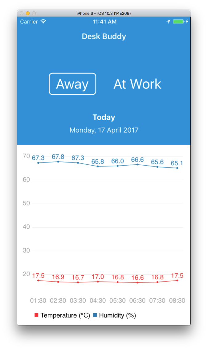
When I arrive in the office, a beacon will be detected by the app to then notify Desk Buddy. Desk Buddy will then know to initiate any sequences such as a greetings, flashing with "excitement" that I'm here.

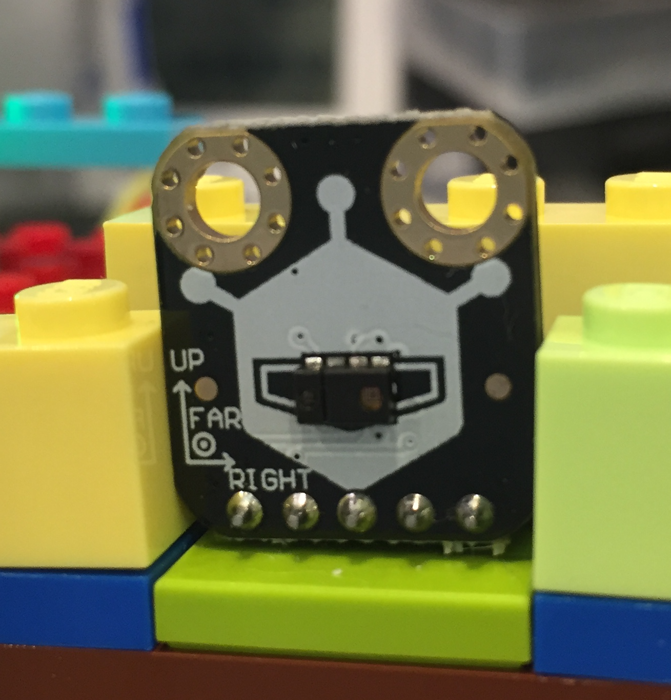
A sensor may also be used to detect if someone is sitting at my desk when I'm not in so that Desk Buddy can switch to Visitor mode.

  • 1 × NodeMCU ESP8266 Primary processing module
  • 1 × HCSR501 PIR Passive Infra Red Motion Detector Used to detect if the device is lifted from my desk
  • 1 × Blue 20x4 LCD Module with I2C backpack LCD module includes an I2C backpack
  • 1 × RGB LED
  • 1 × DHT22 Temperature and Humidity Sensor

View all 10 components

  • IBM Watson Internet of Things

    Tony Kambourakis05/14/2017 at 02:23 0 comments

    IBM Watson IoT is used to communicate with Desk Buddy via MQTT. The Watson IoT service was created via Bluemix as a service.

  • Gesture Sensor Idea

    Tony Kambourakis05/14/2017 at 02:04 0 comments

    As Desk Buddy will be displaying various messages throughout the day for both the owner and the visitor it may be useful to navigate back to an older message.

    Using the principle of identifying a solution looking for a problem, the APDS-9960 Gesture Sensor board presented itself as an interesting way to interact with the device for visitors. The mobile app should allow for the owner to view a timeline of messages displayed by Desk Buddy.

    The visitor would use hand gestures in front of the 9660 to "swipe left" or "swipe right" between messages in the timeline. A "near" gesture may trigger a menu that could allow for the user to perform certain functions such as "Say hello to owner".

    The 9660 includes an I2C interface and an interrupt pin. As the 9660 I2C interface supports 3.3V it can be connected directly to the SDA (D4) and SCL (D5) pins on the NodeMCU. I2C is a bus based communication that allows for multiple devices to be connected to the same lines. Each device has an address that is used to tell the device when to "latch" on to the SDA line.

    SparkFun provides an Arduino library that was modified by Jonathan Ulmer to work with the ESP8266.

    More to come.

  • Mobile App

    Tony Kambourakis05/14/2017 at 01:43 0 comments

    The baseline of the Desk Buddy mobile app is complete and allows the user to change the current status (Away or At Work) and view the last 8 temperature and humidity readings in a graph.

  • Motion Sensor

    Tony Kambourakis05/14/2017 at 01:40 0 comments

    The motion sensor detects the presence of a visitor on a day that I am not in the office. This will trigger a welcome message and appropriate informational feeds to the display throughout the day with a reminder to clean up the desk at the end of the day.

    The HCSR501 PIR Passive Infra Red Motion Sensor is powered by 5V but includes a 3.3V output level.

    The motion sensor output is connected to the NodeMCU D7 pin. The pin is set as an input and attached to an interrupt that detects a rising edge.

    #define MOTIONSENSORPIN D7 // D7 = GPIO13
    
    void setup() {
      pinMode(MOTIONSENSORPIN, INPUT);
      attachInterrupt(MOTIONSENSORPIN, motionSensorActivated, RISING);
    }
    
    void motionSensorActivated() {
      motionSensorDetected = true;
      motionSensorDetectedCount += 1;
    }

  • 20x4 LCD

    Tony Kambourakis05/14/2017 at 01:28 0 comments

    This Blue 20x4 LCD module supports bidirectional I2C, is reasonably priced and works well with NodeMCU. The I2C support is provided by the attached PCF8574T backpack module. The supply voltage is 5V and the SDA/SLC lines are

    The PCF8574 data sheet states in the DC characteristics section that the minimum HIGH level input voltage for SCL and SDA is 0.7 times the supply voltage. This equates to:

    As the NodeMCU output is 3.3V a logic level shifter is used to convert the 3.3V to 5V levels.

    The LCD is controlled via the following pin assignments:
    LCD I2CNodeMCUGPIO
    SDAD4GPIO2
    SLCD5GPIO14


  • RGB LED

    Tony Kambourakis05/14/2017 at 00:41 0 comments

    The RGB LED includes a pin for each colour and a ground. Each colour pin was connected to a port on the NodeMCU:

    RGB LEDNodeMCUGPIO
    R (Red)D3GPIO0
    G (Green)D1GPIO5
    B (Blue)D6GPIO12

    A 470Ω resisters was used for each colour.

    The pins were assigned to status definitions in the code to make it easier to set their status:

    // PIN definitions
    #define OWNER_STATUS_IN 0 // D3 = GPIO0
    #define OWNER_STATUS_OUT 5 // D1 = GPIO5
    #define OWNER_MESSAGE  12 // D6 = GPIO12
    
    pinMode(OWNER_STATUS_IN, OUTPUT);
    pinMode(OWNER_STATUS_OUT, OUTPUT);
    pinMode(OWNER_MESSAGE, OUTPUT);

    To set the LED to Owner Status IN mode, switch ON the desired colour and switch OFF the other colours.

    digitalWrite(OWNER_STATUS_IN, 0); // switch off
    digitalWrite(OWNER_STATUS_OUT, 1);
    digitalWrite(OWNER_MESSAGE, 0);

  • Temperature and Humidity Sensor

    Tony Kambourakis05/14/2017 at 00:36 0 comments

    The DHT22 is a popular and simple to use temperature and humidity sensor comprising a single Data pin with VCC and GND.

    The DHT22 is connected to the NodeMCU via the D2 pin (GPIO4) and initiated with the following code:

    // Temperature and Humidity Sensor (DHT22) Configuration
    #define DHTPIN D2
    #define DHTTYPE DHT22
    DHT dht(DHTPIN, DHTTYPE);
    This code utilises the DHT sensor Library (ID 19) installed within Platform.io. Note that there are a few DHT22 libraries, I found this one worked best for me with the DHT22 and NodeMCU under platform.io.

    When reading the temperature and humidity it is important to check that actual values are returned using isnan().

    void readDHTSensor() {
       // reading DHT22
    
      h = dht.readHumidity();
      t = dht.readTemperature();
    
      // Check if we fail to read from the DHT sensor
      if (isnan(h) || isnan(t)) {
        Serial.println("Failed to read from DHT sensor");
        publishDebug("Failed to read from DHT sensor");
        //TODO: Do more here
      }
    
      hic = dht.computeHeatIndex(t, h, false);
    }

  • Schematic

    Tony Kambourakis05/14/2017 at 00:21 0 comments

    After using Fritzing for a while I found it crashing far too many times and switched to EasyEDA. The circuit includes a NodeMCU with a 20x4 LCD interface through a logic level shifter. The DHT22 provides temperature and humidity readings with the RGB LED as a status indicator and the HCSR505 PIR Motion Sensor to detect the presence of someone at my desk when I'm not there.


View all 8 project logs

Enjoy this project?

Share

Discussions

Similar Projects

Does this project spark your interest?

Become a member to follow this project and never miss any updates