 Douglas Miller
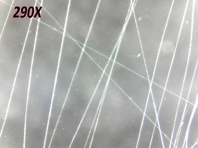
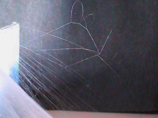
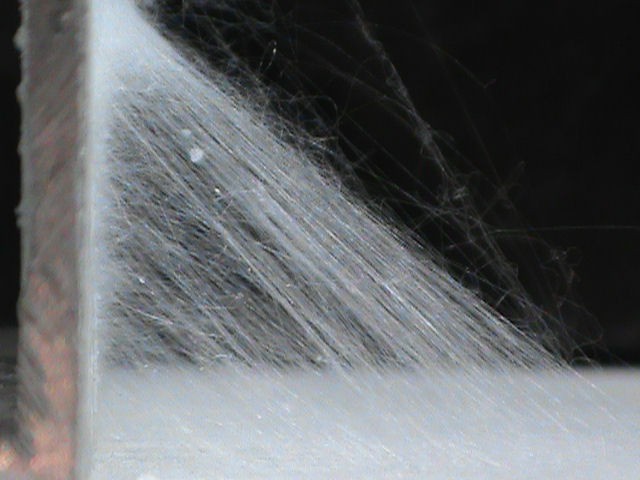
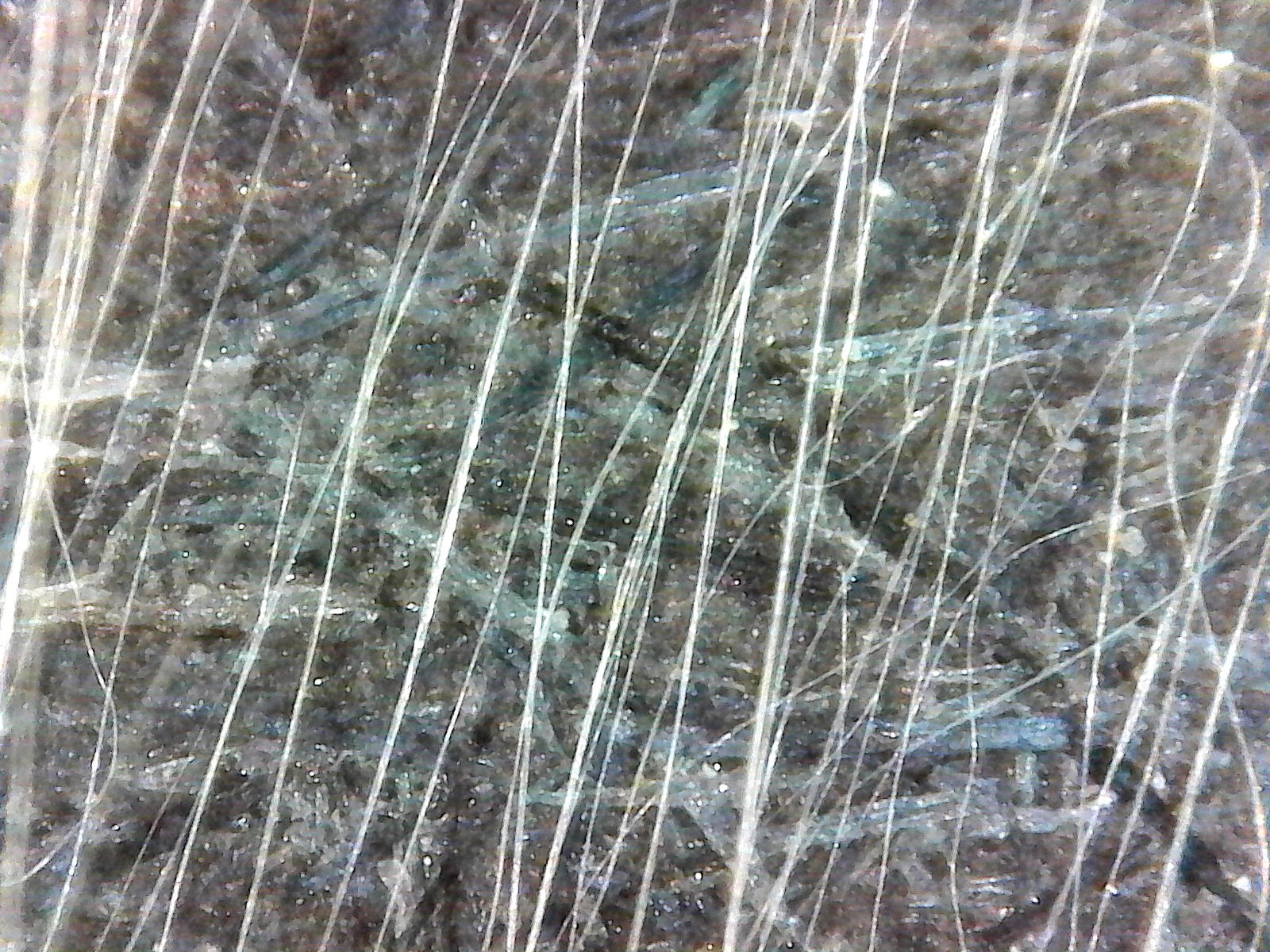
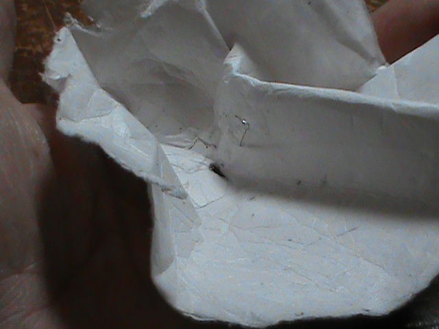
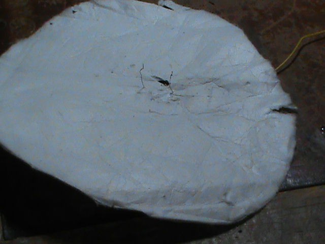
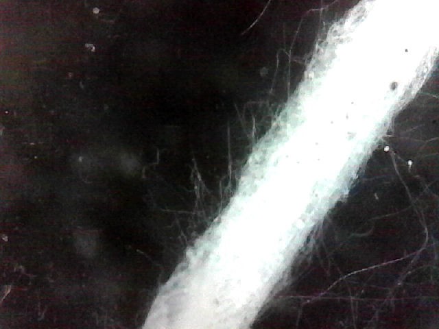
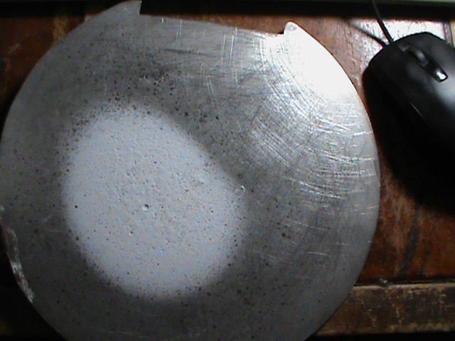
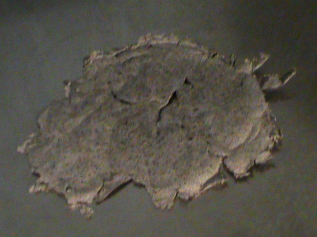
When materials are electrospun, a strong electrical field pulls and stretches the droplets as they are extruded. This stretching can bring the fibers produced down into the nanometer range. I've gotten a lot in the micron range already, and there are smaller ones in there but I can't prove it (yet!) because my microscope simply can't magnify them that much. At those scales some materials exhibit behavior different from other forms of the material. PVDF is one such material, and one I'm really looking forward to working with. As a force sensor it exhibits a force several times greater than the piezoelectric sensors we mostly use today. Think prosthetic hands with a thin sensor built right into the finger tips.
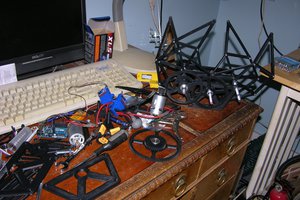
I've made some pretty good progress over the winter, and I'll be showing some of the results in the logs.
This project is open source, including all CAD drawings, STL files, firmware and control software. I want people to build it, and hopefully contribute what they learn back to the community.
Discuss the challenge the project addresses:
With new materials come new uses and new challenges, as far as makers and hackers go. Many of those new materials operate differently, and present new abilities, depending on how and at what scale they are made. From the force detection of PVDF to aligning carbon nanotubes end to end, electrospinning gives those materials new uses. Electrospinning is not new, by any means, but it's usefulness in taking advantage of those new materials has never really been put to the test for Citizen Scientists. What's needed is to kick start a community of explorers in this area around a common base that everyone who joins in knows will produce repeatable and shareable results. That's the challenge.
Discuss how the project will alleviate or solve the problem that the project addresses:
Without a common base for everyone to work with it'll stay in that condition. This machine gives everyone the base to start experimenting from, while making their progress shareable to others. It also will, I hope, introduce electrospinning to anyone who has never heard of it before. Maybe it will even get them to start experimenting on their own and share what they come up with.
Discuss how the project might be world changing:
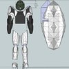
This project can change the world, not by itself, as such. But by giving everyone a common starting point and a community of users of hackers, makers and Citizen Scientists to work from, it can lead to advances in materials and their uses in many different fields. Those include, but are certainly not limited to, force sensors, carbon nanotube electrodes for higher capacity batteries, super capacitors, energy production, lighter materials with greater strength, wearables and biomed applications. I'm also looking into using it to make artificial muscles.
Really, this is one of those 'limited only by our imagination' type of things.
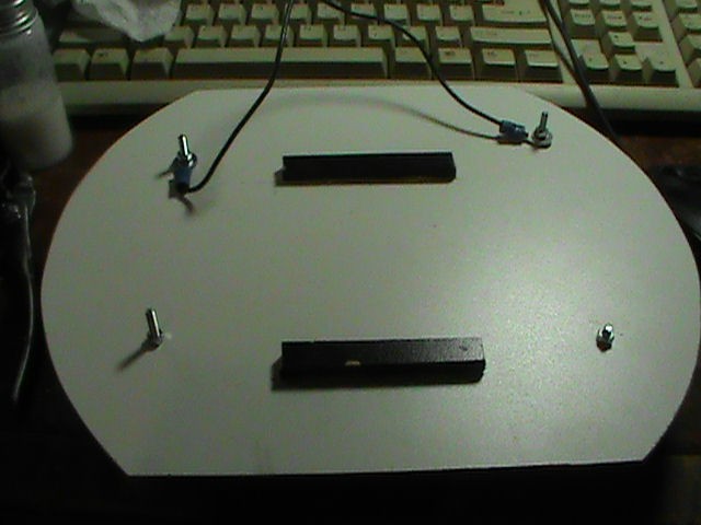
Publish at least one (1) image illustrating how the project might be used. This may be a sketch, schematic, flow chart, rendering, or other type of image.:
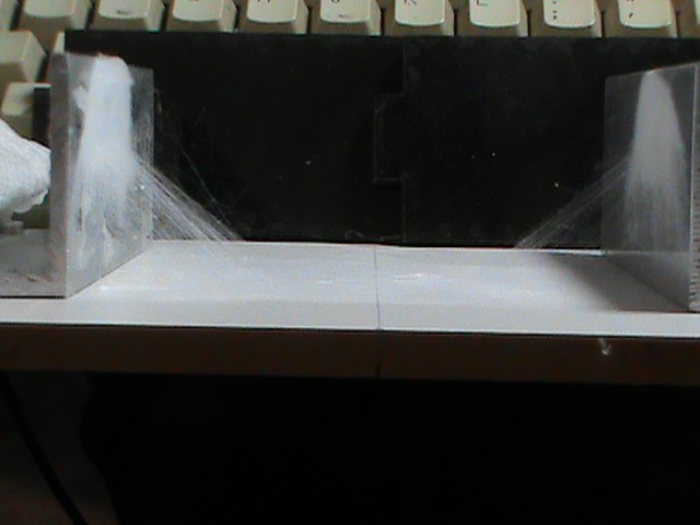
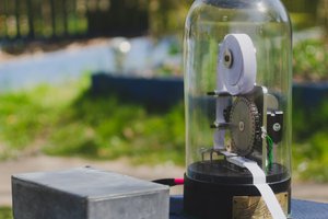
Done. There are many images and videos in the projects log files showing it working, how to use it, and the results.
Link to any repositories (e.g., Github):
Done. All the files are available at https://github.com/dougmsbbs/OpenESpin
The files are also available right on the projects Hackaday project page.
Document all open-source licenses and permissions as well as any applicable third-party licenses/restrictions:
All machine hardware and software licensed as Creative Commons Attribution-ShareAlike 3.0
Seriously, use it, abuse it, work with it, change it, improve it, and share what you discover. All I ask for is credit where credit is due. (but a link back to the projects website would be nice!)
There are no...
Read more »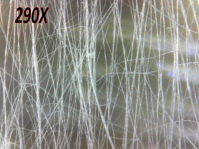


 secretbatcave
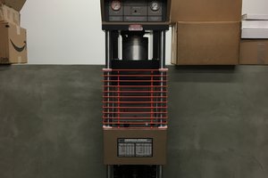
 Supplyframe DesignLab
 Morning.Star
I know this project hasn't been active in most of a decade, but AFAIK it's still the only reasonably well documented open source electrospinning machine out there. My makerspace has been slowly collecting up the pieces to build this thing. We've got almost all the parts now. If we can get it running, we'd like to carry on your work.
Does anyone following this project have any recommendations for a 30kV adjustable power supply? I'm a novice and don't really know what I'm looking for. How do these things even work? Am I meant to plug it into a typical U.S. wall outlet, or does it get wired to the 12V/30A power supply? Everything I'm seeing for sale is either ~$100 or ~$5,000... Are the way cheaper ones missing some crucial component that I just don't understand?