0%
0%
Mouse Aid
With this companion your mouse will be able to perform fine and precise movement in drawing applications
 danjovic
Become a Hackaday.io member
Already have an account? Log in.
Just one more thing
To make the experience fit your profile, pick a username and tell us what interests you.
Pick an awesome username
hackaday.io/
Your profile's URL: hackaday.io/username. Max 25 alphanumeric characters.
Pick a few interests
Projects that share your interests
People that share your interests


 Utkarsh Tiwari
 Eric Hertz
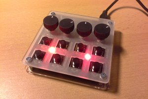
 Stefan Lochbrunner
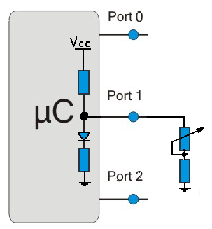
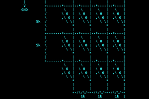
Are these diodes, not resistors ?