Close
0%
0%

D1 Mini Matrix Deluxe Shields

Shields for the D1 Mini ESP8266 board using the ISSI chips

Similar projects worth following

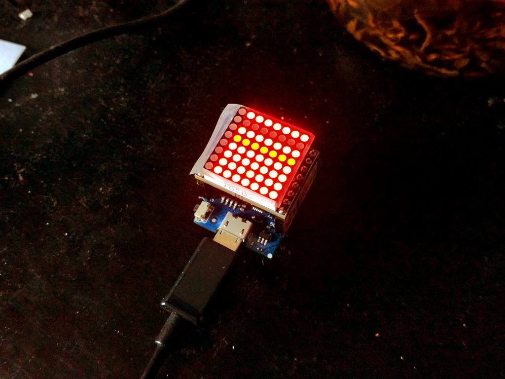
When I ordered the matrices for the #D1 Mini Matrix Shield project, I found a number of cool matrices that couldn't be driven by the venerable HT16K33 chip that I used there. I went to search for a chip that could handle them, and was pointed to the IS31FL37* family of chips produced by ISSI.

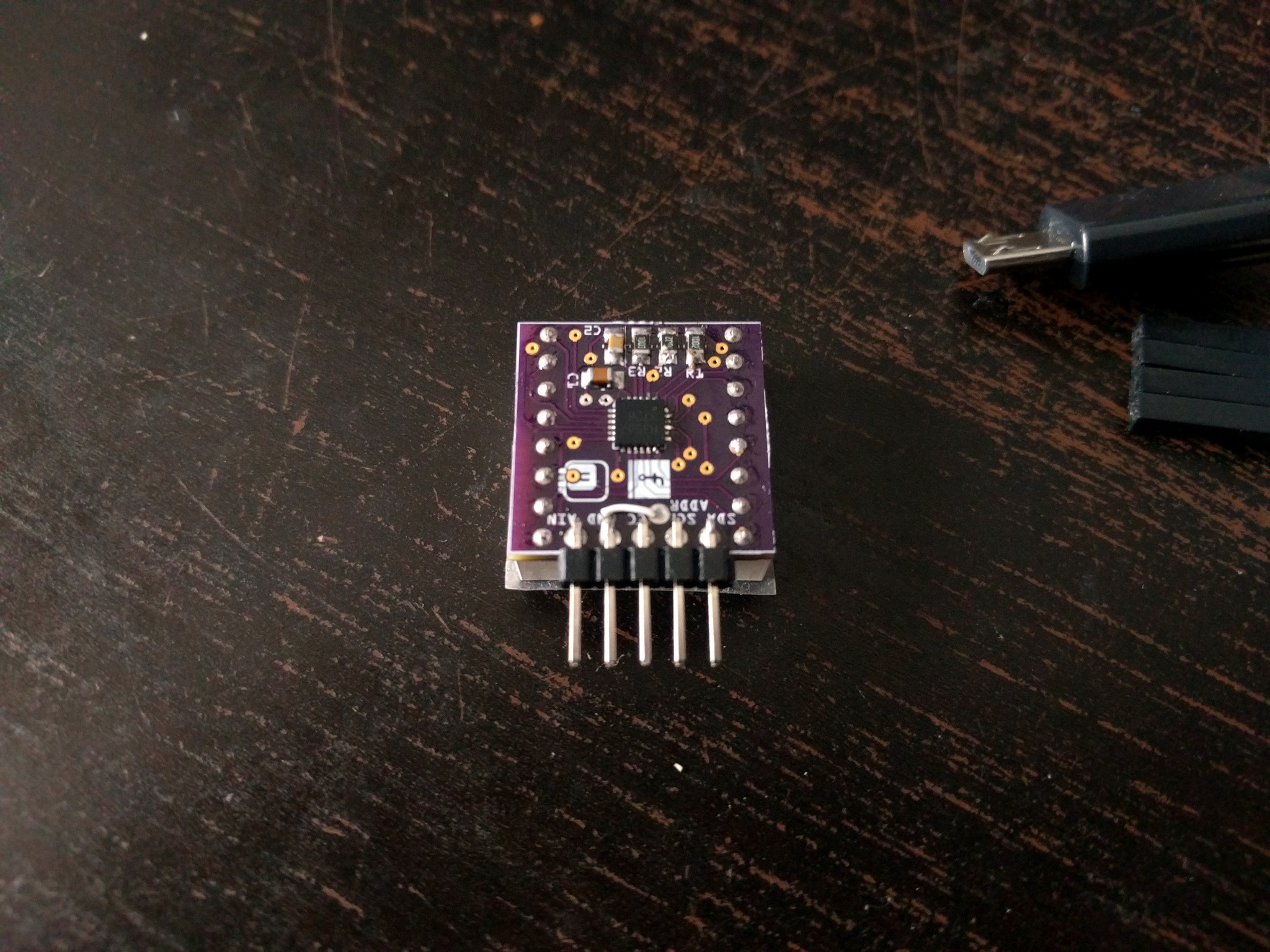
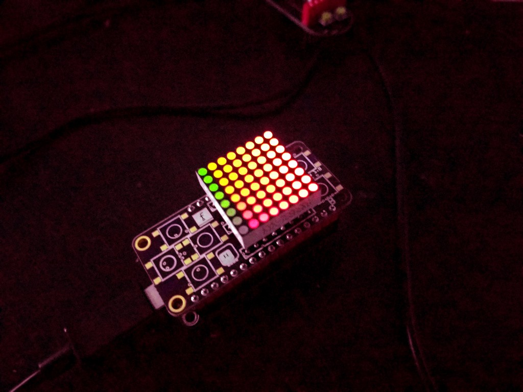
Those chips are interesting for a variety of reasons. There are versions for charlieplexed displays, and for driving two matrices connected in reverse to each other, and for various sizes of regular matrices. More importantly, they can control the brigtness (or color) of each LED individually, and they often have interesting additional effects built-in, such as automatic animations, per-pixel blinking and "breathing", and some can even modulate the brightness according to music or other analog input. They are also much more modern -- they come in very small QFN packages and operate on 3.3V logic.

I requested some samples of those chips, and I will try to design and build some matrix shields using them. I also plan to do some more interesting things with them, but we will see how that works when I actually try.

8x8-matrix-issi.zip

Gerber files for the 8x8 monochrome matrix breakout board.

Zip Archive - 44.06 kB - 05/09/2017 at 21:28

Download

matrix-issi.fz

Fritzing design for the 8x8 monochrome matrix breakout board.

x-fritzing-fz - 706.93 kB - 05/09/2017 at 21:26

Download

d1-mini-matrix-issi.fz

Fritzing design for the 8x8 monochrome matrix shield.

x-fritzing-fz - 857.42 kB - 05/05/2017 at 12:54

Download

d1-mini-8x8matrix-issi.zip

Gerber files for the 8x8 monochrome matrix shield.

Zip Archive - 32.87 kB - 05/05/2017 at 12:53

Download

  • Equalizer on the IS31FL3728

    deʃhipu07/23/2017 at 23:07 0 comments

    I recently got a hot air rework station (a cheap Chinese one), which allowed me to revisit some of my failed assemblies with the QFN chips, and fix them. Yes, the problems I had were partly due to missing filtering capacitors, but also due to bad soldering. With the hot air I'm getting 100% success rate, which is a 100% improvement from the manual method. Yay.

    One of the boards I re-did was a breakout for the IS32FL3728 chip with the audio pin broken out. Since I also had a small microphone breakout at hand, I decided to try the equalizer mode of that chip. There are some good and some bad news.

    The good news is that it works pretty nicely, blinking the LEDs in time with the sound. The bad news is that since I completely scrambled the order of rows and columns, for easier routing, and then fixed id in software, the hardware equalizer, which doesn't know anything about my row/column remapping, doesn't really look like a proper equalizer.

    So I sat down and re-designed the breakout, paying attention to keep the rows and columns in order. Turns out it was still possible to route everything (I think I'm getting better at it), and the new breakout is now ordered:

    It's exactly the size of the matrix, and I got it on a thin PCB. But the best thing is thet there are some empty areas left on that board (where the sheep and the Fritzing logo are), and I could probably fit a small microcontroller in there, that would just put the chip in the equalizer mode, and a small microphone. Just add a coin battery, and you have a fancy wearable equalizer display... I need to do some testing when the boards arrive, but it seems promising.

  • A Quick Tour Around the IS31FL373x Chips

    deʃhipu07/02/2017 at 22:26 3 comments

    There is a whole family of those, and they are all controlled in a similar way. Of course all the details are in the datasheets, and in theory this is all the information you need, but in practice I think it's useful to have a general bird's-eye view of the whole thing.

    The chips are controlled over I2C and I'm not going to explain that. Uncharacteristically, it has two additional pins related to the I2C protocol, apart from the usual SDA and SCL: those are the IIC-RST, which can be used to reset the part of the chip that handles communication, in case your bus gets stuck in some weird state preventing communication, and VIO, which sets the voltage that you want to use for the communication. I usually just pull the IIC-RST down and the VIO up.

    The higher-level protocol is also quite simple. You have 8-bit registers with b-bit addresses, divided into pages. To read or write a register from the current page, you simply write that register's number, and then either read with a repeated start or write. That's pretty much standard. Changing a page is bit more involved, because it's apparently potentially dangerous: first you need to unlock the page register by writing the magic value 0xc5 to the register 0xfe, and then you can write the page number to the register 0xfd.

    There are four pages.

    Page 0 is dedicated to configuring which LEDs are being used, and to reading results of the open/short detection. At the minimum you need to write 1s to the bits corresponding to the LEDs that are actually connected to the chip (your matrix may be smaller than the chip's maximum). You only do it once at the beginning.

    Page 1 contains information about brightness of each individual LED. That's where you actually draw your pixels. Of course, the default brightness is 0, so you need to write something there to actually see anything.

    Page 2 controls blinking, or rather "breathing", as they call the fade-in fade-out animation that you can set on any of the individual LEDs, in 3 different variations of timing. You don't need to touch anything here. Oh, and for this to have any effect, you need to set the B_EN bit in the register 0x00 on page 3.

    And finally page 3 is configuration. At the minimum, you need to write 0x01 to the register 0x00 here to enable the chip, and some value to the register 0x01 setting the global brightness (because of course it defaults to 0 and you wouldn't see anything). The rest is about configuring the blink timings, pull-up and pull-down resistors on the LEDs, and a software reset -- not that interesting.

    So the workflow of the driver is usually as follows:

    1. Set which LEDs you are using by writing to registers on page 0.
    2. Switch to page 3.
    3. Enable the chip and set the global brightness.
    4. Switch to page 1.
    5. Actually draw your graphics by writing to the registers on page 1.

    That should get you started. Of course, there are lots more small details and possibilities there.

  • Grayscale 14x11 Matrix

    deʃhipu06/19/2017 at 17:49 0 comments

    The IS31FL3733 has double the pins of IS31FL3736, so you get double fun! This board was also finished and assembled for some time, but I couldn't get it to work. Today I checked dug it out to try the capacitor trick, but it already has the decoupling capacitor. But once I had it out, I did some more experimenting and sure enough, I had the SDA and SCL pins swapped on it!

    This board was pretty hard to route -- it's a lot of pins, and it's not like they are arranged with any logic. In the end I couldn't find a way to route the last 4 traces, so I just made two 4-pin headers, and then connected them with wires. It works, and that's what counts.

    The colors in the photos are of course all wrong -- because the camera sees colors differently than human eye. In reality all the pixels are red, with different brightness -- not yellow.

    I guess now I need to write the code for playing a movie on this, or at least some animated gifs...

  • Grayscale 7x11 Matrix

    deʃhipu06/19/2017 at 14:59 1 comment

    The third chip that I got from ISSI is IS31FL3736. It's very similar to the IS31FL3733, except it only drives up to 8×12 LEDs. That's perfect for those 7×11 LED matrices that I got!

    I actually designed that shield a while ago, and assembled it when it came. But it didn't work, at least not reliably -- the chip would sometimes be visible on the I²C bus, and sometimes not, and sometimes it would start behaving weird after some time... I put it all to my poor soldering skills and the really tiny QFN package, and gave up on it for a while.

    Yesterday, after debugging some problems with the IS31FL3733 on the #PewPew FeatherWing, which were solved by adding a decoupling capacitor across the power, I decided to dig out the old board and try adding a decoupling capacitor to it too. And what do you know, it works perfectly fine after all!

    The PCB is here: https://oshpark.com/projects/luMANBrm

    And the updated MicroPython library for driving it: https://bitbucket.org/thesheep/micropython-is31fl37x/src

  • Smaller 8x8 Matrix Breakout

    deʃhipu05/09/2017 at 21:24 1 comment

    The shields are nice, but not everybody has a D1 Mini, and not everybody wants to put that matrix on top of their dev board. Sure, you can just use wires for the shield, but with such a small and convenient chip, it makes sense to make an even smaller breakout board -- one that you could tile easily. So I made one that is exactly the size of the matrix:

    I soldered the pin header sideways here, but you can also solder it normally, and then you can tile the boards easily. I also broke out the address pin this time, so you can change the I2C address of the board by connecting it to one of the other pins (you get 4 different addresses this way).

    There is also the audio pin, which you can use to control the brightness or to feed the built-in equalizer. I will be experimenting some more with that once the microphones arrive.

    I have added the design files and gerbers to the download section, and you can also order the board from @oshpark here: https://oshpark.com/shared_projects/jGebL1gK

  • 8x8 Matrix Shield Design

    deʃhipu05/05/2017 at 13:01 0 comments

    The final PCBs for the 8x8 matrix shield based on the IS31FL3728 chip arrived, and I verified that all the connection are now correct and working. You can download the design files and the gerbers in the "files" section above.

    Here is the schematic (the connections for the matrix itself are left as ratlines, for clarity):

    And here's the image of the PCB (I changed the colors from default yellow on orange):

    The bill of materials is as follows:

    • the PCB
    • the IS31FL3728 in a QFN package
    • 3x 10kΩ 0805 resistor
    • 2x 100nF 0805 capacitor
    • 1x 1µF 0805 capacitor
    • 1x 220nF 0805 capacitor
    • 1x 8x8 mini LED matrix with anode rows and cathode columns

  • PewPew FeatherWing

    deʃhipu05/03/2017 at 07:52 0 comments

    Apart from making those breakout boards for the D1 Mini (and the corresponding libraries), I also decided to use the IS31FL3733 chip in an expansion board for the Adafruit Feather boards, turning them into a simple game console. However, since that's a little bit different, I made a separate project page for that at #PewPew FeatherWing.

  • Bi-color 8x8 Matrix

    deʃhipu04/28/2017 at 22:48 0 comments

    After the IS31FL3728 chip, I tried its larger cousins, but I'm still struggling getting them to work. They are in 40- and 48-pin QFN packages, which are pretty hard to solder by hand (in fact, it might be impossible without a hot air gun and/or a reflow oven). But one of them, the IS31FL3733 also comes in a TQFP package, and I got one. This one is too big to fit on a D1 Mini shield, but I made something else:

    (Note that the colors are smooth and perfectly fine in reality, but my phone camera can't handle them.)

    This project will have a page of its own soon, but for now it's a good testing platform for my code. So I made another MicroPython library, available at https://bitbucket.org/thesheep/micropython-is31fl37x that can handle both IS31FL3733 (for up to 12x16 matrices) and IS31FL3736 (up to 8x12 matrices).

    In the mean time, I'm going to work on those QFN chips, maybe I will manage to get them to work somehow. Maybe it's just time for me to invest in a proper rework station?

  • The 8×8 Monochrome Matrix Finished

    deʃhipu04/19/2017 at 19:42 1 comment

    Well, almost. There is going to be one more version of the PCB, because of course I swapped one of the rows with one of the columns of the matrix.

    You can also see that one of the rows has a cold joint in there, but that was easily fixed.

    I also wrote a MicroPython library for this matrix, which is available at https://bitbucket.org/thesheep/micropython-is31fl3728/src

    I will still need to update it to reorder the rows and columns to fit the reality -- but I will do that once I get a final working PCB.

  • Custom Footprints

    deʃhipu04/14/2017 at 22:30 3 comments

    I made the trip to the hackerspace and used their hot air gun, and desoldered/resoldered the chip properly. I can now confirm that the resistors that I removed from the example schematic in the datasheet when designing that version of the PCB were in fact necessary for the chip to function. Who would have thought! Oh well, I just need to wait for the other version of the PCB, with all the resistors, to arrive.

    In other news, I also received the PCB for the 7x11 matrix and the IS31FL3736 chip. Unfortunately, there is a small problem with the QFN footprint that I used (instead of making a custom one based on the datasheet):

    Turns out that just taking a 36-pin QFN footprint and adding the pins to make it a 40-pin QFN footprint is not enough -- you also have to scale it down. I have now corrected all my QFN footprints for those chips to be exactly like in the datasheets, and re-did the PCBs. Of course it's another couple of weeks until they arrive...


View all 12 project logs

Enjoy this project?

Share

Discussions

Erik Rosengren wrote 04/16/2018 at 13:50 point

Thank you for awesome projects. I've ordered some 788AHG 20 mm 8x8 bi-color matrices together with some HT16K33 28SOPs. Looking at your pictures made me realize that I really want the individual dimming, so i'm looking at the IS31FL3737 now.

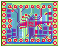
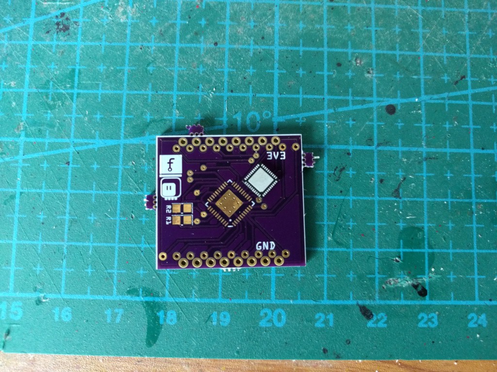
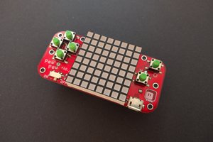
My big problem is that I want to fit everything within the area of the LED matrix (I'm making a LED matrix keypad). The added 8 pins in the middle gives me 7.5 mm room to fit the 5 mm driver, which might be impossible.

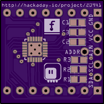
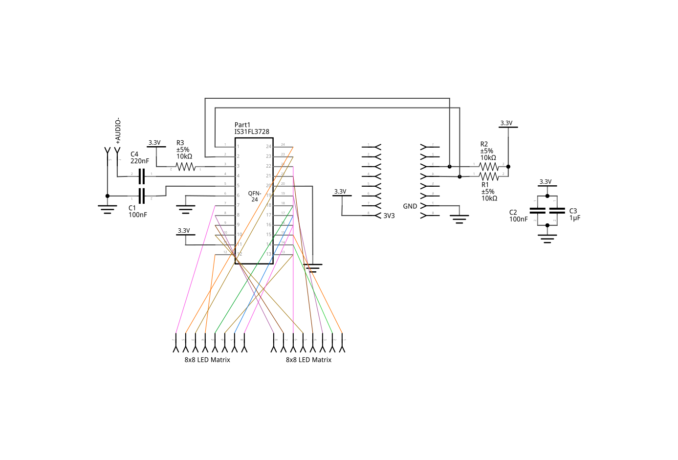
Do you want to share your Fritzing file (https://cdn.hackaday.io/images/931981491389033893.png) so I can try to fit it in?

  Are you sure? yes | no

Richard Milward wrote 06/19/2017 at 17:17 point

Where did you get the 7x11 matrix?

  Are you sure? yes | no

deʃhipu wrote 06/19/2017 at 18:02 point

Aliexpress, as usual. Search for 13117BS (make sure you don't get the 13117AS, it has wrong polarity).

  Are you sure? yes | no

deʃhipu wrote 05/27/2017 at 23:44 point

Oh, wow, nice! Thank you for the heads up. I have never heard about it before, but now I did some research and there is a log coming up about it soon.

  Are you sure? yes | no

Similar Projects

Does this project spark your interest?

Become a member to follow this project and never miss any updates