Close
0%
0%

PewPew FeatherWing

A shield for Adafruit Feather boards with buttons and a LED matrix display, for simple games.

Similar projects worth following

Game programming is hard. Sure, you can easily throw together something in RPGMaker, RenPy or Unity3D, and it's great -- but you don't actually know how it works inside. There is a certain skill required to go from scratch, write your own main loop, handle events, push the pixels, etc. Incidentally, the same exact skills are required when programming any other interactive system, such as a graphical user interface, an automatic appliance, a mobile art installation or... a robot! Those are going to be much more common in our lives soon. If we want to stay in control, we need to be able to program them ourselves, and for that we need those skills. They empower us and give us back the control over the technology.

One great tool for teaching it is PyGame -- which is a library, and not a game engine, so it forces you to attend to all those pesky details of game engine internals yourself. Which is a bit difficult, of course, but ultimately very useful. But even if you play with PyGame on the Raspberry Pi, it's still a very complicated and difficult to understand system. The learning curve is steep, and debugging is hell.

Enter MicroPython, and one of its flavors, CircuitPython. It's written by the people at Adafruit with the education in mind, but it runs on infinitely simpler devices than your average computer. Devices which you can't break easily, because reflashing the program will reset them to a known good state. Devices which run on batteries for hours, and which you can carry in your pocket. Devices, for which there is a plethora of add-ons and sensors that you could make use of in your game.

However, as of yet, there is no game library and/or add-on that would allow to easily create games in CircuitPython. This project is an attempt to fix this.

pewpewlite-4.0b_schem.pdf

Schematic for PewPew Lite 4.0

Adobe Portable Document Format - 1.75 MB - 10/15/2017 at 15:39

Preview
Download

pewpewlite-4.0b.zip

Gerber files for PewPew Lite 4.0

Zip Archive - 121.04 kB - 10/15/2017 at 09:01

Download

  • 1 × PCB https://oshpark.com/projects/Bvfn9hBI
  • 1 × HT16K33 28SOP
  • 6 × Tact switch 6x6x4.5mm
  • 1 × 1.9mm Bi-Color 8x8 LED Matrix, with common cathode (788AHG)
  • 6 × SMD 0603 Resistor 39kΩ

View all 8 components

  • Buttons

    deʃhipu07/18/2019 at 07:27 0 comments

    The buttons came today, so I finished it. It's not the prettiest soldering job, and the buttons are not quite aligned, but it works and I can move on.

  • D1 Mini Shield

    deʃhipu07/15/2019 at 20:46 0 comments

    I have been mostly working on the #PewPew Standalone recently, but some people still prefer the PewPew Lite version, mostly for its color display and ability to work with the ESP8266 Feather. So after I finally found reasonably tiny buttons for #D1 Mini UI Shield, I decided to also make a version of the PewPew Lite in form of a D1 Mini shield. As an additional challenge I wanted to make it electrically identical to the FeatherWing. After two nights, I had the design:

    It's not perfect. Ideally, all the resistors would be under the LED matrix, but there simply wasn't enough room to fit all the traces there. But I managed to do it, even if it required a thousand vias. I ordered the PCB from OSHPark, and promptly forgot about the whole thing.

    Today the boards came, so I assembled one. I found a bi-color matrix in my drawer, but I only found 3 of the buttons — I'm still waiting for the package with more of them. So I only soldered what I had, to test how the menu works:

    Since CircuitPython no longer supports ESP8266, I had to port the Pew library to MicroPython — that was easy enough, with just changing all the timing functions to use utime, and all i2c calls to use the machine module. After I did that, I wanted to upload the code to GitHub, but discovered that it's already there — I have ported it once already and forgot about it.

    Once the missing button arrive I will finish this.

  • Replaced by PewPew Standalone

    deʃhipu10/23/2018 at 16:14 0 comments

    While this still works and is fully compatible with all other PewPew boards, and while I still sell it on Tindie, check out the new devices over at #PewPew Standalone — they are bigger and cheaper, though no color display.

  • Making it Cheaper Again

    deʃhipu07/14/2018 at 14:58 0 comments

    The PewPew Lite FeatherWing is one of my favorite designs, and I think it's really great for learning programming games — actually better than the #µGame, because it's so much simpler. The shield itself is pretty cheap, too. Unfortunately, you still need to have a Feather M0 (or, even better, M0 Express) to use it, and that's actually twice as expensive as the shield itself. Add the LiPo battery to the mix, and you could instead buy an ODROID GO or something similar. This is problematic especially if you want to organize a workshop — you either make a workshop for the rich, or find a sponsor.

    I have already tried to lower the price of the whole thing by putting the microcontroller directly on the device — basically copying the Trinket M0 schematic for that — but the resulting device was pretty complex to make, and I was never quite happy with it. Plus, you still needed the LiPo battery and its charging circuit and all that.

    Today I sat down and redesigned the latest version of PewPew completely, using the knowledge I gained from µGame and from the #CircuitPython Badge to simplify it as much as possible, while still keeping its basic functionality. That's how I came up with PewPew 6.0:

    It's exactly the size of two AA batteries, because that's what it is going to be using for power. It uses the good old HT16K33 chip, just like the PewPew Lite, which simplifies things a lot. However, the buttons are handled directly by the microcontroller now, because to have them handled by the HT16K33, I would need six extra resistors, and I tried to minimize the parts count. To get rid of Shottky diodes or transistors for isolating the USB VBUS, I simply used the power switch to switch between the battery power and the USB power. I might even skip the voltage regulator and make it always run on battery power. Apart from that, there are the six buttons, the bi-color matrix, the SAMD21 microcontroller itself, two pull-up resistors for the I2C bus and two filter capacitors — that's it. Everything is routed on the top layer of the PCB (the bottom is one big ground plane), and all parts (except for the battery holder) are mounted on top, to simplify assembly. I'm using the QFN version of SAMD21, because it's slightly cheaper.

    I considered using other chips than the HT16K33 for driving the matrix, in particular, simple shift registers to do all the work in the microcontroller, but in the end the HT16K33 is cheap enough and does all the work for me. In the future, I might consider switching to charlieplexed SMD bi-color LEDs and driving them from the MCU pins directly — that would probably shave a few dollars from the BOM at the cost of more work with assembling it.

  • PewPew Lite Version 4.2

    deʃhipu05/08/2018 at 15:23 0 comments

    I had that version designed for quite a while, actually, and even the PCBs arrived and were lying there in a drawer — but I didn't have time to work on them, busy with other projects. Now I moved, and found the PCBs in a box (and @Benchoff mentioned PewPew in an article), and decided to assemble them and put up on sale on Tindie. So now there is a new version of the PewPew Lite on Tinide. For now I only made ten, because that's how many boards I had, but I already ordered some more, and more parts, so I will keep them coming.

    The new version comes with the matrix display already soldered, and with staggered holes for the pin headers — so that you can simply friction-fit them without soldering. The connection seems to be good enough, but if you experience problems, you can always solder them. There is still no socket for the battery — you will have to solder the leads directly if you add it. There is simply no room for it on this board.

    Also, you no longer can choose a color. They are all red. It was the preferred color anyways, yellow ones only got sold when the red ones ran out.

  • Version 5.1

    deʃhipu04/17/2018 at 22:03 1 comment

    I have been doing some spring cleaning, and found the PCBs I made for the version 5.1 of the PewPew, which I never actually assembled. That version is bigger than my previous attempts, and uses a larger, 3cm matrix. Since I will be soon going to work with that ISSI matrix driver chip again (for the #CircuitPython Badge), I decided to go ahead and assemble this after all. Here's the result, next to the PewPew Lite for scale (please excuse the flux stains):

    Unfortunately, I didn't actually find the source of those bi-color matrices with square pixels — the ones I have have round pixels, and this one is desoldered from Adafruit's backpack, because it does look much better. The new board does have sound, but lacks the battery charging circuit — I assumed it will be powered by a non-rechargeablecoin cell battery on the back. Unfortunately, I didn't test it first, and turns out that the non-rechargeable batteries simply don't have enough power for this to work.

    I don't currently plan on making any more versions of this, or on manufacturing this version — it's just something I wanted to finish. I will probably be making more of the PewPew Lite FeatherWings for sale, though, as there seems to be interest in those.

  • LAMEBOY Playing PewPew Games

    deʃhipu02/23/2018 at 11:12 0 comments

    I recently assembled a @davedarko's #LAMEBOY kit, and I wrote a simple library in MicroPython to handle all the hardware on the device. Then I thought, hey, this has buttons and display, I bet it could run PewPew games! So I ported the library to CircuitPython and added a small compatibility library for PewPew, and lo and behold, the games work!

    And since the ESP8266 has much more memory than the poort little SAMD21, you don't even have to precompile the libraries. It all fits with room to spare.

    All the code is available here: https://bitbucket.org/thesheep/circuitpython-lameboy/src/

  • The Aisler Saga, Part 2

    deʃhipu12/06/2017 at 21:27 2 comments

    A few weeks ago I found in my mailbox a strange box from Aisler I was a little bit surprised, as I didn't order anything from them since the last time, when I tried their service for the first time. The box contained another 3 PCBs of version 4.1, and a steel stencil for one side. A few days later another parcel arrived, with another 3 PCBs and a stencil for the other side. This would have been great, except at the moment I was already two versions further into the design, and the boards just added to the pile of the trash PCBs I will never use. Sigh.

    So I wrote @Felix Plitzko an e-mail, explaining that I don't really have the time right now to try those boards, that they are wrong version anyways, and that they should not send me anything without asking. I never got any answer to that e-mail, but no further packages arrived, so I guess I am good. I also promised to look at those boards and stencils at some point in the future, just to see how the service improved. So let's look at them.

    This is the back of the board, and the corresponding stencil. I have to admit that all the dense thin pads for the ISSI chip are exactly the same, and generally I can't see any problems with the solder mask or copper. The silkscreen is still a little low-res, but it's somehow much more readable. There outline of the ISSI chip is a bit broken on the silkscreen, but that might as well be a Fritzing bug — it has a lot.

    You can also see that the drunk German who is cutting out those boards with a hatchet got over his hangover from Octoberfest, but is still not very precise. What's worse, each of the PCB has those leftover tabs different — which I will get back to in a moment.

    As for the stencil, it looks correct at first, but if you look closely, there are three strange things. First, there are no pads for the USB socket. I suppose they got confused by all the vias I placed there for mechanical support, and skipped them. Second, there is no hole for the ISSI chip's heatsink. To be frank, I don't know if there is supposed to be one or not — I'm not familiar with stencil practice. Third strange thing is that there are holes in the stencil for the power switch's mounting holes. Am I supposed to put solder paste into them?

    Let's look at the other stencil:

    This one is much simpler and less mysterious. There is only one problem here, which is the missing pad for the "up" button. Interestingly, no holes for the power switch this time, even though, being holes, they are present on both sides of the PCB. I guess it's enough to fill them with solder paste from one side.

    Fine, so there are some mistakes in there. That happens, especially since I had no idea they are going to be making stencils out of my design, and so I didn't pay attention to take care of any details relevant to that. You would still think that they would put more care into checking their "demo" work.

    So let's try and actually use a stencil. I never tried one before, so I was curious. I choose the top one, with the buttons, because that part of my design didn't change much and I wouldn't be wasting parts soldering an old version of the project. Also, buttons are easier to recover.

    So first I had to somehow align the PCB with the stencil. On the movies I saw that you usually have your stencil taped by one side to something, then tape some stuff around your PCB to fix it in place in an aligned position. I couldn't get that to work, it was just too difficult to move the PCB under the template to align it. It would have been much easier if the template also had the mounting holes or something — but I guess then the solder paste would get into them.

    Eventually I untaped the stencil, aligned the PCB by holding both in my hands, and taped some stuff around the PCB to the template to fix the position. Success.

    Now try a second PCB, and... it doesn't fit. Because those hacked tabs are uneven, and give different spacing. So I would need to manually align every single PCB I wanted to use with this stencil,...

    Read more »

  • Sanity Check

    deʃhipu11/02/2017 at 10:41 1 comment

    It's important to periodically revise the project's goals, both to see if they are still relevant, and to adjust the course of the project to better fulfill them. It's time to do this for PewPew. I recently did that for PewPew.

    The last change in course of the project was almost two months ago, after the Mini Maker Faire Zürich, when I decided that while PewPew Lite seems functional enough, it costs up to $40 to get all the parts together — the feathers, the battery and the PewPew Lite itself. Then I identified the feather board as the most costly part of the whole, and one that I don't have any control over. So I decided to try and get rid of that part by designing a standalone version of PewPew.

    I have to note here, that nobody was complaining about the price, they were, however, complaining about the fact that they have to buy separate things in separate places. Making PewPew standalone would also solve that problem.

    I produced four different prototypes for that, with a design for the fifth already on my disk and prepared for ordering. I initially used a smaller PCB, but after struggling with fitting everything on it, I switched back to the Feather form factor, and after @davedarko recently pointed out that I can make it bigger and use the bigger LED matrices, I designed yet another version, shaped more like the GameBoy.

    But then, in the mean time, I also worked on #µGame — and I realized that the ST7735R 128x128 RGB display on it is cheaper than the IS31FL3733 chip I use for driving the LED matrix, not to mention the LED matrix itself. And it was trivial to make the PewPew games run on µGame too.

    Sure, the LED matrix has a lot of advantages compared to the TFT display. It has excellent brightness and viewing angles, while not using a lot of battery power. It's made of plastic, not glass, and therefore it's very hard to damage, even when carried in the pocket. Its low resolution and limited colors impose restrictions that stimulate creativity and make it actually much easier to finish the game. But the display also has advantages over the LED matrix. It's bigger, has more colors, lets me use cute graphics for the "pixels", doesn't require me to route dozens of tiny traces or solder TQFP48 packages with insane pitches, is very common and easy to source and looks more like a "real" game console. It also lets me display text in a readable form, which is great for things like error messages.

    I don't want to merge the µGame and PewPew into one project — PewPew has very well defined goals that are different from the "for fun" nature of µGame. But I think that it doesn't actually make much sense to have an "advanced" version of PewPew, when µGame exists. So I won't be ordering that last prototype. Instead, I made one last version of the PewPew Lite shield, with only one small change — replacing all the resistors on it with resistor arrays, reducing the number of parts from 17 to 11, and making it better suited for eventual fabrication. I will wait for it to sell out on Tindie, and order another batch, and in the mean time I will work on the workshops.

    Honestly speaking, PewPew Lite is really good for the goals of this project, and the standalone version doesn't really add much. And after looking into assembly services and the prices for them, I realized that I can't really make it much cheaper than the feathers — not so much that it will matter. Maybe I could get it down to $30 or $25, but I'm not sure it's worth it. And the extra features, like more colors and sound, are not really adding much to the project goals — they are more of a distraction.

    So I will stick to the PewPew Lite and work on the content from now on. And new features and developments are going to go into µGame, which is more of an experimental project, without clearly defined goals.

  • Version 4.2

    deʃhipu10/23/2017 at 23:48 2 comments

    After finding the reason for CircuitPython crashes in #µGame and getting the audio amplifier to work, version 4.1 has pretty much all the parts that I wanted to have. However, its physical layout is somewhat problematic, especially the rather large speaker smack in the middle of the board, which makes it hard to add a battery there.

    So I started working on version 4.2. So far I have the following changes:

    • Added guide holes for the USB socket.
    • Larger footprint for the flash chip, so that more chips can be used.
    • Smaller and cheaper reset switch.
    • Pads instead of holes for the battery connector.
    • Moved the audio amplifier circuit.
    • Moved the speaker to the front of the board, and used a footprint for really small SMD speakers.
    • Moved some components away from each other, so it's not as cramped.

    I'm still considering two more changes:

    • Add a voltage divider to an analog pin, for measuring battery voltage.
    • Move the charging circuit before the switch, so that charging is possible with the switch off.

    I think that 4.2 will be the last prototype, at least if everything works as expected.

View all 54 project logs

  • 1
    Solder paste for the buttons

    Heat the board a little bit with your hot-air station, and then apply the soldering paste on all the button pads.

  • 2
    Place buttons

    Place the buttons in they correct positions. Be careful to align them properly, as the surface tension of the solder will not be enough to move them.

  • 3
    Solder buttons

    Apply the hot air to solder the buttons. Be careful to not melt the plastic caps.

View all 23 instructions

Enjoy this project?

Share

Discussions

MagicWolfi wrote 07/16/2019 at 00:57 point

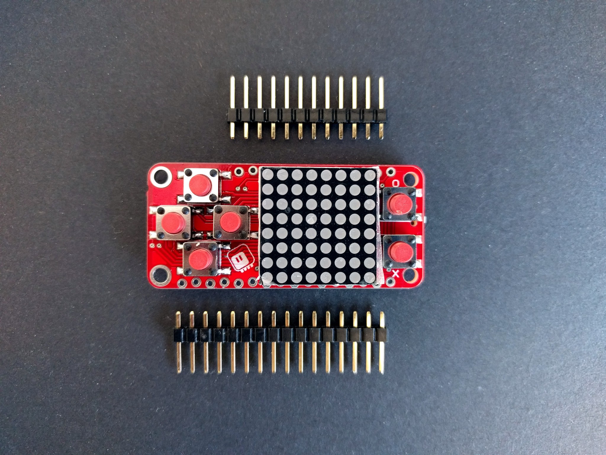
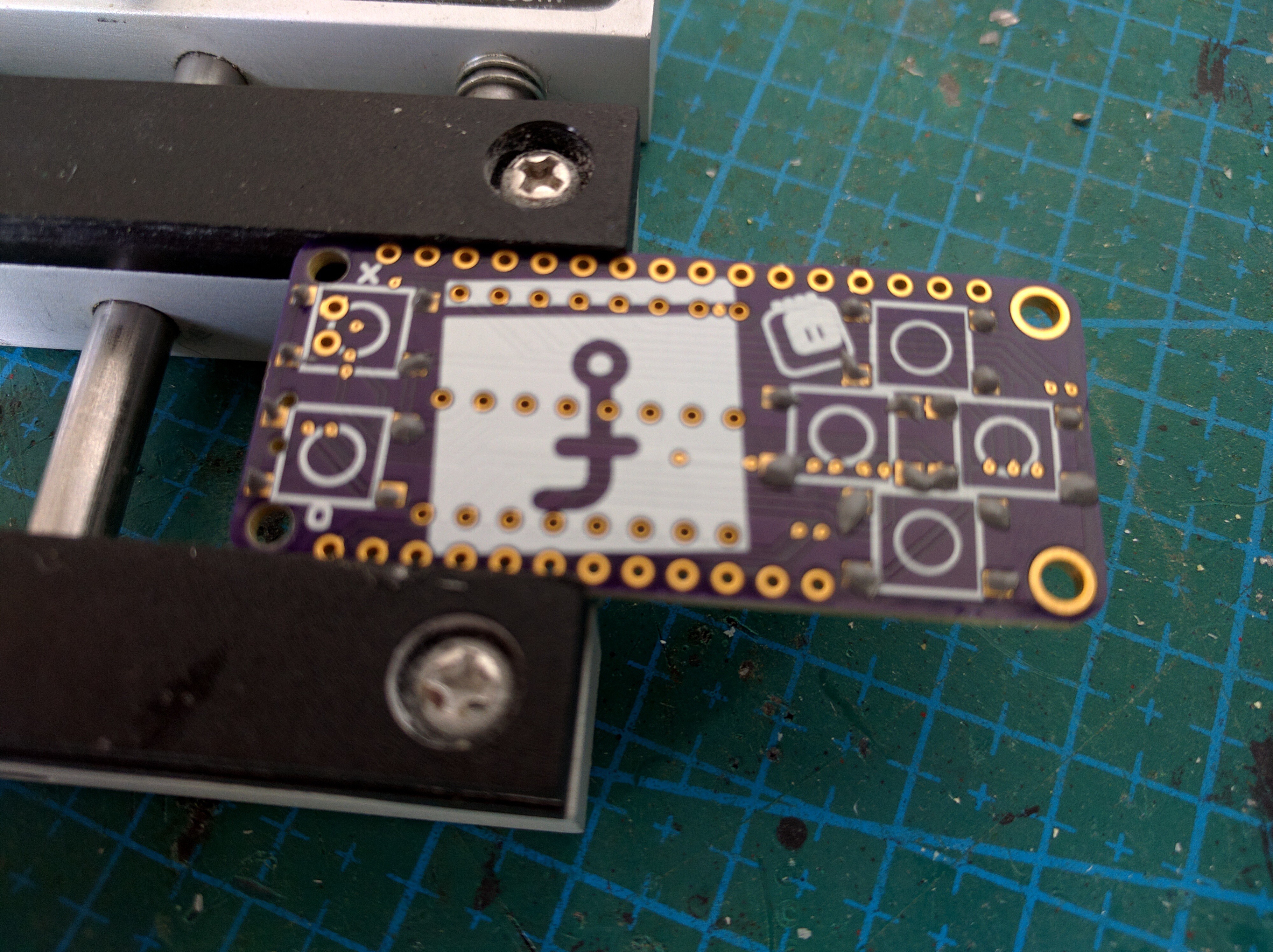
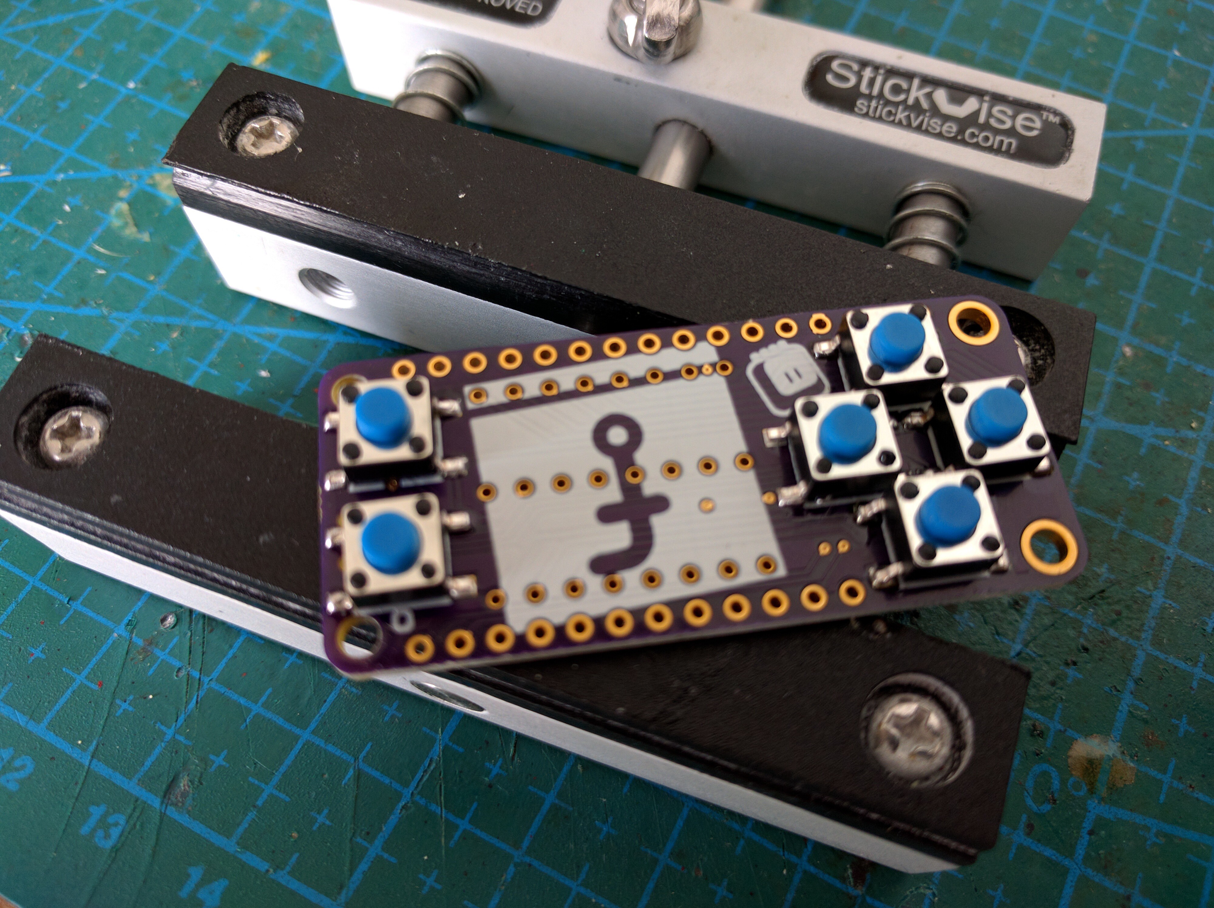
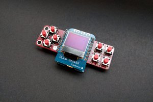
Did you customize your Feather board to have the female header row pointing to the top. My Feather came only with regular male pin headers?

  Are you sure? yes | no

deʃhipu wrote 07/16/2019 at 06:41 point

Sure, in fact, I usually use stacking headers. But you can as well just solder female headers to the featherwing.

  Are you sure? yes | no

Tom Carlson wrote 05/09/2018 at 14:33 point

I finally got around to playing with the one I bought off Tindie a while back. (So it's the prior version.) This is such a fun little gadget! It's just big enough to be usable.

Unfortunately, I must have screwed up my soldering somewhere because the red LEDs won't stay lit on the rightmost column. Red dots briefly turn red, then go to black. Orange dots turn green. And my crappy soldering skills resulted in the PewPew headers being stuck to the Feather so I can't pull them apart to check my work.

But all is good because that gave me an excuse to order a couple of the latest version!

  Are you sure? yes | no

deʃhipu wrote 07/15/2018 at 18:31 point

Hi, sorry I didn't see your message. The good news is that it's a software bug (off-by one) and that it has been fixed for a while, I just never got around to releasing the new version. If you get the new version of the library from GitHub releases page, you should have it fixed. Terribly sorry for that.

  Are you sure? yes | no

Tom Carlson wrote 07/16/2018 at 12:43 point

No problem! You answered back to my Tindie message right away and they're all working great now!

  Are you sure? yes | no

Orlando Hoilett wrote 08/06/2017 at 18:07 point

How comfortable does it feel when you're holding it? The Feathers are rather small.

  Are you sure? yes | no

deʃhipu wrote 08/06/2017 at 18:26 point

It's not the handheld heaven, but it's definitely better than some keychain games, such as the tamagotchi. The d-pad is pretty much the same size as on Nintendo DS Lite, the fire buttons are a bit closer (and I think they would feel better if they were farther apart, but there is simply no room).  The whole thing is wide enough to put the fingers of both of my hands on the back, which gives pretty comfortable and sure grasp. I suppose someone with hands bigger than mine could have problems, though.

What I am mostly struggling with is the thickness of the whole thing — when using standard headers it's almost 2cm together. This can be greatly improved by using the short pin headers, though, and there is still enough room between the boards to fit a battery.

  Are you sure? yes | no

oshpark wrote 05/10/2017 at 23:43 point

great project!

  Are you sure? yes | no

deʃhipu wrote 05/10/2017 at 23:46 point

Thank you, hopefully the new PCBs arrive before PyCon.US, so I can show them off there. They just got shipped, and if they arrive within 7 days, I'm good. Otherwise we will miss each other going opposite directions.

  Are you sure? yes | no

Similar Projects

Does this project spark your interest?

Become a member to follow this project and never miss any updates