 Tom Anderson
"Anyone who considers arithmetical methods of producing random digits is, of course, in a state of sin." - Von Neumann
This project provides an analog means to create true-random numbers from the thermal noise of resistors. The circuit is easy to measure and verify.
The recent unpleasantness in privacy rights and security from eavesdropping emphasizes the importance of secure cryptography. Hard crypto, the cypherpunks would call it. Random numbers are a necessary ingredient in the larger problem of cryptography.
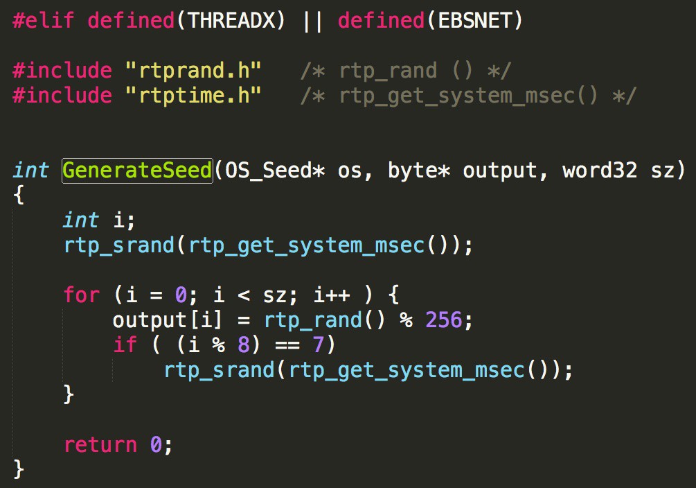
This project is somewhat similar to an existing product, the TrueRNG – Hardware Random Number Generator, which used to be available as a $50 USB stick. I don't think there is really much of a market for this type of device. The benefit from this design will come from it being incorporated into other products to make them more secure. For example, IoT devices should be running HTTPS, and yet they may not have a ready source of entropy from their random number generator. These numbers are (slowly) generated by the Linux Kernel and put into a 4k buffer. Sources of entropy in Linux for these devices is mostly limited to network traffic. This is not always a great way to do this, and is not done in all cases. Here example random number generators used to seed SSL from the CyaSSL library. It has #ifdefs for the various operating systems, since they vary with the available hardware:
Not good. Sinful, actually. Not as bad as this one, though:
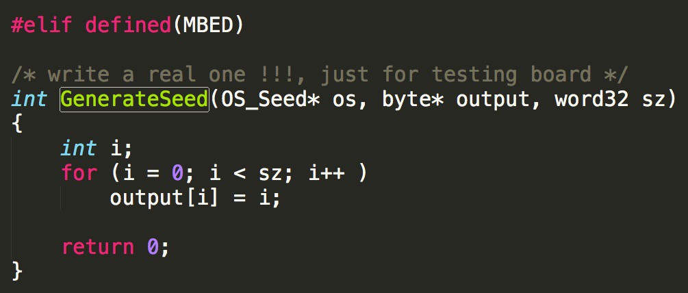
Some processors have built-in random number generators that might be pretty good. Who knows? They can't be verified by the application designer.
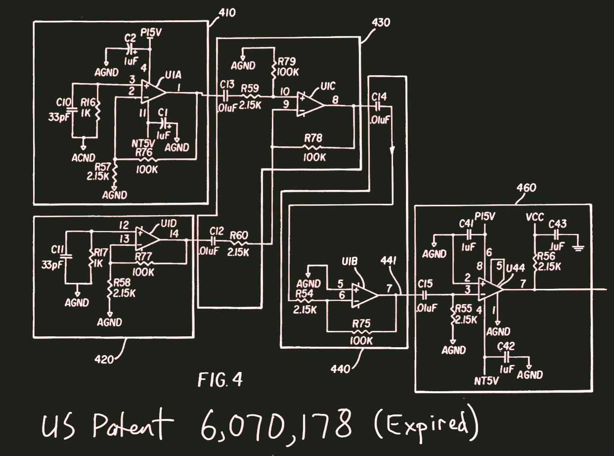
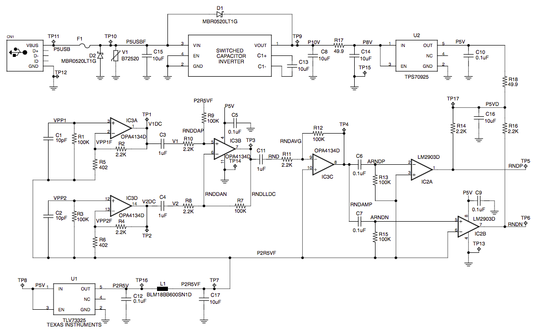
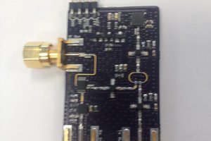
I designed this random number generator where the source of randomness is the thermal noise in a resistor:
My original prototype was hand-soldered to a 68HC11 board that had a prototyping area, using components from a local surplus store. I don't know where the board is now, but I might be able to find it and post a picture. I wrote code to send the random bits out the RS-232 port, which I connected to an HP-735 workstation. I wrote test code for verifying that the output data is random. These days, there is more code available for that purpose.
The patent was assigned to a startup, who embedded it into a crypto product. The startup dissolved and they did not pay the renewal fee. This irrevocably ended their rights to it, and the circuit can be freely copied. This will take care of the analog section of generating the numbers. For this project, I am going to have to create a new digital interface, since apparently the 68HC11 is no longer in vogue. I checked, and there are a few parts left on Digi-Key! But I have thrown out my paper copy of the Pink Book.
I got a discount offer from AutoDesk for the Standard Version of EAGLE, and paid $50 for a 1 year subscription. The offer was because I have a free account on circuits.io. I like the EAGLE XML file formats for schematic and layout, so I had wanted it anyway. I took an EAGLE class last year from Matt Berggren, and today I watched some refreshers on YouTube (part1) (part2) (part3) by Jeremy Blum. If I don't like EAGLE, I'll probably try KiCAD again. If anyone wants to help with the project and has strong feelings about which tools to use, I am open to suggestions.
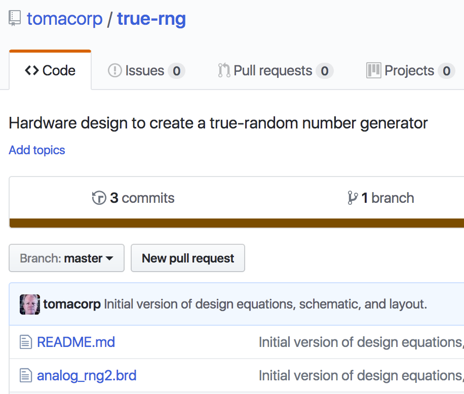
I created a project github repo. The EAGLE files are there under revision control, along with any firmware and application software. The name of the repo is true-rng. The license is BSD.
When talking with people about the circuit online and at meetups, there are some common questions:
What is new about it?
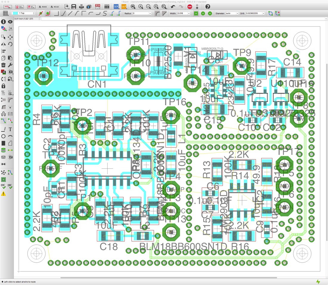
I have recalculated the design, with all new the signal levels and bandwidth. I used modern surface-mount components, and created a new layout. There was no existing open version of this design to start from.
The first big change was to the power supply. I have made non-trivial changes: The old design required a positive and a negative supply, and the new design uses a single supply. Creating a low-noise design with a single supply is a challenge. The...
Read more »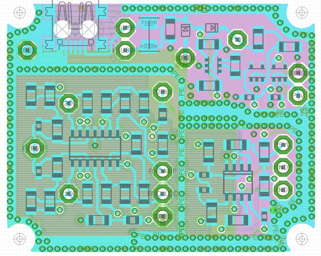


 John Wetzel
 Lucy Fauth
Numerology can change your perspective on life and your objectives and aims by drawing you towards a different pathway myinnerhustle. Through numerology, you can determine personality traits, the future, and facts about relationships, which collectively will change your life. In my opinion, all this greatly depends on faith because if you’re not a true believer, nothing will change.