 Pavel
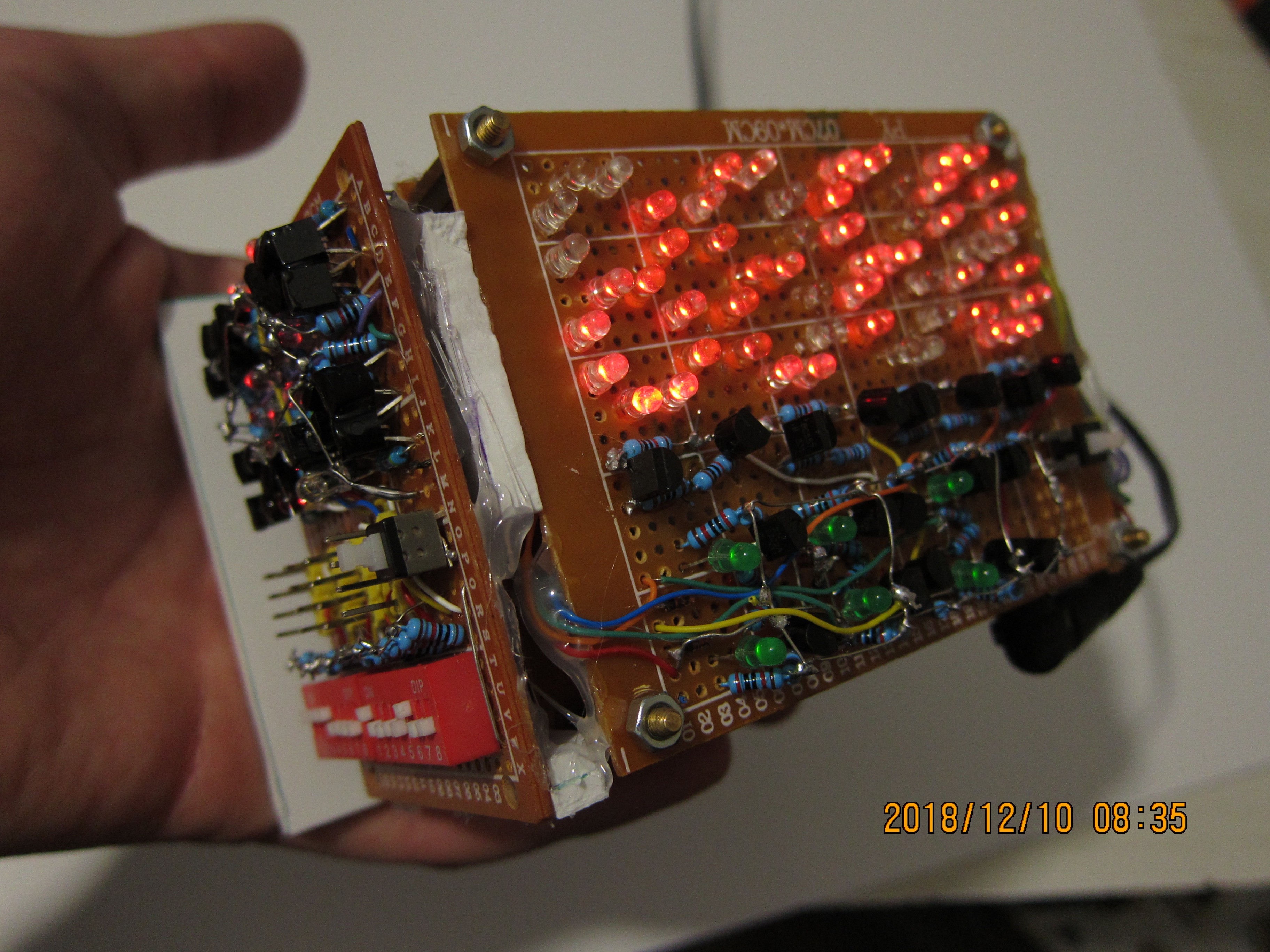
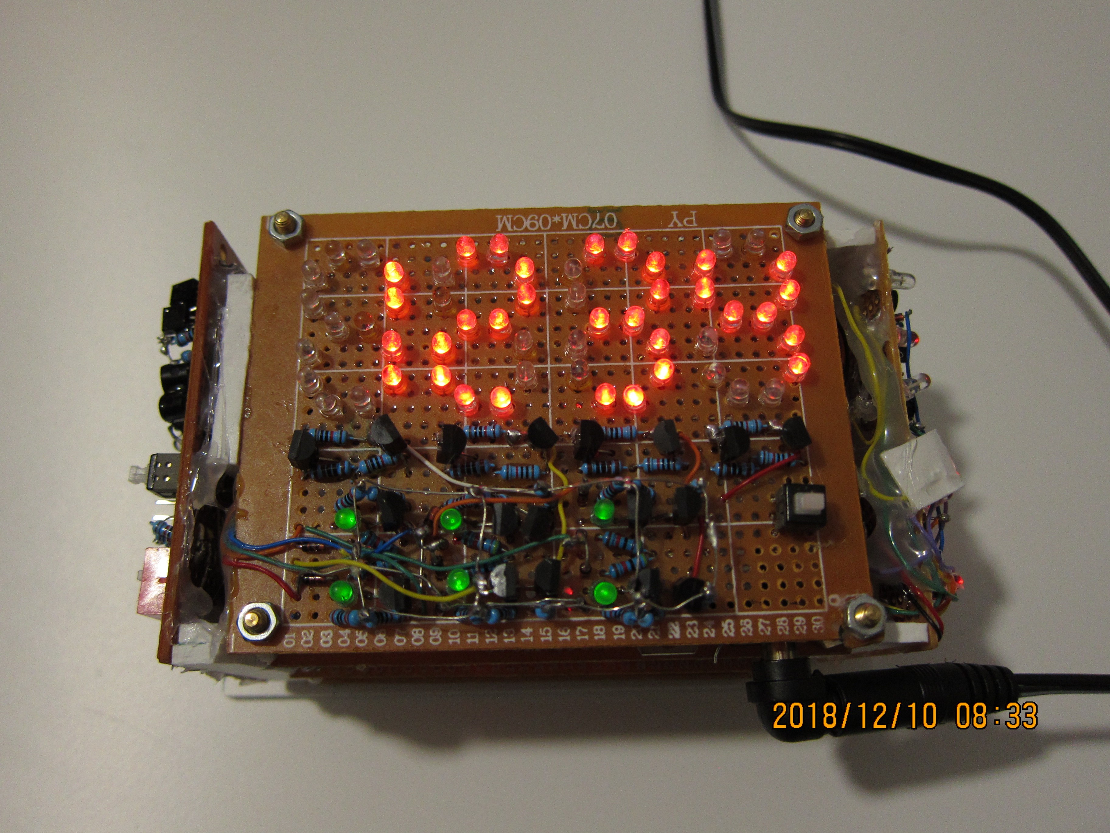
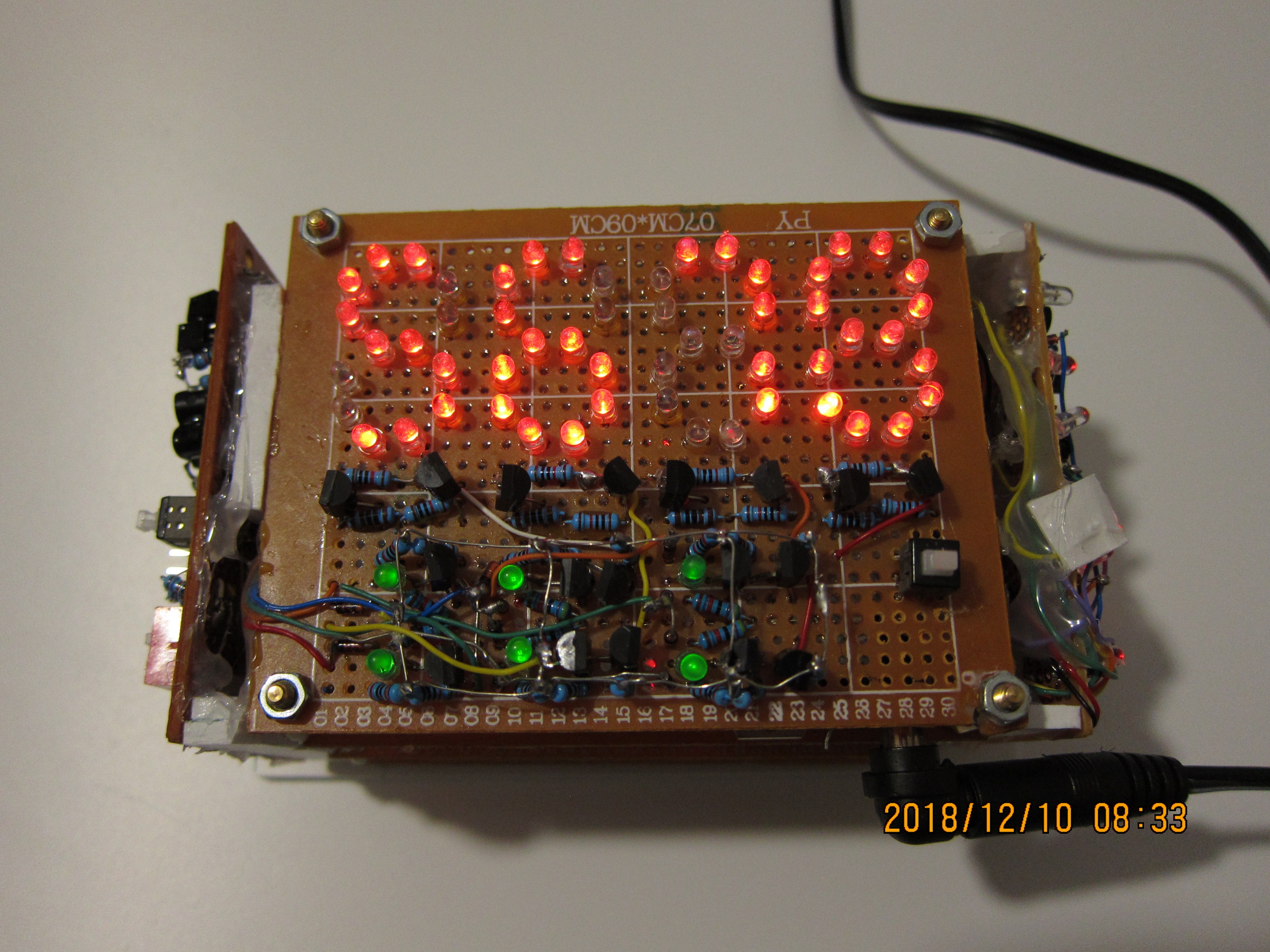
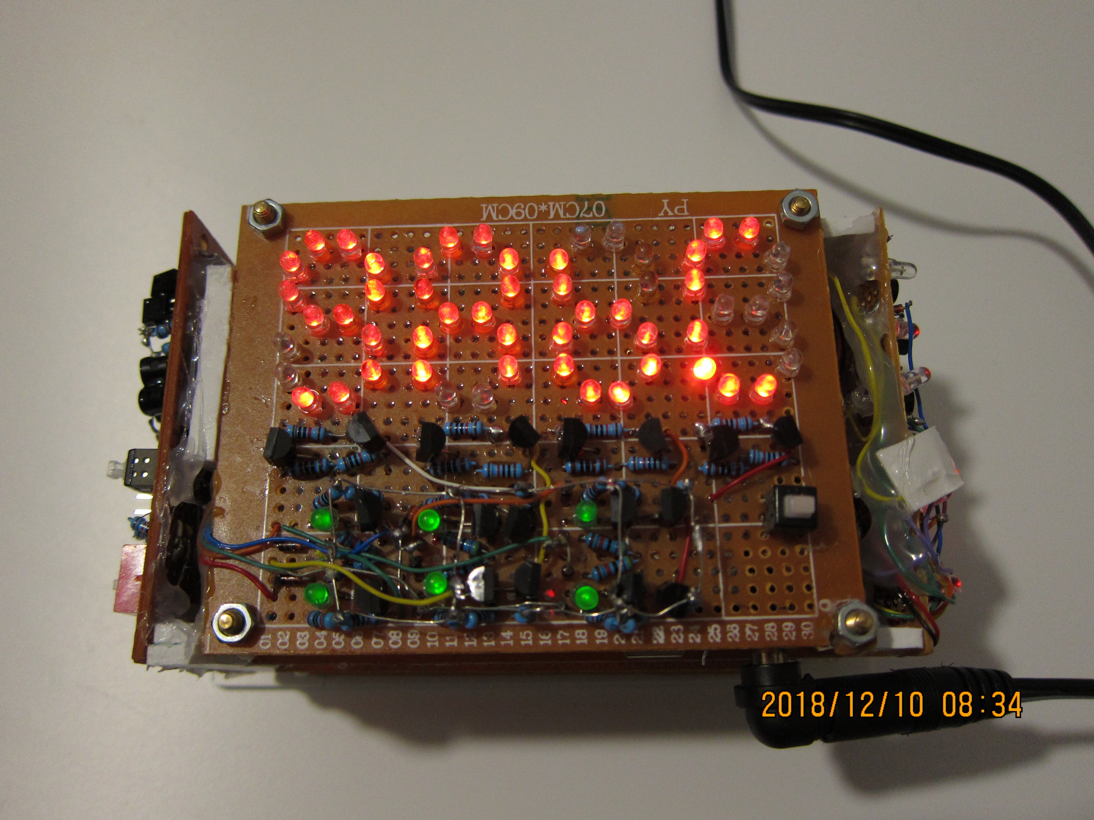
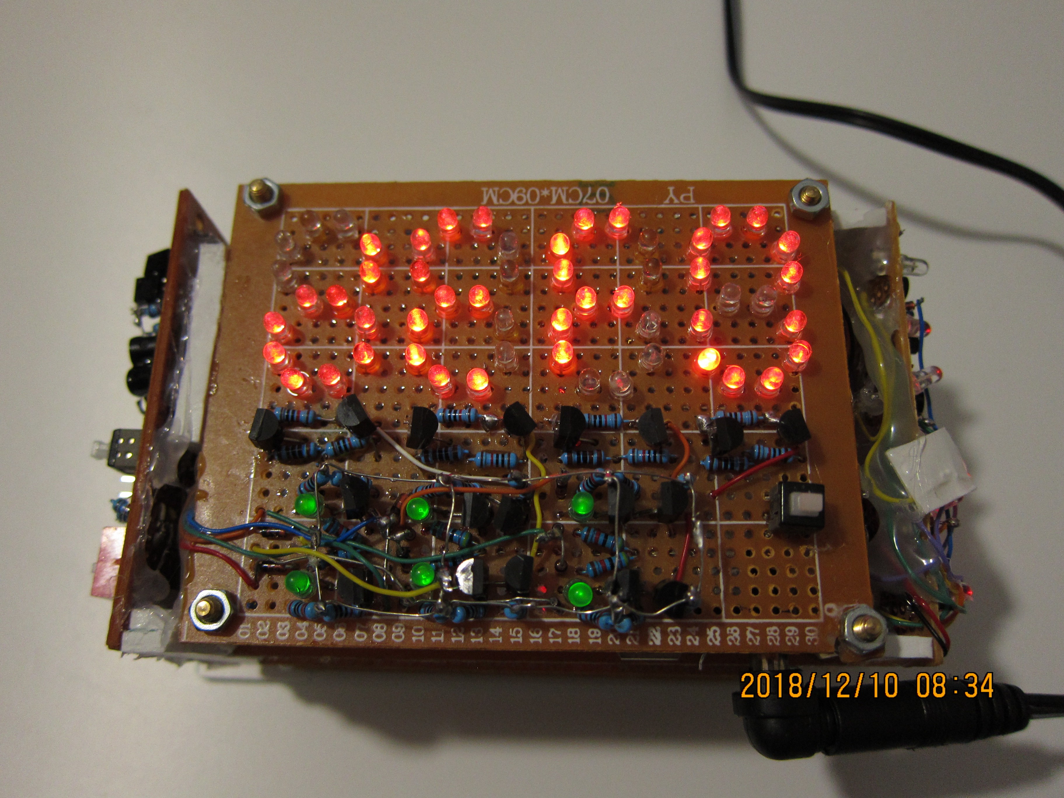
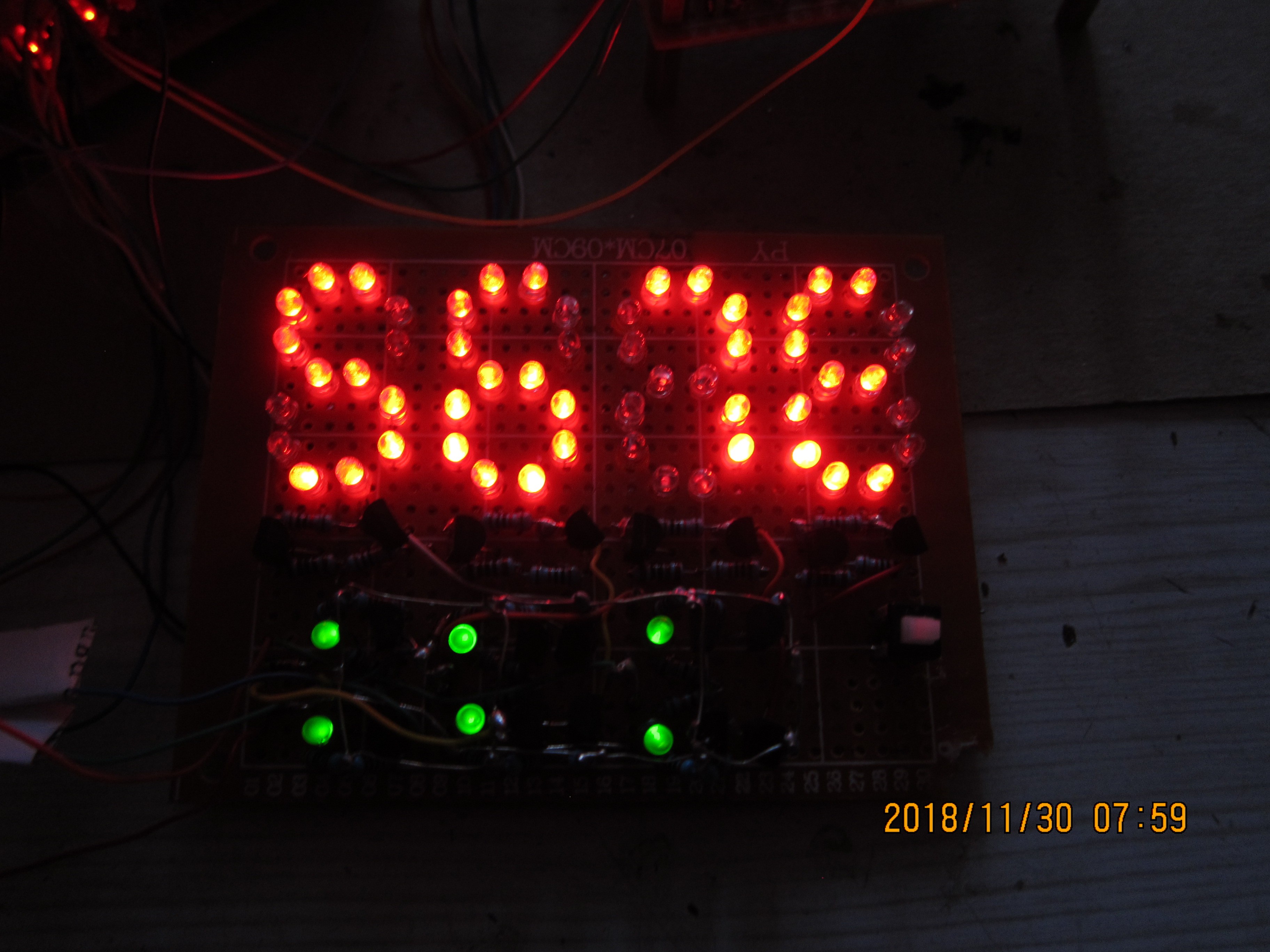
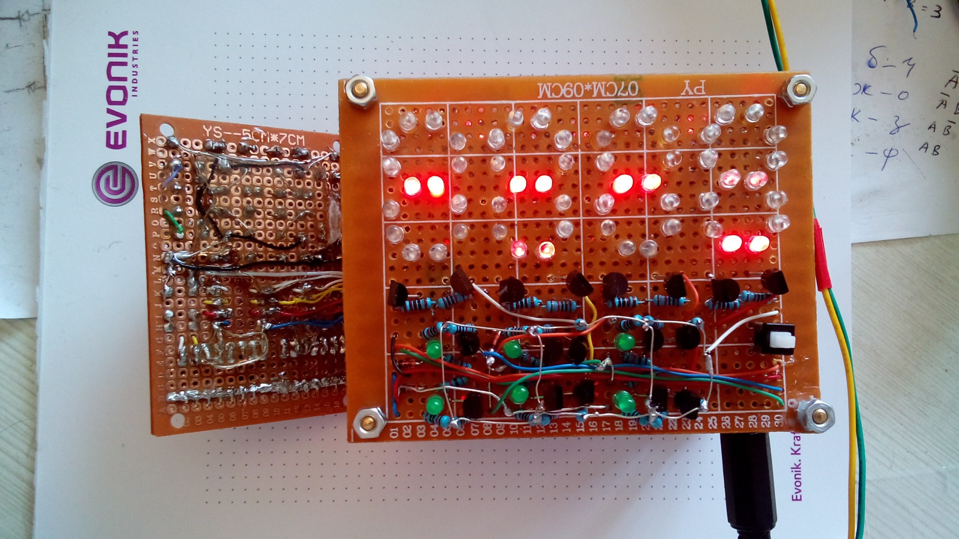
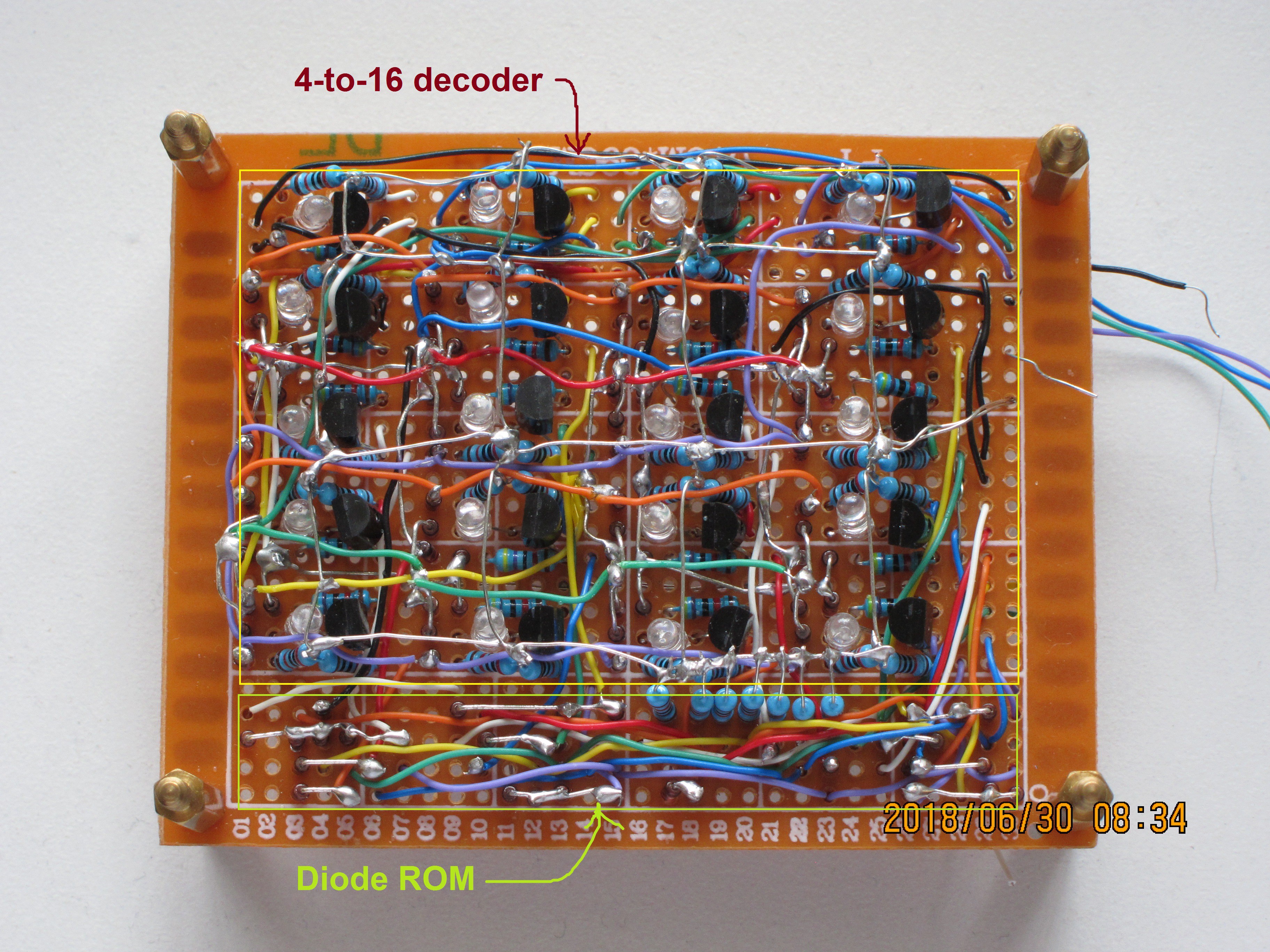
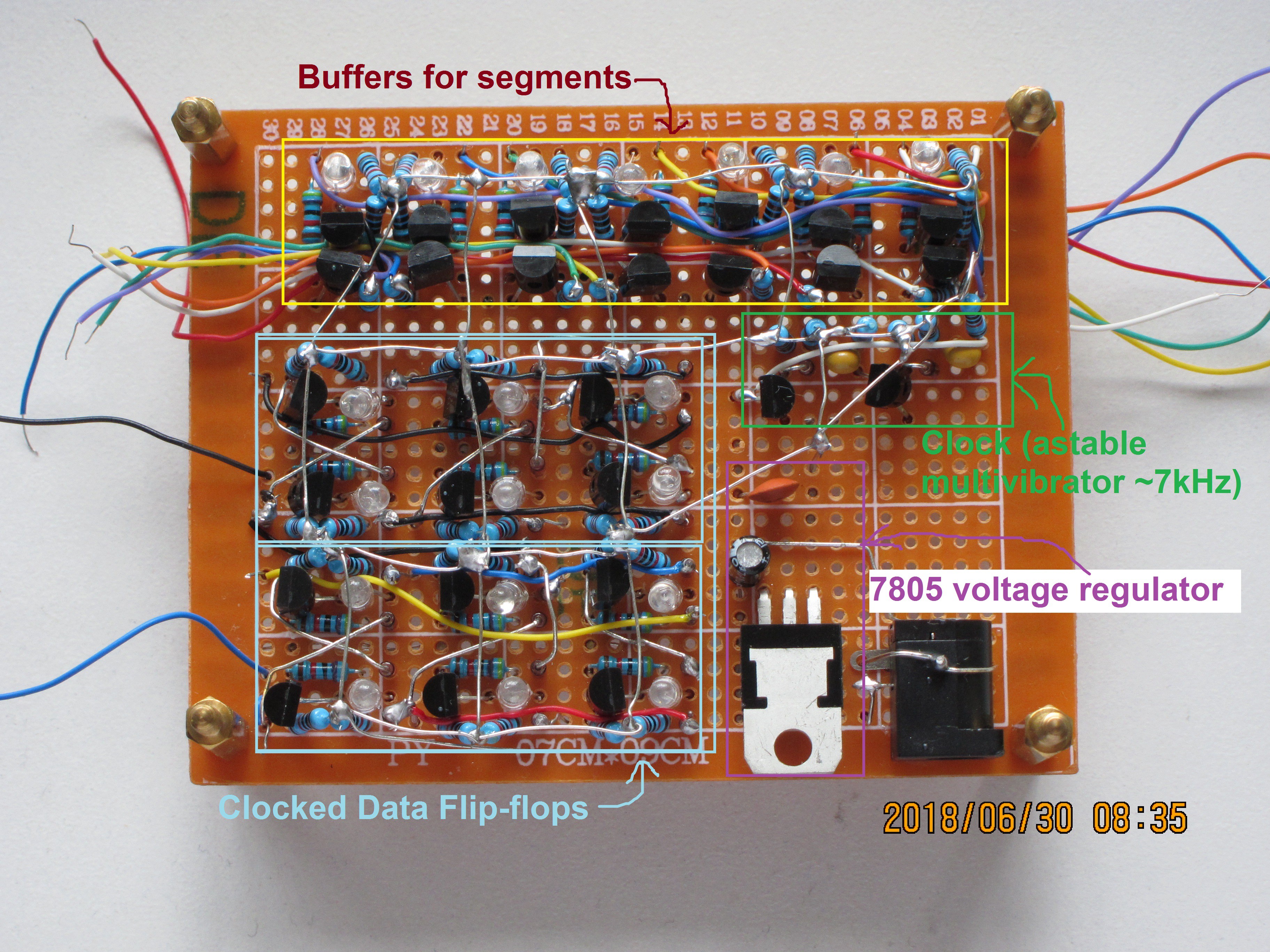
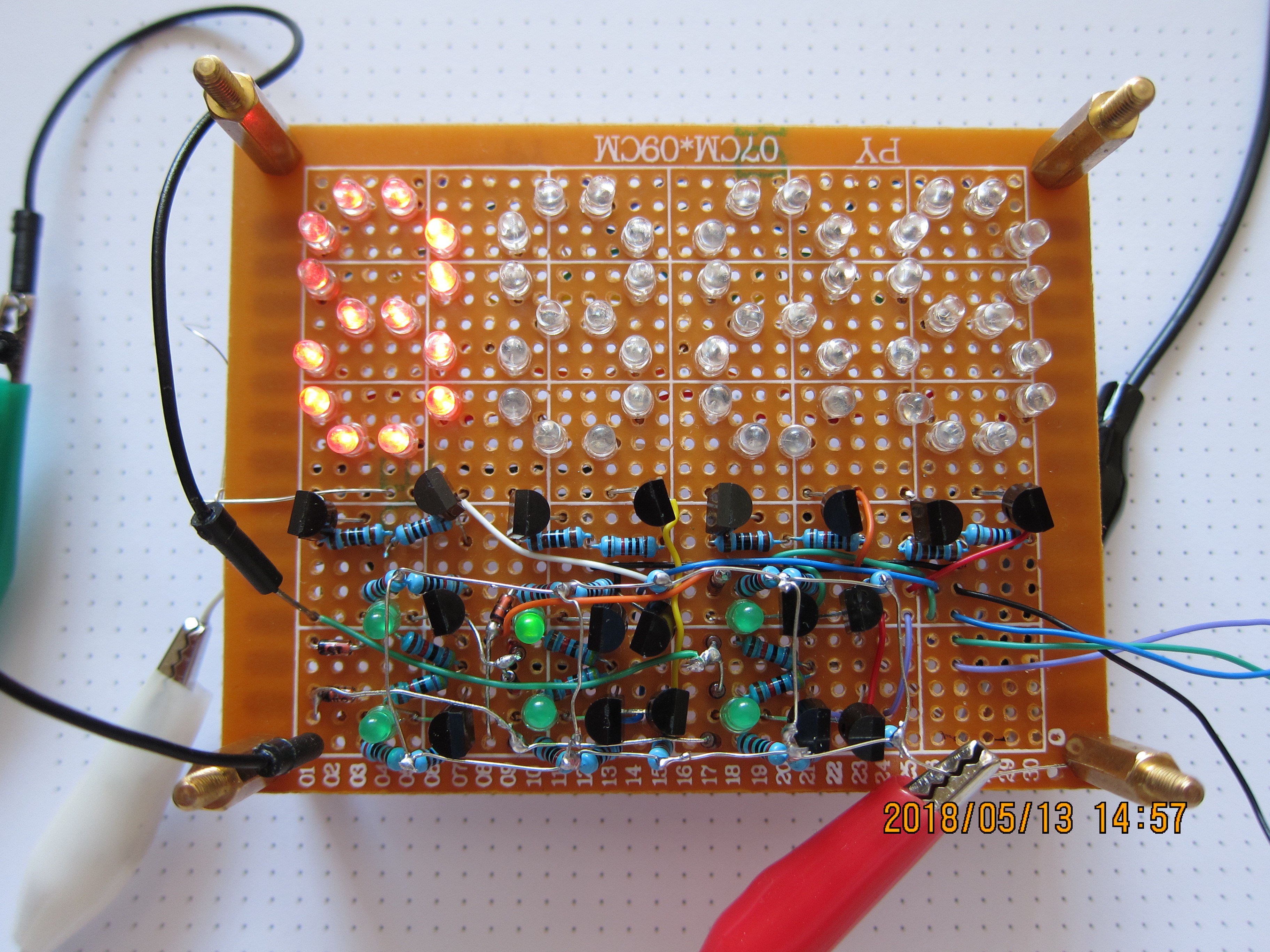
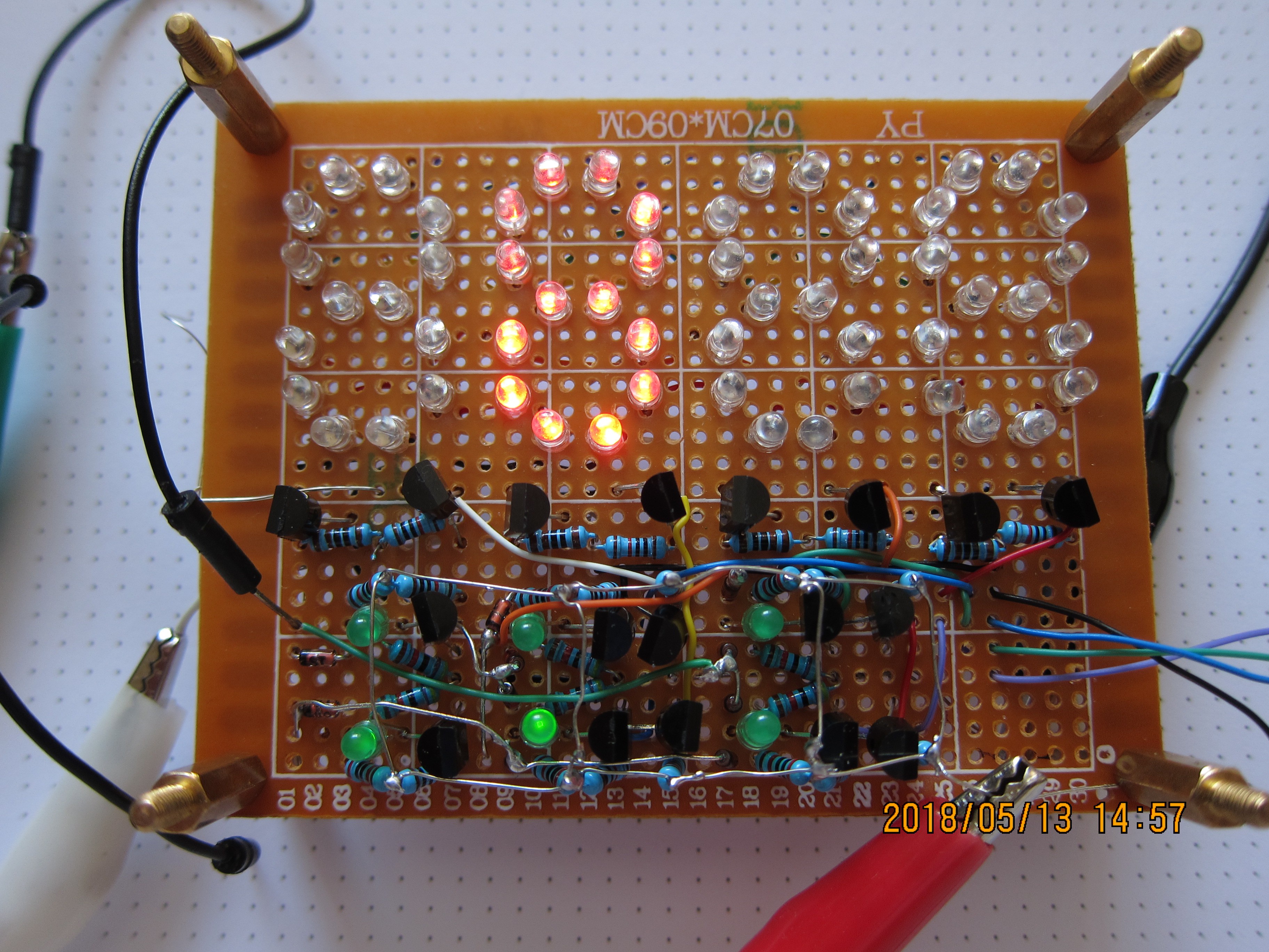
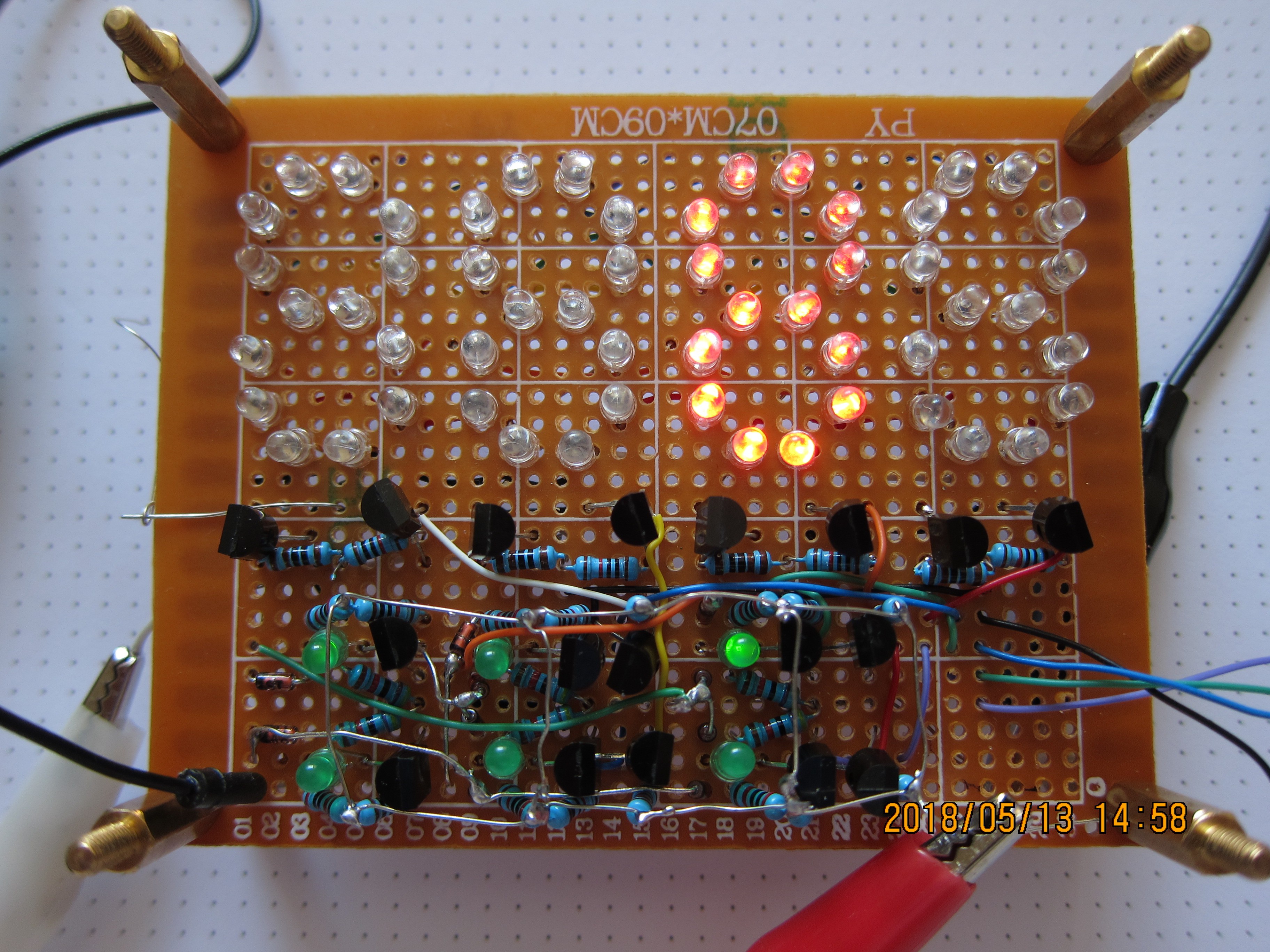
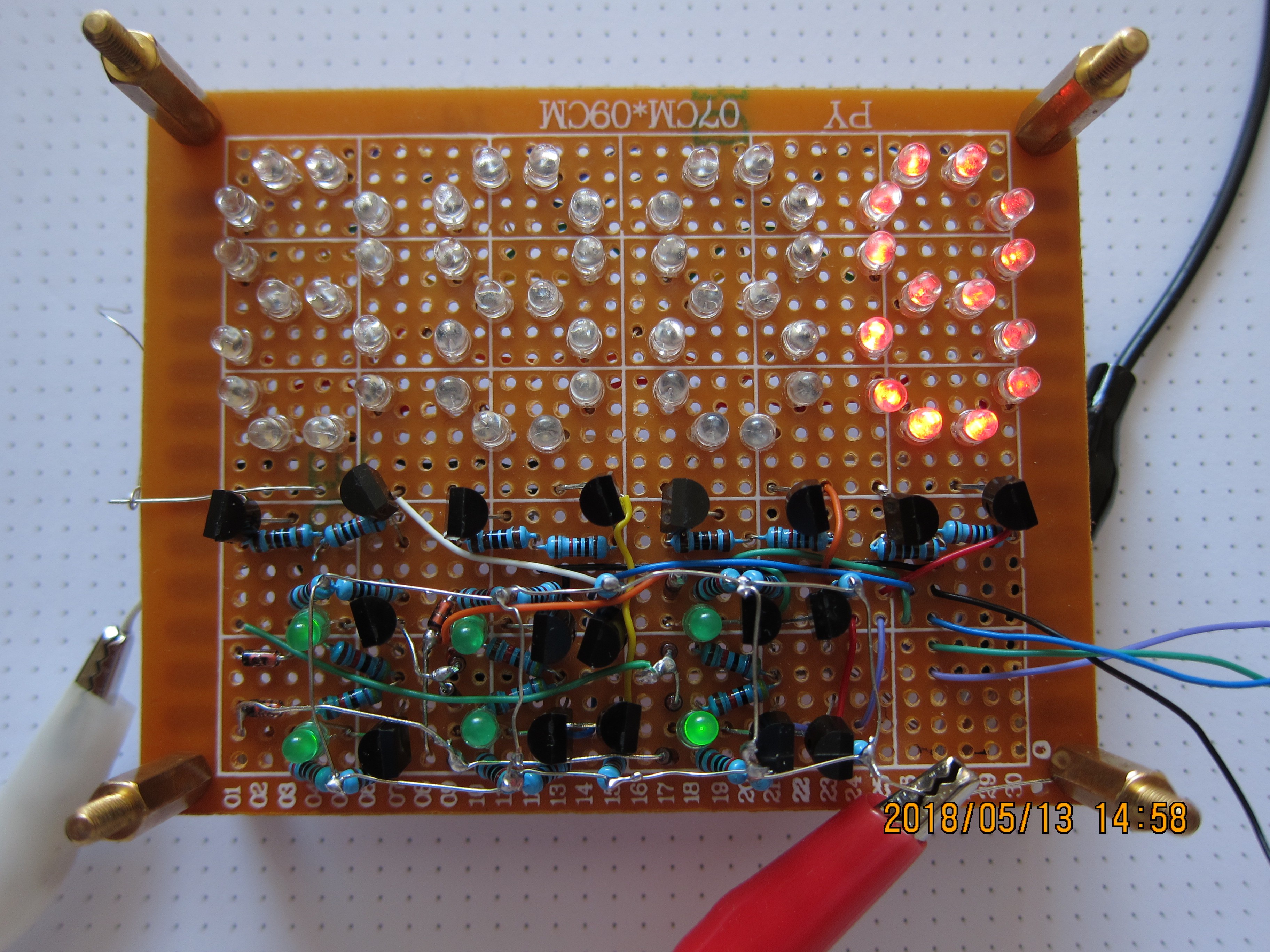
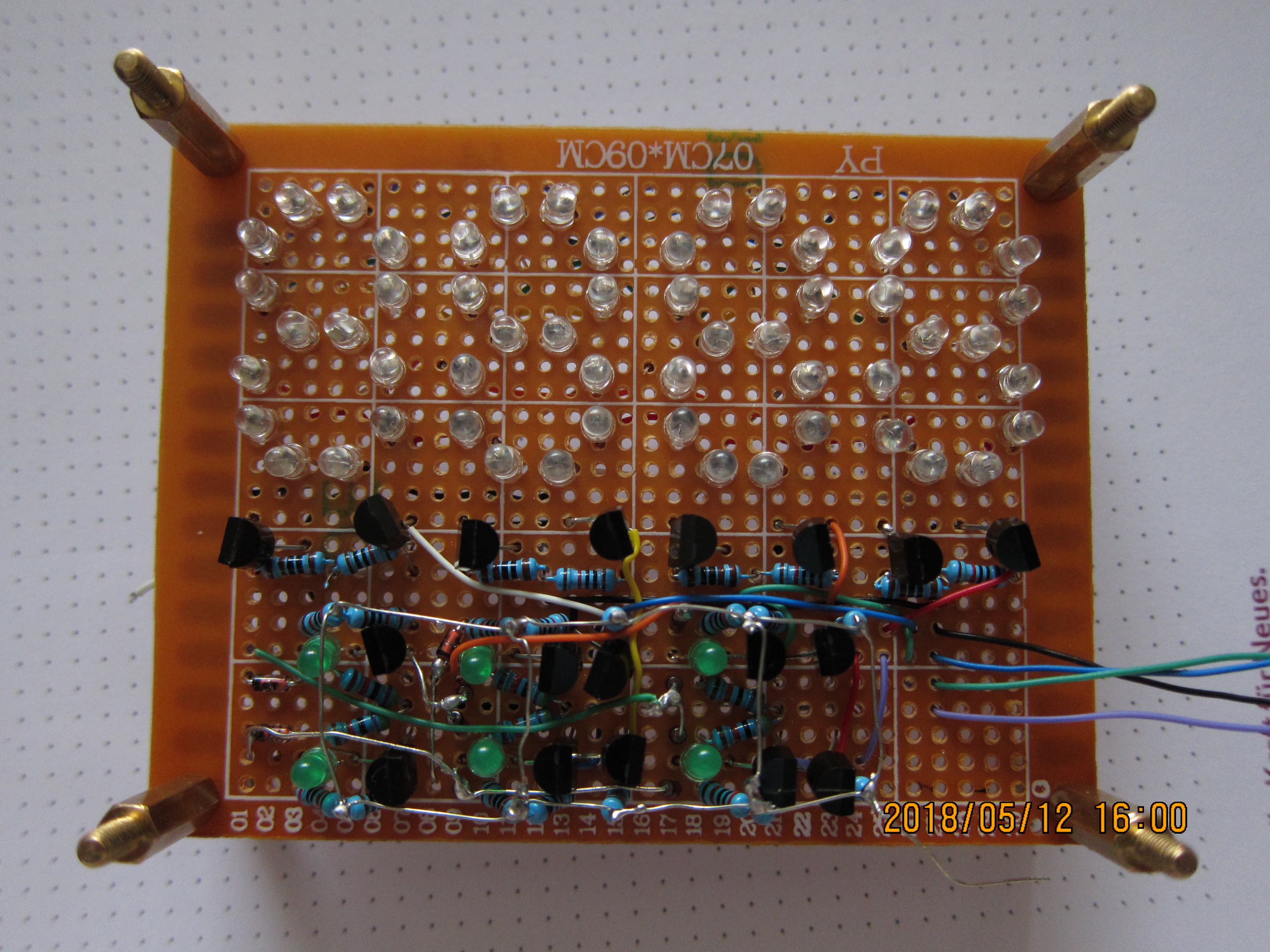
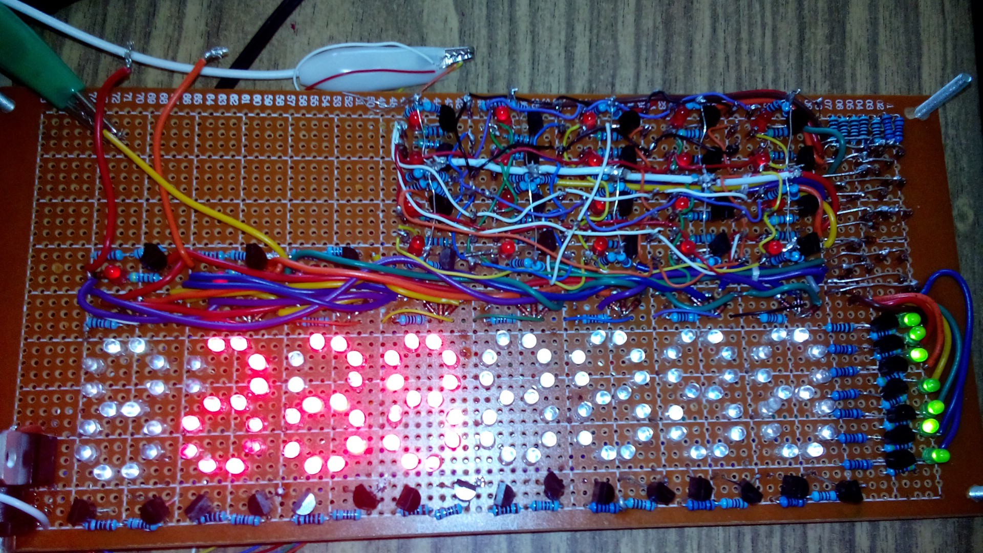
PavelThe aim of this project is to build a display unit, which can display characters (hex digits) when given a binary input. Built only with discrete transistors, LEds, etc. it will work through multiplexing, showing each 7-segment character one by one, in quick succession, so it will seem to eye as if it displays all characters simultaneously.
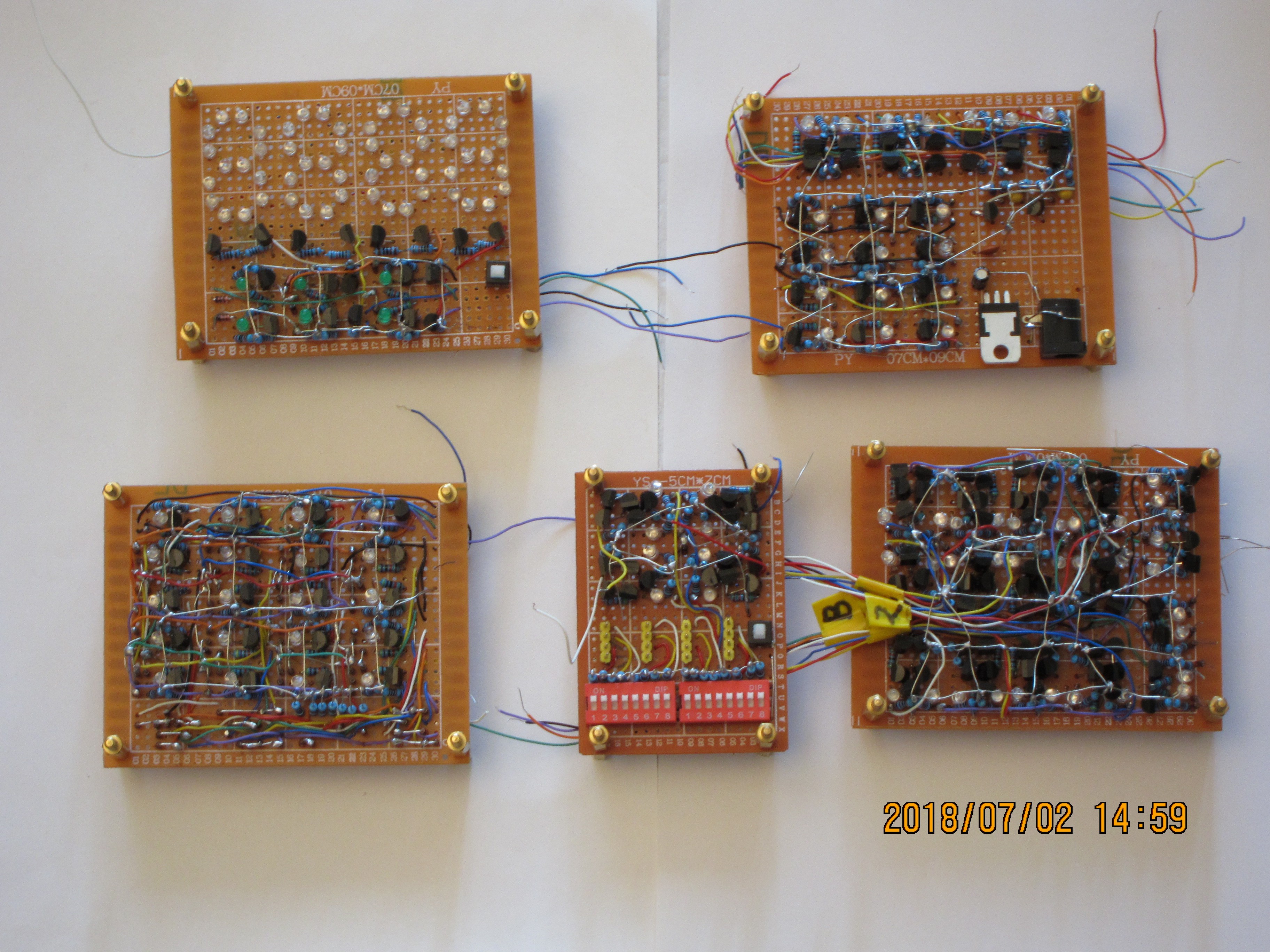
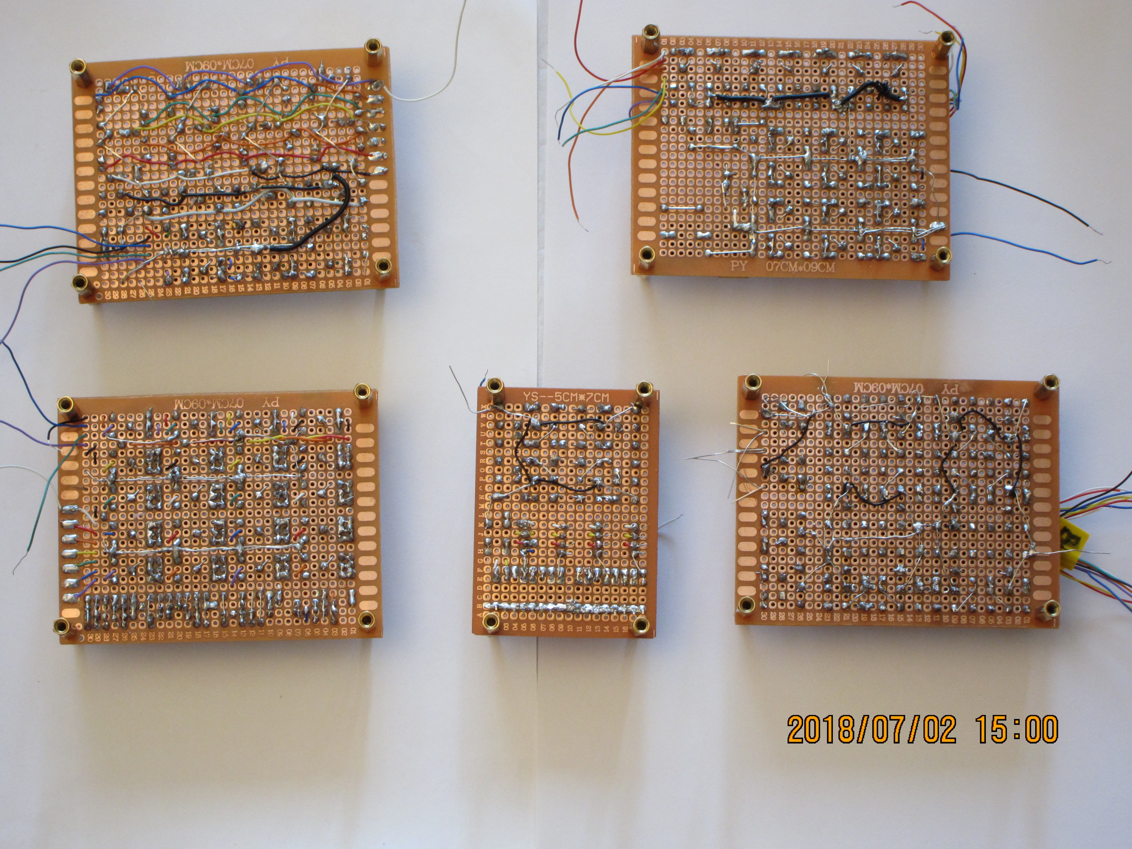
First iteration was building 8 character display, but it was a fail (due to its great size, complexity and mismatch of different modules, as well as flexibility of big board which resulted in breaks of several connections). I think now, it was too ambitious.
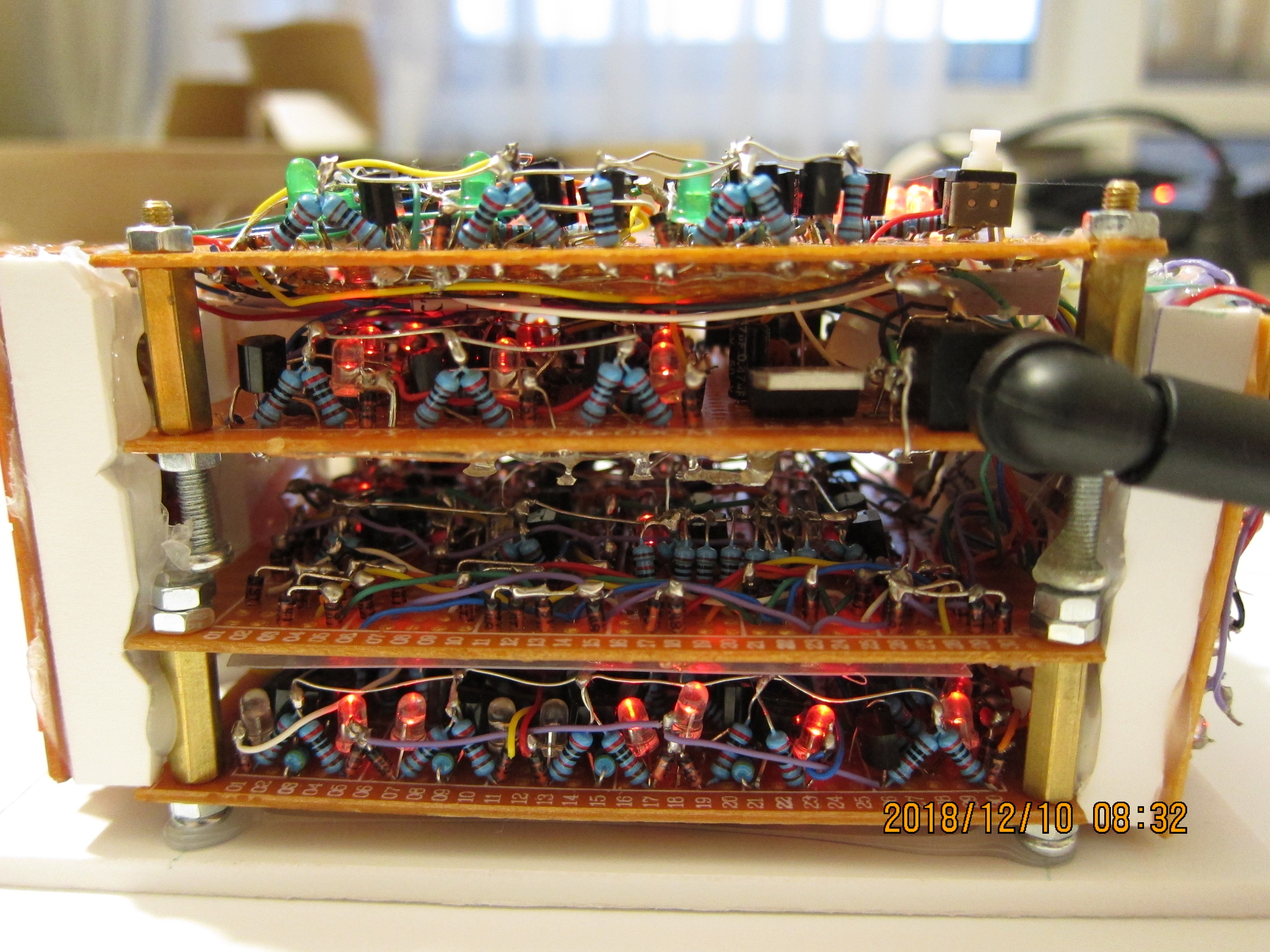
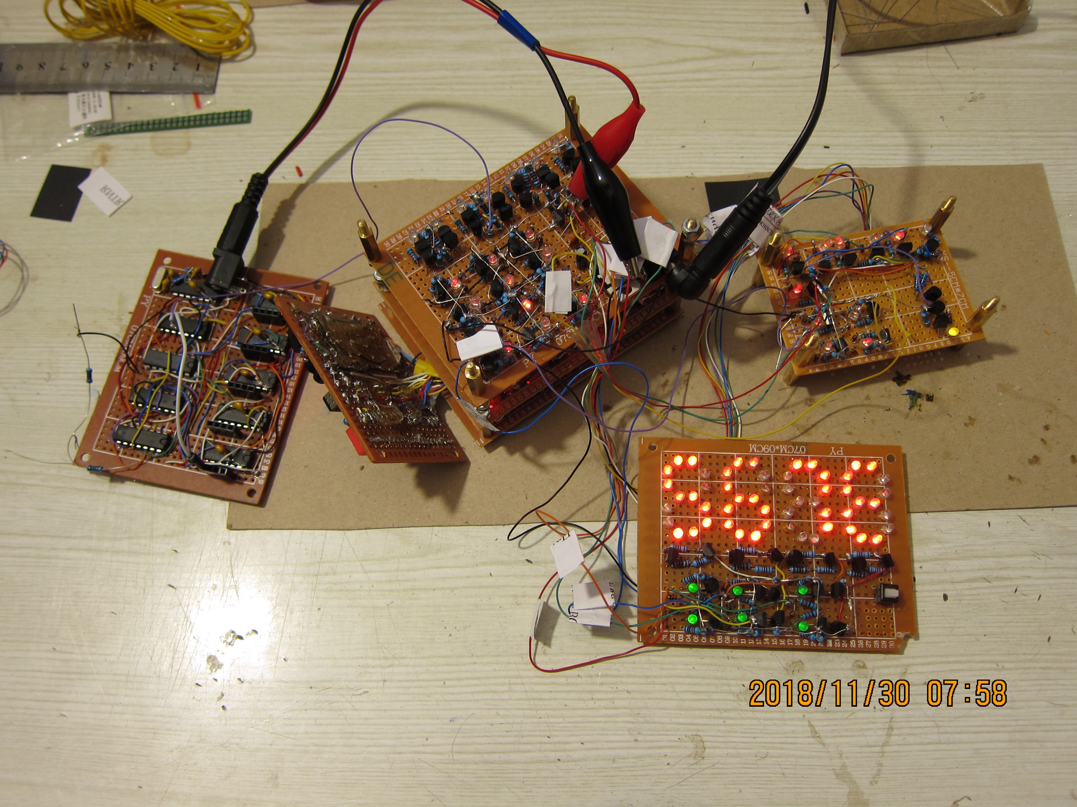
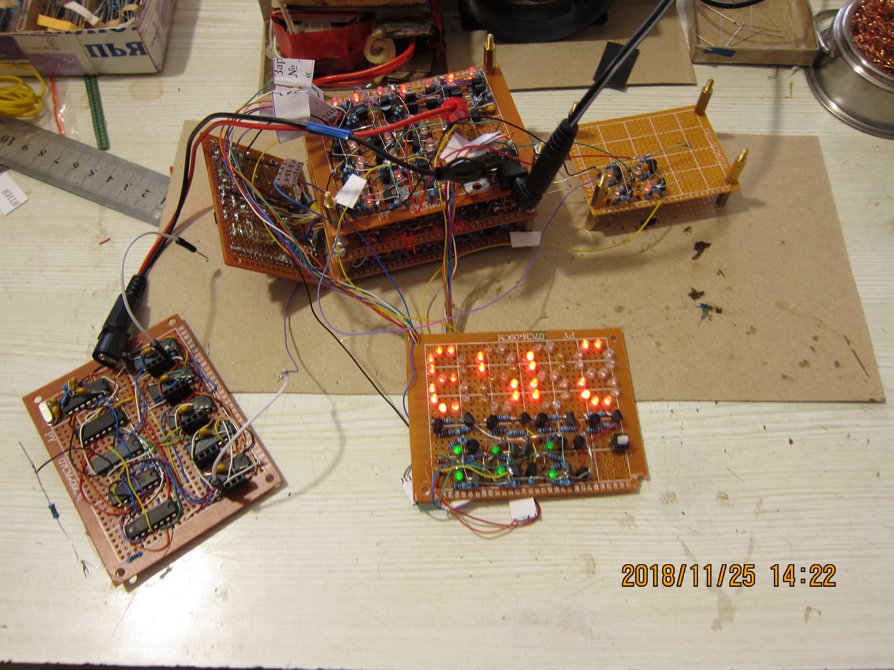
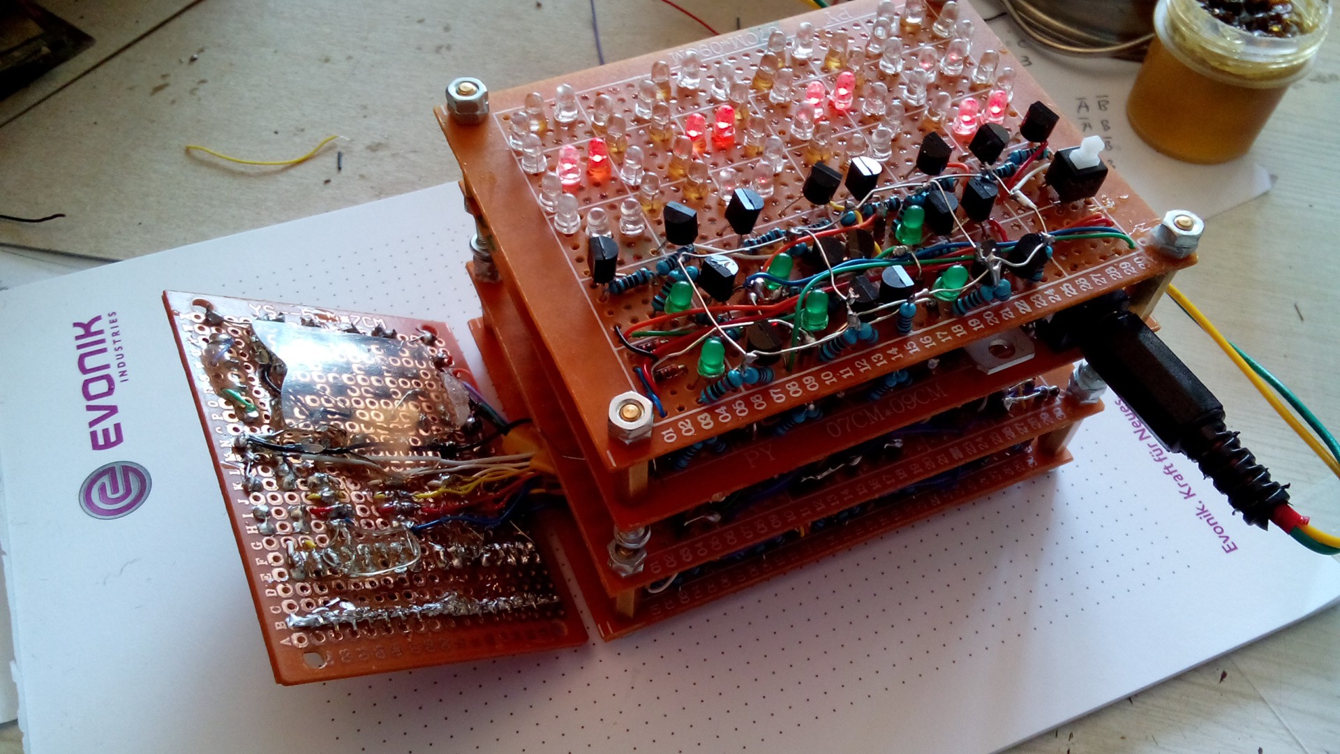
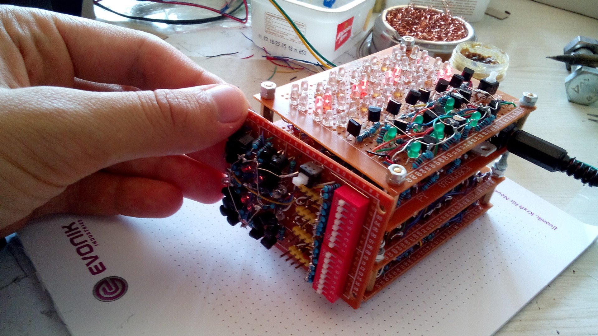
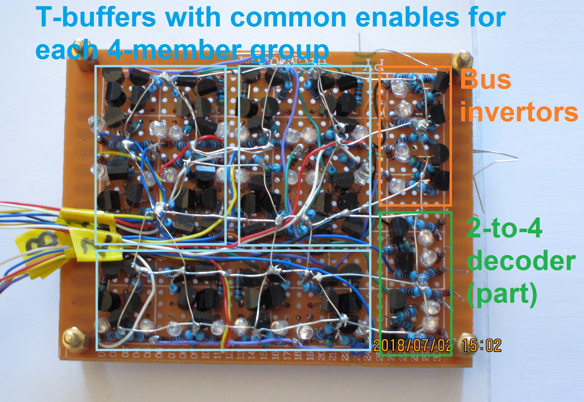
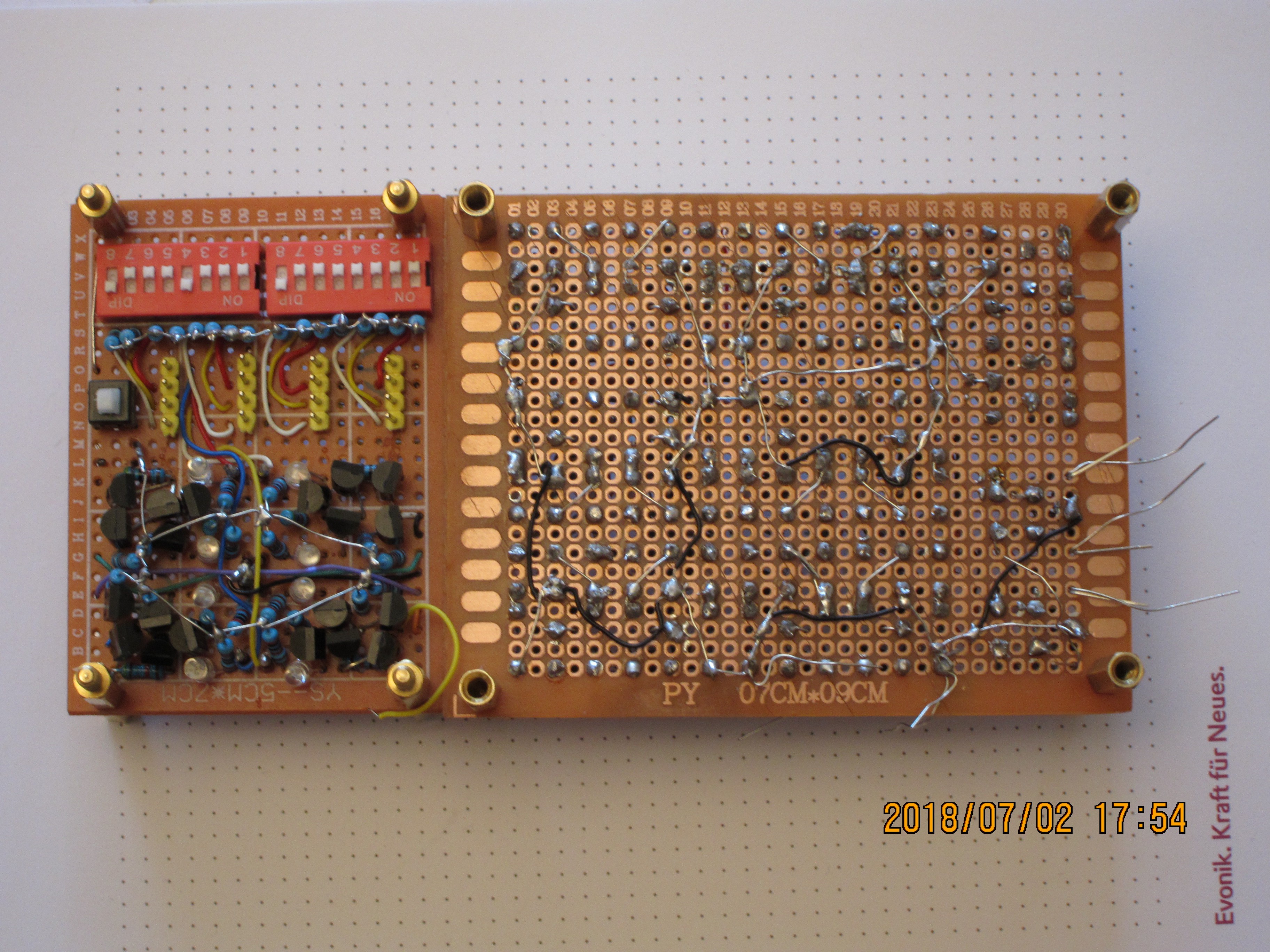
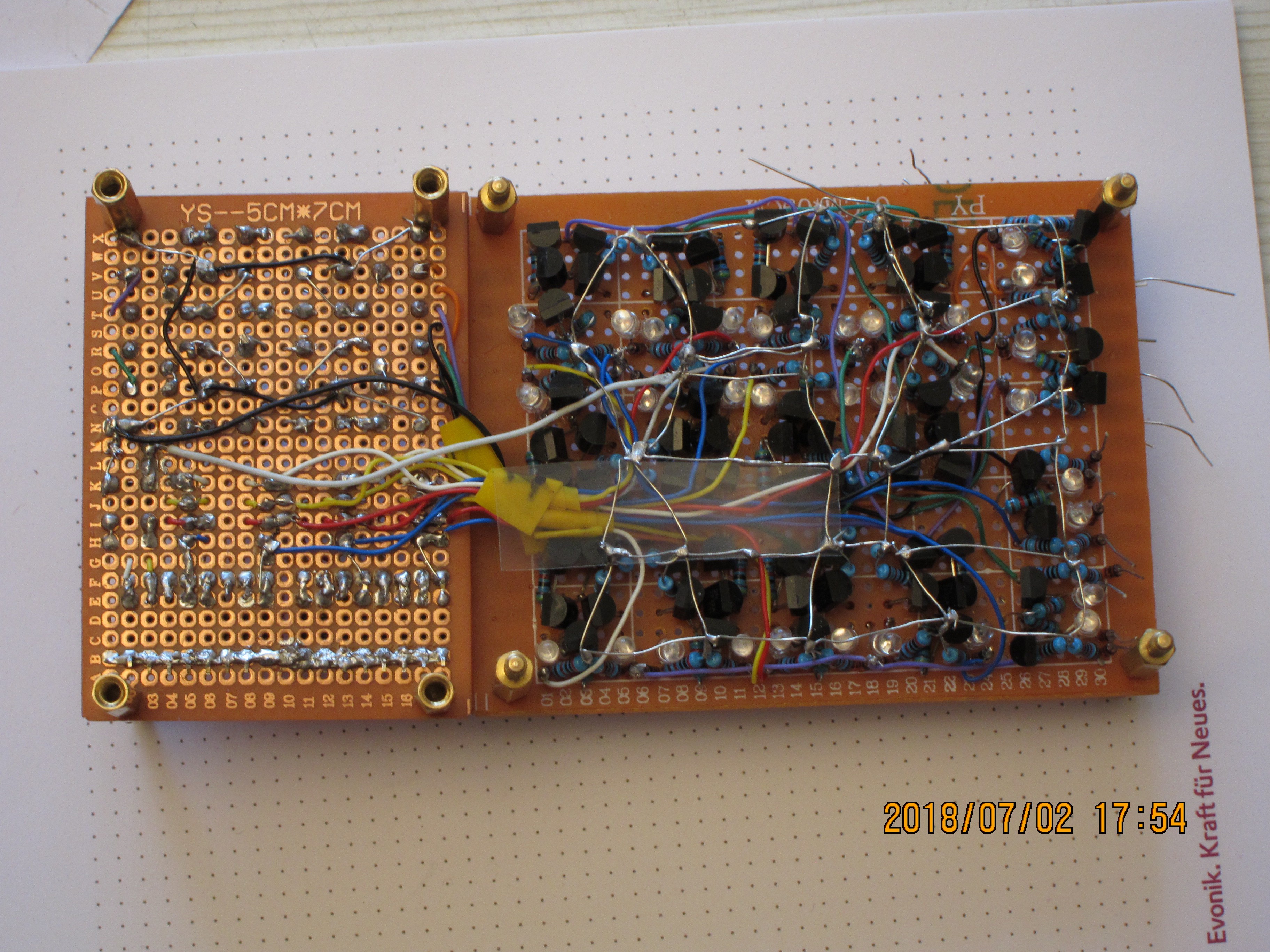
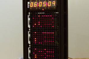
Current iteration is 4 characters, made of several smaller and more rugged boards, and this made it possible to become functional.


 Ted Yapo
 Bharbour
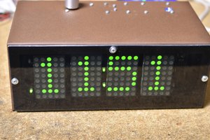
 Ken Yap
Good job, thats what hacking is all about :-D