 Andrey Skvortsov
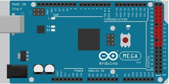
Used arduino pins scheme.
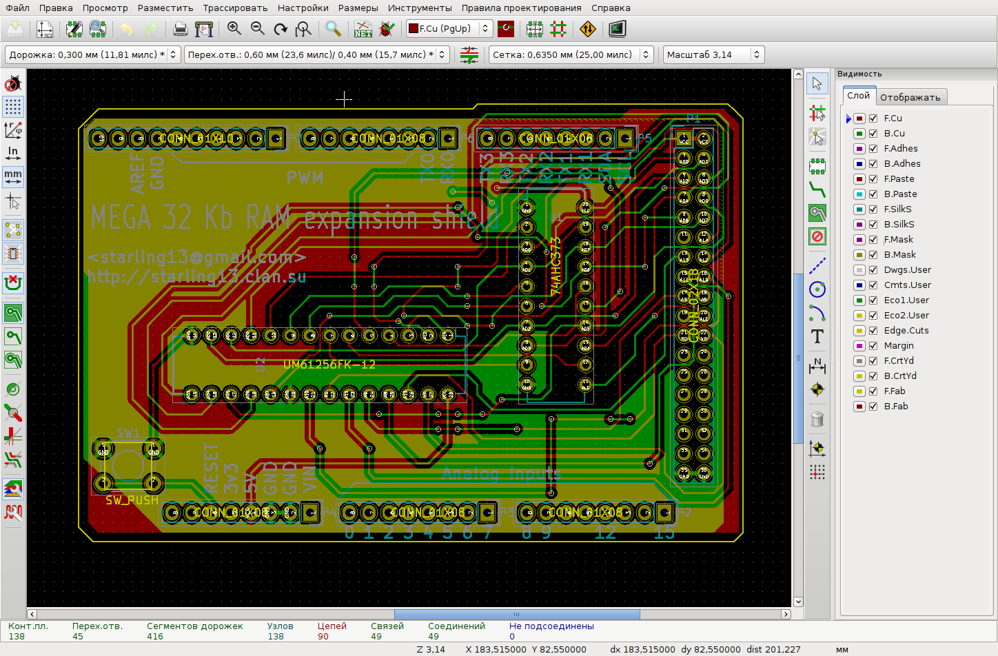
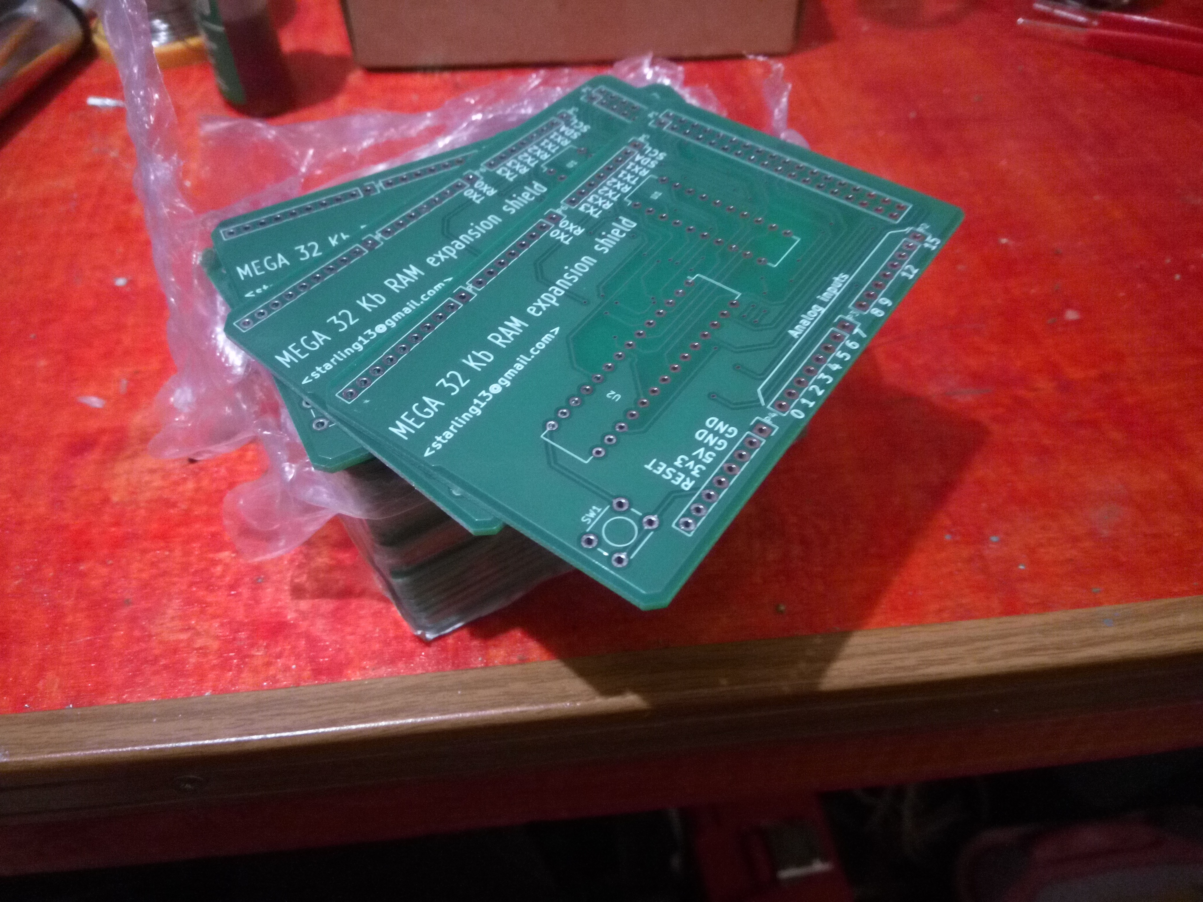
KiCad sceenshot with current result.
Arduino IDE sketch for testing the shield on different wait states
/*
 * This is free and unencumbered software released into the public domain.
 *
 * Anyone is free to copy, modify, publish, use, compile, sell, or
 * distribute this software, either in source code form or as a compiled
 * binary, for any purpose, commercial or non-commercial, and by any
 * means.
 *
 * In jurisdictions that recognize copyright laws, the author or authors
 * of this software dedicate any and all copyright interest in the
 * software to the public domain. We make this dedication for the benefit
 * of the public at large and to the detriment of our heirs and
 * successors. We intend this dedication to be an overt act of
 * relinquishment in perpetuity of all present and future rights to this
 * software under copyright law.
 *
 * THE SOFTWARE IS PROVIDED "AS IS", WITHOUT WARRANTY OF ANY KIND,
 * EXPRESS OR IMPLIED, INCLUDING BUT NOT LIMITED TO THE WARRANTIES OF
 * MERCHANTABILITY, FITNESS FOR A PARTICULAR PURPOSE AND NONINFRINGEMENT.
 * IN NO EVENT SHALL THE AUTHORS BE LIABLE FOR ANY CLAIM, DAMAGES OR
 * OTHER LIABILITY, WHETHER IN AN ACTION OF CONTRACT, TORT OR OTHERWISE,
 * ARISING FROM, OUT OF OR IN CONNECTION WITH THE SOFTWARE OR THE USE OR
 * OTHER DEALINGS IN THE SOFTWARE.
 *
 * For more information, please refer to
 */

static void testOk() {
  digitalWrite(LED_BUILTIN, HIGH);
  delay(500);
  digitalWrite(LED_BUILTIN, LOW);
  delay(500);
}

static void testFail() {
  for (uint8_t i=0; i<3; ++i) {
    digitalWrite(LED_BUILTIN, HIGH);
    delay(50);
    digitalWrite(LED_BUILTIN, LOW);
    delay(50);
  }
}

void log(const char *str) {
  div_t d = div(millis(), 1000);
  Serial.print(d.quot), Serial.write('.'), Serial.print(d.rem);
  Serial.print(" >>> ");
  Serial.println(str);
}

static volatile uint8_t *extmem = reinterpret_cast<volatile uint8_t*>(0x8000);

bool test() {
  for (uint16_t i = 0; i<32768; ++i) {
    extmem[i] = (i+1) & 0xFF;
  }
  for (uint16_t i = 0; i<32768; ++i) {
    if (extmem[i] != ((i+1) & 0xFF))
      return false;
  }
  return true;
}

void setup() {
  long startTime, stopTime;
  bool res;

  auto doTest = [&]() {
    delay(1000);
    startTime = millis();
    res = test();
    stopTime = millis();
    if (res) {
      log("PASSED, time (ms):"), Serial.write('\t');
      Serial.println(stopTime-startTime);
      testOk();
    } else {
      log("FAILED");
      testFail();
    }
  };

  Serial.begin(9600);
  pinMode(LED_BUILTIN, OUTPUT);
  log("Enabling external memory interface");
  bitSet(XMCRA, SRE);  // enable externalmemory
  bitSet(XMCRB, XMM0); // release unused pin PC7

  log("1. Wait cycles: 2 + 1");
  bitSet(XMCRA, SRW11);
  bitSet(XMCRA, SRW10);
  doTest();

  log("2. Wait cycles: 2");
  bitSet(XMCRA, SRW11);
  bitClear(XMCRA, SRW10);
  doTest();

  log("3. Wait cycles: 1");
  bitClear(XMCRA, SRW11);
  bitSet(XMCRA, SRW10);
  doTest();

  log("4. Wait cycles: 0");
  bitClear(XMCRA, SRW11);
  bitClear(XMCRA, SRW10);
  doTest();

  log("Finished");
}

void loop() {
  // nothing to do
}
Earlly breadboard prototype testing
BASIC computer, based on the prototype board soldered version:


 Mark VandeWettering
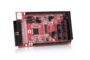
 Adam Feuer
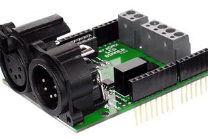
 Robert Mordzon
 ElectroBoy
Hi any plans to make more boards to sell? If I knew how to order PC boards I could do it myself but I have never done that before.