 James Ots
The Original Project
Many years ago, I had a stack of Z80 based computers — mostly RM 380Zs, and a few Cifer 2684s. Eventually I ran out of space, so I ripped out all the socketed ICs, put them in an empty margarine tub, thew out the computer shells and planned one day to use the ICs to build myself a computer.
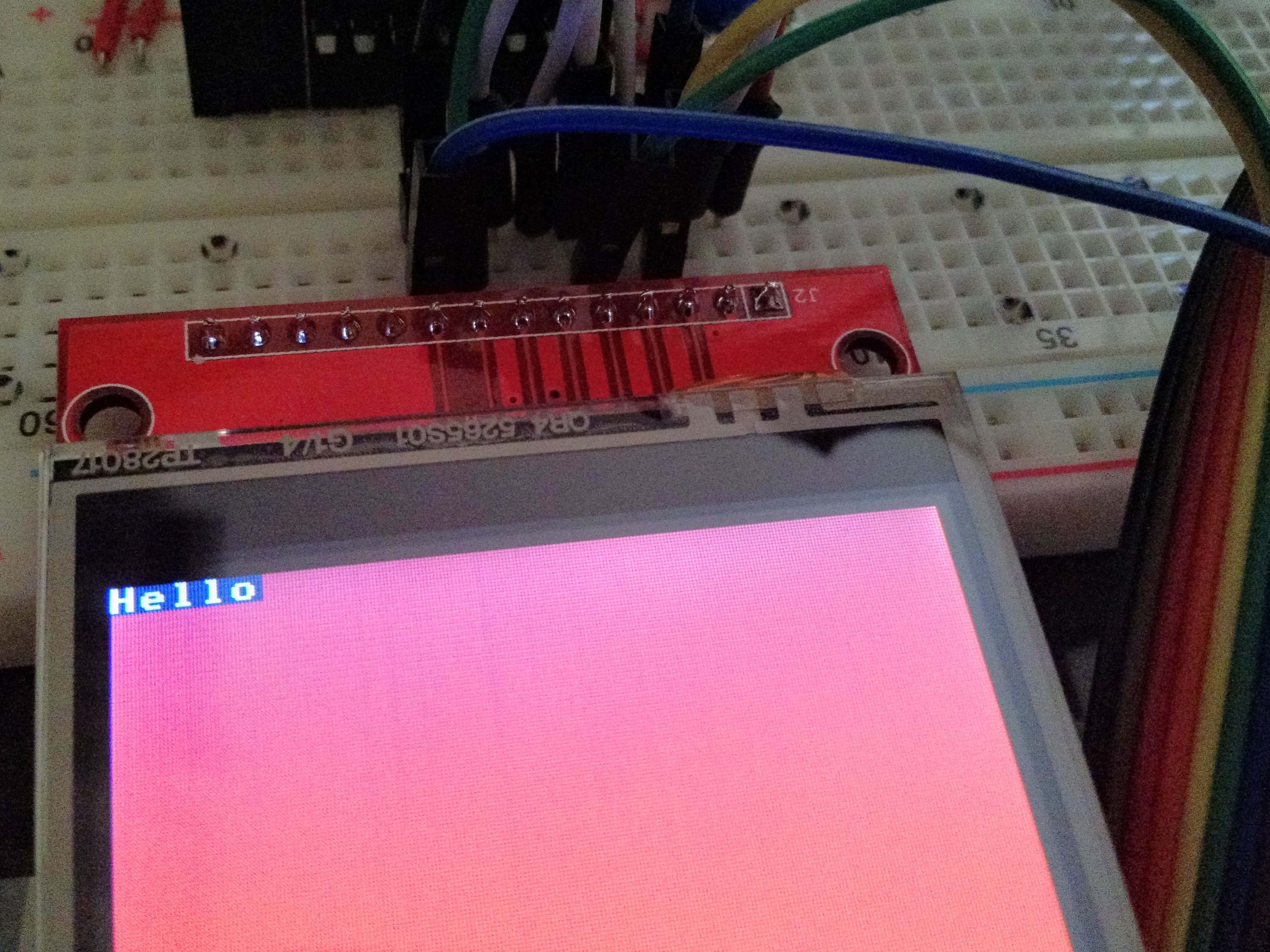
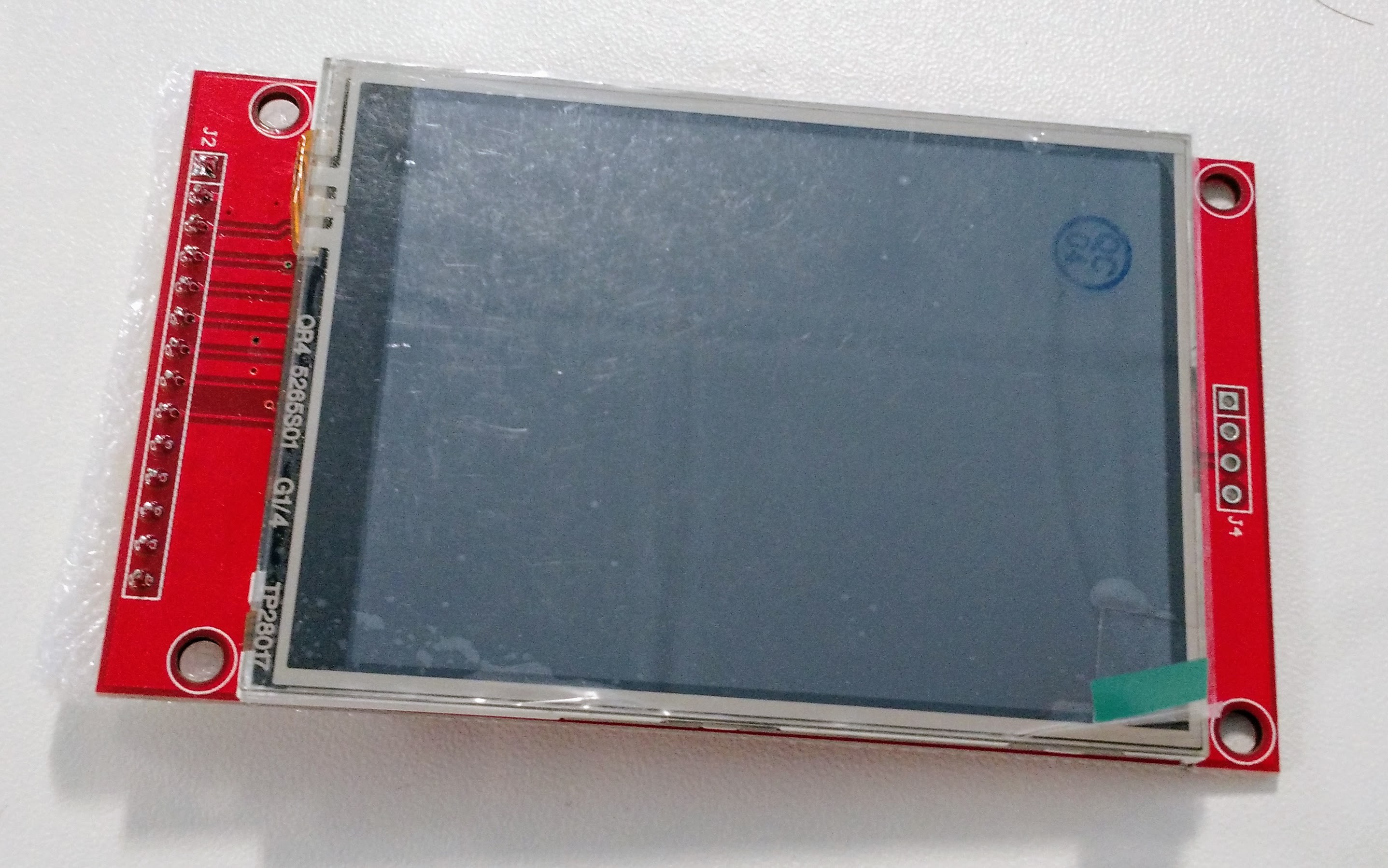
Although I now wish I still had the old computers, I can't do anything about that. But I eventually got round to building a new Z80 computer with the parts I had. My initial goal was to build a Z80 computer using only those parts, but I gave in and acquired a few extras — namely, a 4x16 character display, a buzzer, and FT245 USB-serial breakout board and a MAX70x power supply monitor. I initially used a single TMM2016P to give me 2Kb of RAM, but then bought a 512Kb RAM chip instead.
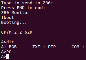
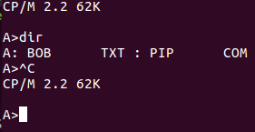
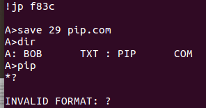
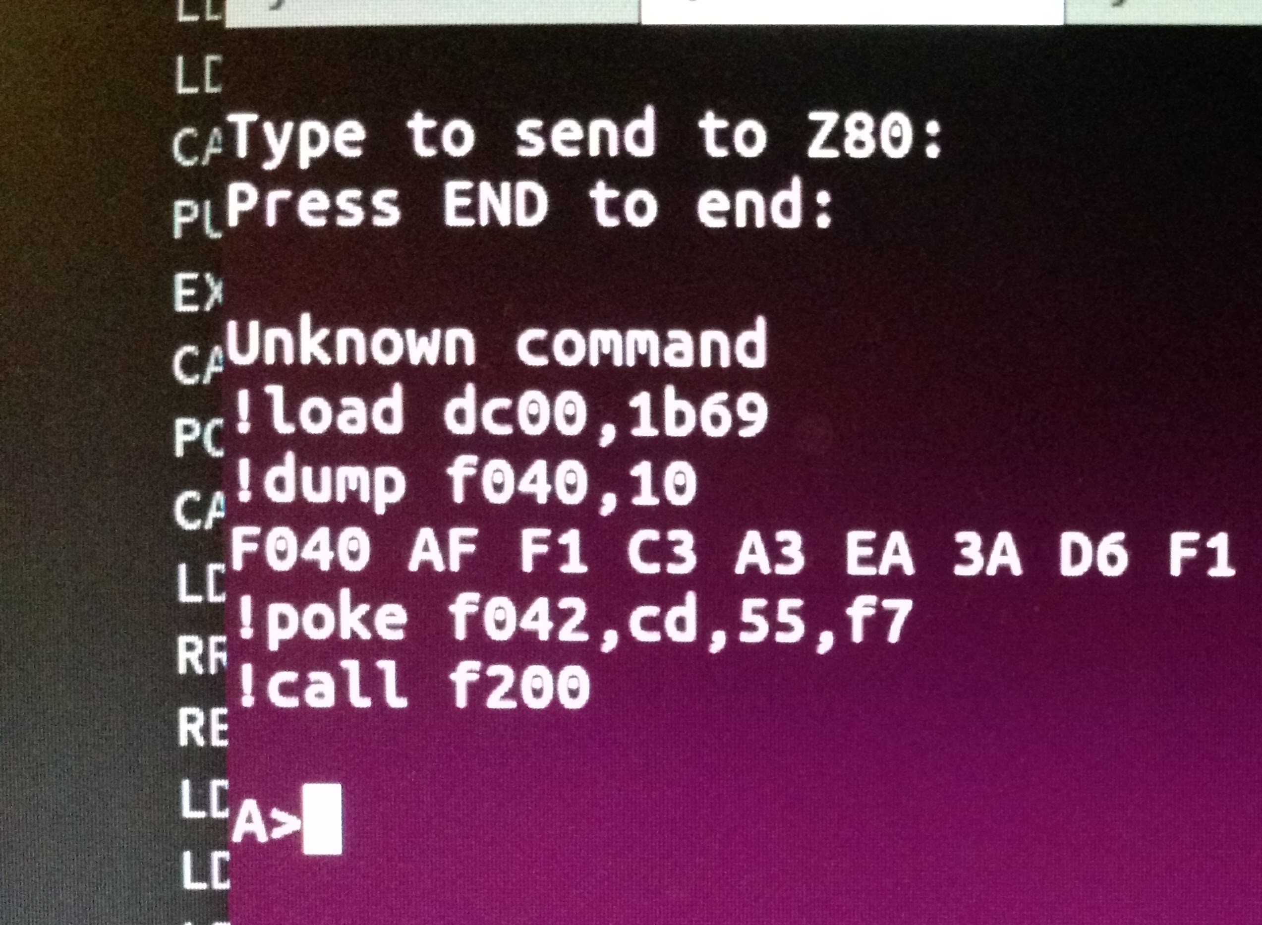
The memory map is divided into 4 16Kb banks, into which you can load any 16Kb page of the 512Kb of RAM, or you can map the FT245 into one of the banks — in fact, the FT245 is mapped into the first bank on startup. If you read from any address in the FT245's bank then WAIT states are inserted until a byte is available (send from the PC on the USB serial port). In this way you can bootstrap the Z80 computer by sending it a programme down the serial line. There is currently no way to send data back up the serial line.
You can send data to IO ports to write to the display or turn the buzzer on and off.
The New Project
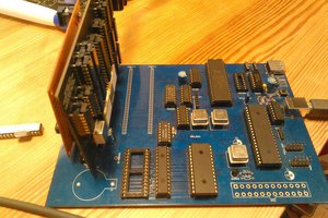
I now want to get my Z80 computer on a PCB. Unfortunately I would need quite a large PCB to fit all the components, which gets quite expensive, so I've decided that I'm going to replace all the glue logic with a CPLD. I have created a breakout board for the Xilinx XC95144XL, and, to my surprise, it works perfectly. So now I'm working on connecting the CPLD to the Z80 components, on a new breadboard.
My plan is to be able to run CP/M on the computer when it is finished. It will have at least 512Kb of RAM, 32Kb of ROM (I have the EEPROM, but I'm yet to try connecting it up), a screen, a USB serial port, either an SD card or CF card interface, probably a real-time clock, and maybe some other things such as battery backup.


 Dylan Brophy
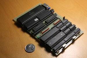
 Hayden Kroepfl
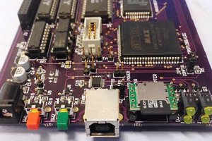
 tomcircuit
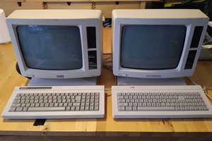
Got any 380z's left complete?