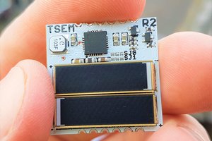
• Enclosure

    dhq05/16/2017 at 23:28 0 comments

    The main idea behind the solar mote is to affix it permanently on key locations inside a greenhouse.

    The PCB is held between two plastic enclosure pieces. The sensors are mounted on the mote headers.

    Below is a mock-up of the design together with the assembled mote. The solar panel is mounted on the other side.

    The plan is to use a hub based on an RPI. The range on the radios tested on the lowest power level is ~22 m.

  • Battery calculations

    dhq05/16/2017 at 00:29 3 comments

    The idea behind Open Solar mote is to use it as a greenhouse monitoring node. A LIPO battery was used. Now LIPO's require constant current for fast charging. This means that the battery can only get recharged when the solar panel is exposed to sun.

    Some calculations follow:

    •Imax = 100.38 mA (Approximate current draw by the system, worst case) •System wakes 60 times an hour •127.5 mAh battery capacity (accounting for leakage)

    Daily Consumption=

    24((〖Active Cycle〗_( per hour)×100.38 mA)+(〖Sleep Cycle〗_( per hour)×455 nA))=0.8131 mA/Day

    Life expectancy=(127.5 mAh)/(Daily Consumption)=157 days

    This is without recharging.

  • Solar Harvesting (from the bench)

    dhq05/13/2017 at 19:00 0 comments

    I am using a small solar panel for each mote. The specs are VOC = 3.3V and Isc = 100mA.

    To check the harvester capabilities I used the Analog Discovery programmable voltage source to emulate a solar panel output voltage.

    TI uses the term cold start to describe the point when the device starts to harvest energy. This is essentially a very efficient boost converter.

    With an input voltage of 366 mV it can be seen that the nano-power boost converter gets out of cold start mode. Since the PIC24 is capable of operating from 1.8V this in theory can work. The huge drops however means that the MCU will reset once the Brownout detector kicks in. This is slightly higher that the 300mV quoted from the datasheet. The best I could get from the various tests was 345 mV stepping it up in increments of 5-10mV.

    Ramping up the voltage to 494 mV and now we're in business. The output resistor as shown on the image below have programmed the buck to output 3V

    One thing to notice when playing with this setup is that you can't change the input voltage really fast otherwise the BQ25570 won't track the input and the output voltage will collapse.

    Ramping down the voltage up to 246 mV the output is 1.32V. This is not really usable for the system however.

  • Checking the PMIC

    dhq05/12/2017 at 00:41 0 comments

    Soldered the 2 first boards and took some measurements to verify the functionality of the PMIC chipset. The output resistor divider of the buck-boost circuit is programmed to output a 3V voltage. I hooked up a small LIPO battery and checked the power rails.

    It works! Next step is to verify the energy harvesting capability