 256byteram
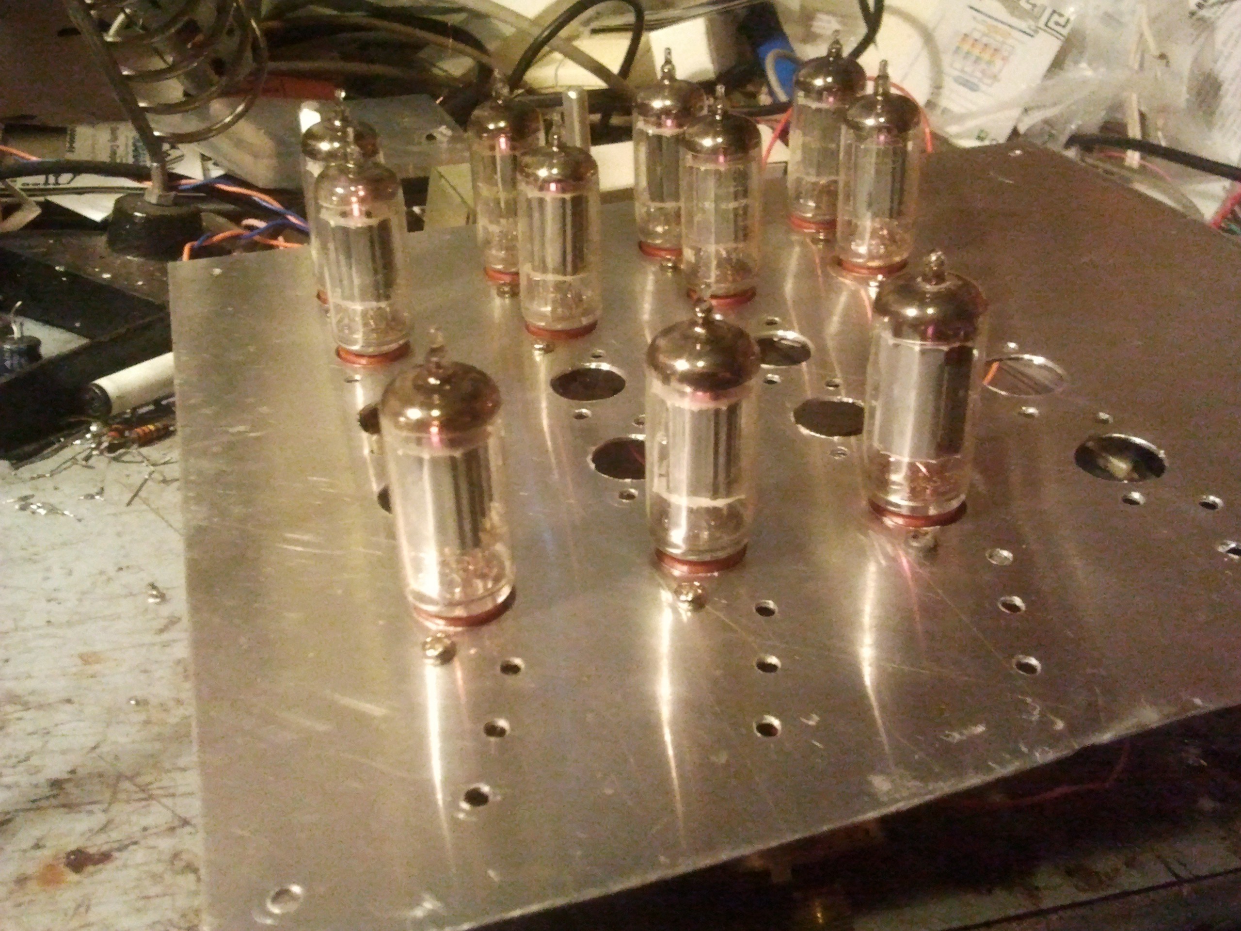
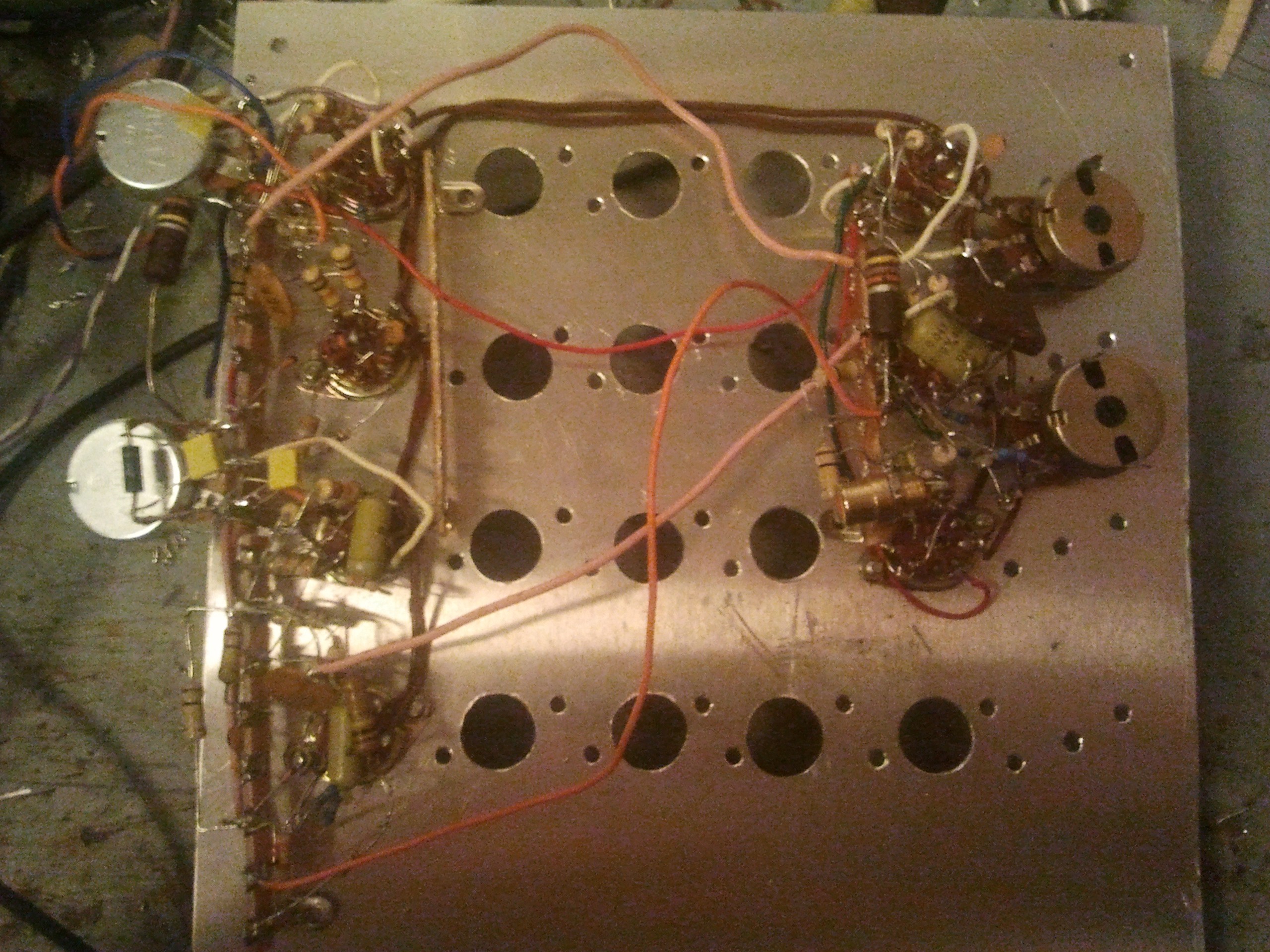
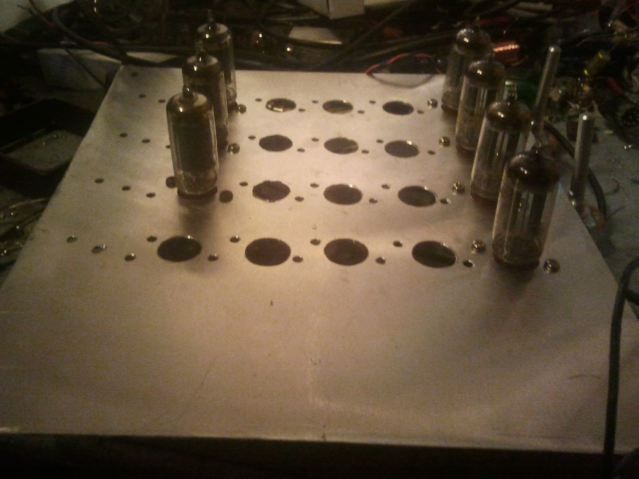
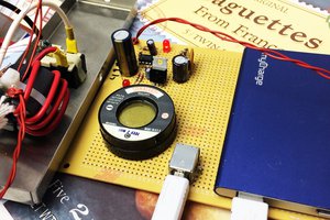
The whole thing is made up of multivibrators (aka one-shots and flip-flops). The idea is I start with sync oscillators for horizontal and vertical and trigger one-shots off them, then use diode logic to combine the output pulses of the one-shots.
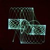
For example, to generate a vertical line, I start with a horizontal oscillator which produces a pulse acceptable to synchronise a television. The pulse triggers a one-shot who's delay can be varied with a voltage. When the pulse ends, it triggers a very quick one-shot which generates the line on the television. Varying the length of the intermittent pulse moves the position of the short pulse on the screen.
The same can be applied with a vertical timing. Using diodes, the outputs of the one-shots can be combined to produce a paddle or a ball, depending on the length of the pulses, by logically ANDing the outputs.
Currently the circuit works off a 100V regulated power supply (using tubes again) and draws about 30mA. I'm expecting the completed unit to draw over 300mA on B+ and 6A for the filaments.
I'll update the schematic as I go at http://kaput.hopto.org/~thrashbarg/TubeTVTennis.pdf
Some reading material I found useful:


 The Current Source
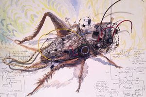
 Kelly Heaton
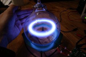
 sky-guided
can this tube help to show up the integrated tennis log? I want to test for the best tennis racquet program.