 WJCarpenter
My V3 PCBs arrived on Tuesday. Another quick turnaround from the PCB factory and DHL shipping. I wasn't quite as excited this time around since I was already expecting the quick delivery and I had only made small changes to the layout. Still, impressive.
Here's a view of the V3 board in the area of the microprocessor board:
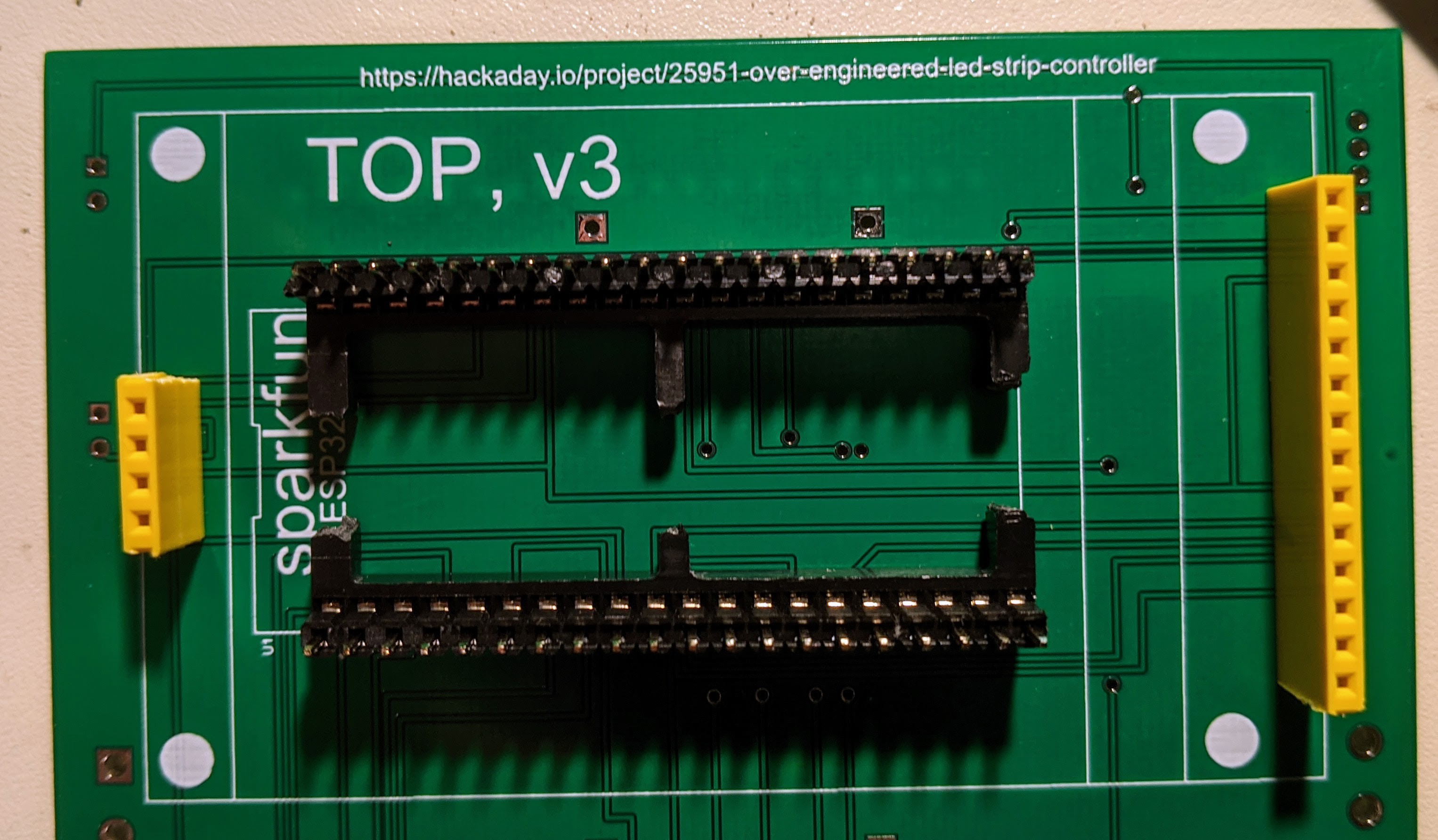
I have placed the female headers for the display board and the socket for the microprocessor board. You have to look closely to see that the short male header pins are inserted into the socket.
I verified that the east-west spacing was exactly as expected (described in my earlier project log) by placing the microprocessor board onto those short pins. However, with the micro-USB right angle adapter plugged into the microprocessor board, it blocked the display board pins from going all the way into the 14-pin connector. Without the right-angle adapter, things are more or less OK. The battery connector on the microprocessor board does press on the bottom of the display board, and the microprocessor board header pins are dangerously close to the metal SD-card holder on the back of the display board. I'm not using the battery connector, and it can easily be removed.
I haven't decided yet what I'm going to do about fitting things in the Z dimension. A couple of days ago, I ordered some 17mm male header pins just because I thought they might make things tidier, so that may take care of the whole problem. I'm hoping that I can leave the right-angle adapter in place and might be able to leave the battery connector intact, but I can sacrifice both if necessary. Since the microprocessor board is socketed, I can simply remove it if I need to do a firmware update over USB. (With this new V3 spacing, some normal micro-USB cables can be snugly inserted if the display board is removed.)
Discussions
Become a Hackaday.io Member
Create an account to leave a comment. Already have an account? Log In.