 Radu Motisan
Introduction
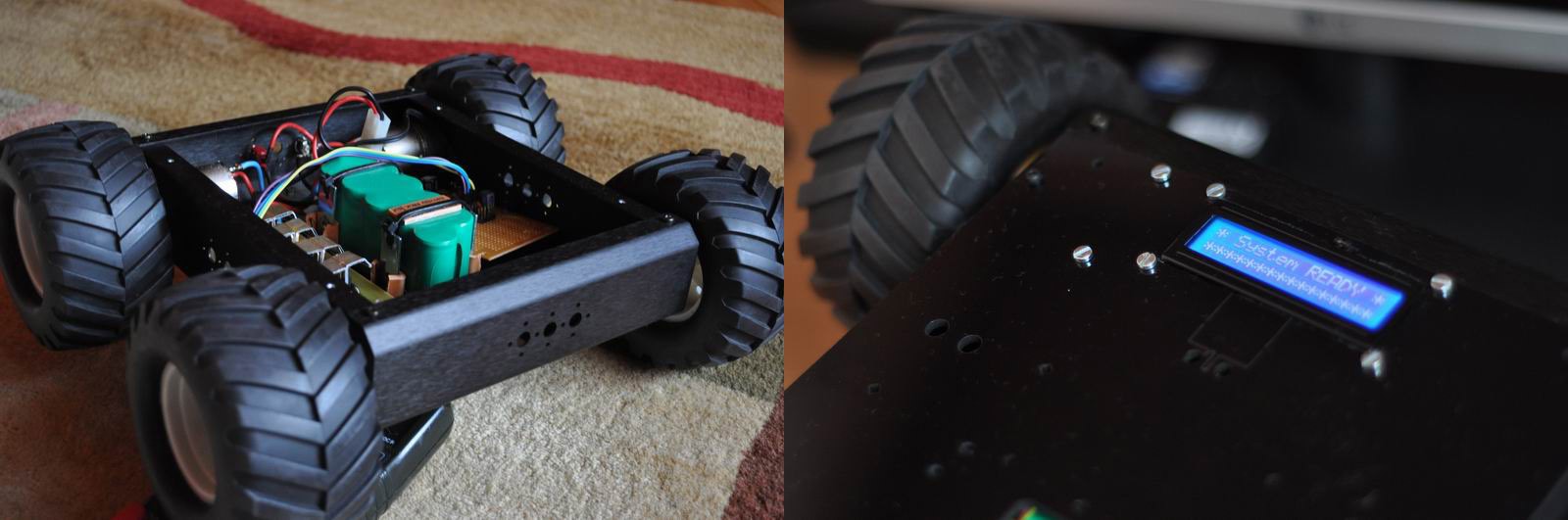
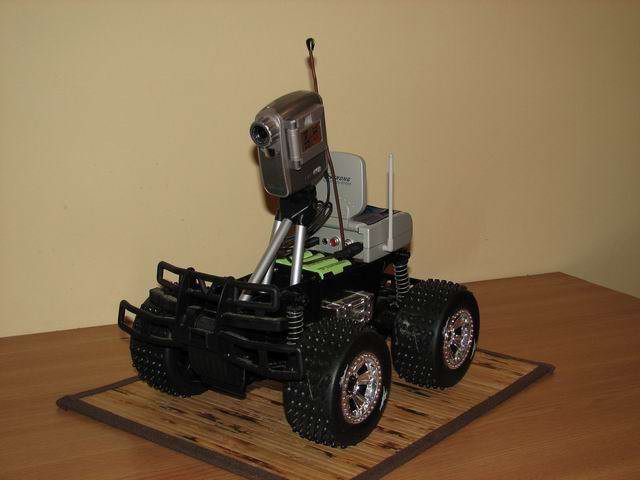
Some of the work on this technology started back in 2013, when I built a custom Robo-dog as a proof of concept. We'll call it version 1. It also became featured on Hackaday, unfortunately Mike Szczys only focused on the bluetooth remote control, a secondary feature. The user tracking tech in this project is by far more appealing:
There are several ways of tracking a user, depending on application. To start a lamp in your yard during night it is sufficient to use a PIR sensor. To create a #Robo-Dog, a system that follows its user while walking or running is a challenge requiring localisation in a 2D space.
If we take this further and try to design a SWARM system, there we'd have drones needing to be aware of each others in order to keep distance and enrol tactical plans together. There a more complicated 3D space localisation mechanism would be required.
But getting back on the ground, there are several approaches we could consider:
1. the robot has a camera, and recognises the user using some software algorithm. Eg. the color signature (simplest) or a pattern. Or the user's face (using OpenCV), or using Optical Flow to track the movement of pre-defined parts of image (eg. user's hand). This is easy, but has it's issues including dependency on lighting conditions and high processing requirements. For humans, it's the way we go to recognise others and do various actions, so this is tempting because evolution has proved it right.
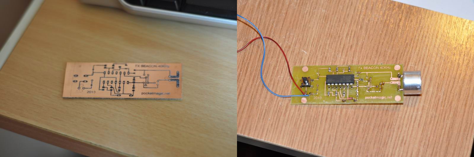
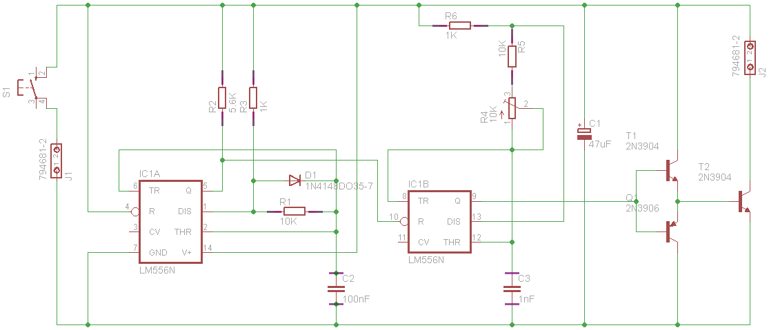
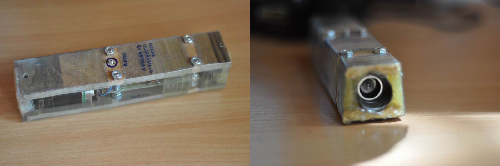
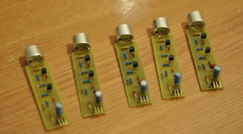
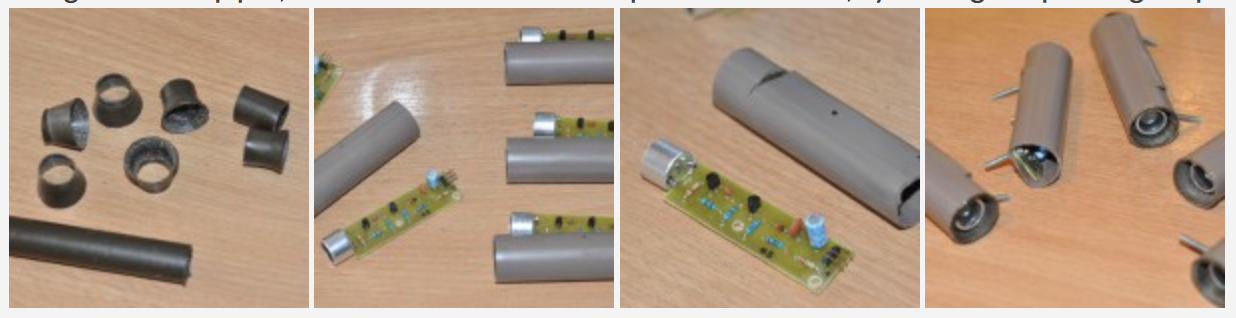
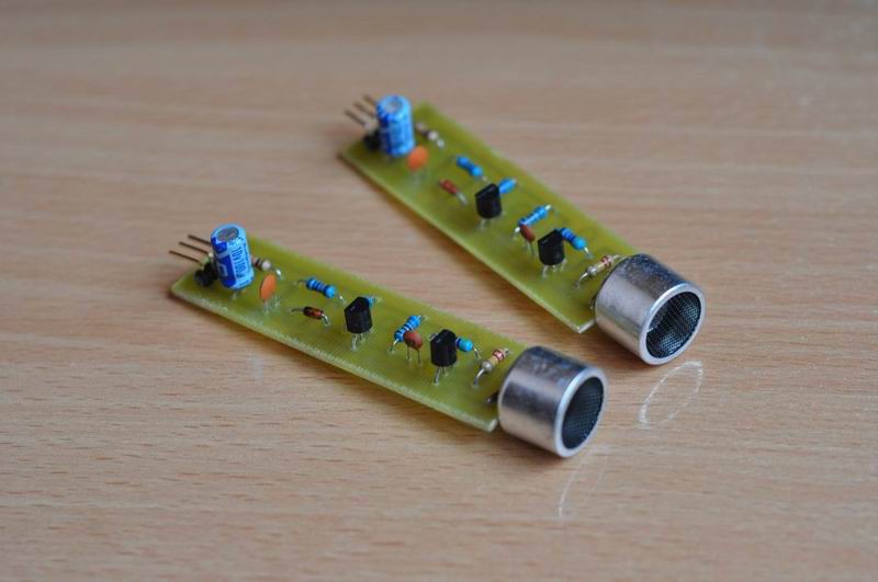
2.using beacons, the user signals it's position and the robot receives the signal using some differential system (Eg. two antennas). By doing so, the robot will be able to track the source of the signal, so it knows where the user is and can track it.
3. the robot has a LIDAR and knows the environment. At start it can locate the initial position of the user, then react when the user starts moving. Surely, if the user would intersect with other actors, things could complicate even further.
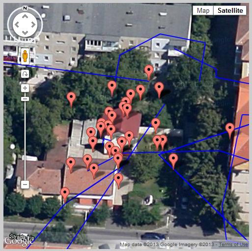
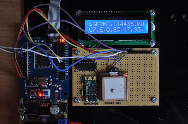
4.the robot has a GPS receiver, the user has one as well, and they both intercommunicate (eg. via radio waves: bluetooth , etc), to exchange coordinates. The robot will then simply move to approach the location of the user. This is a straightforward solution, but the GPS localisation has errors, preventing use as required by this project, unless some special error-correcting mechanism is implemented in software.
Applications
A robot that can track its user is more then a toy (but imagine metallic dogs running to bring the ball back in the close future). Such a system is useful to build robot assistants in factories, carrying heavy parts and tools, in military operations carrying equipment or the wounded, automated shopping charts in malls, or even automated strollers (I recently learned how much I'd love that). The applications are endless, and so a reliable robo-dog technology would be adopted quickly to most of our daily lives.
Implementation
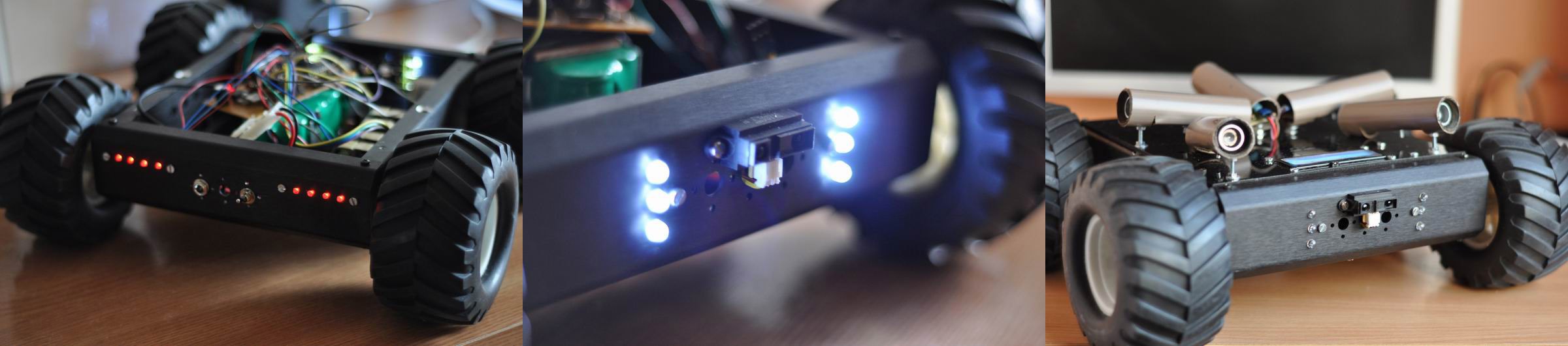
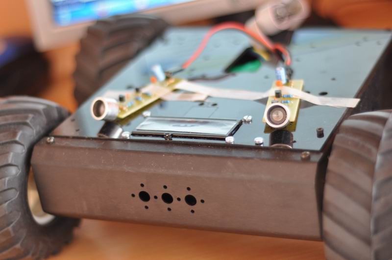
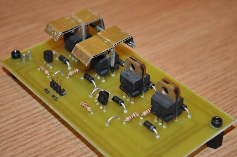
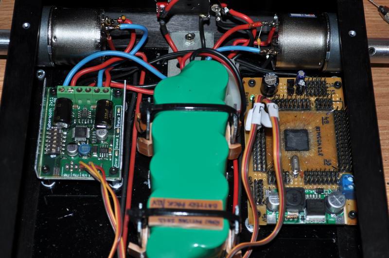
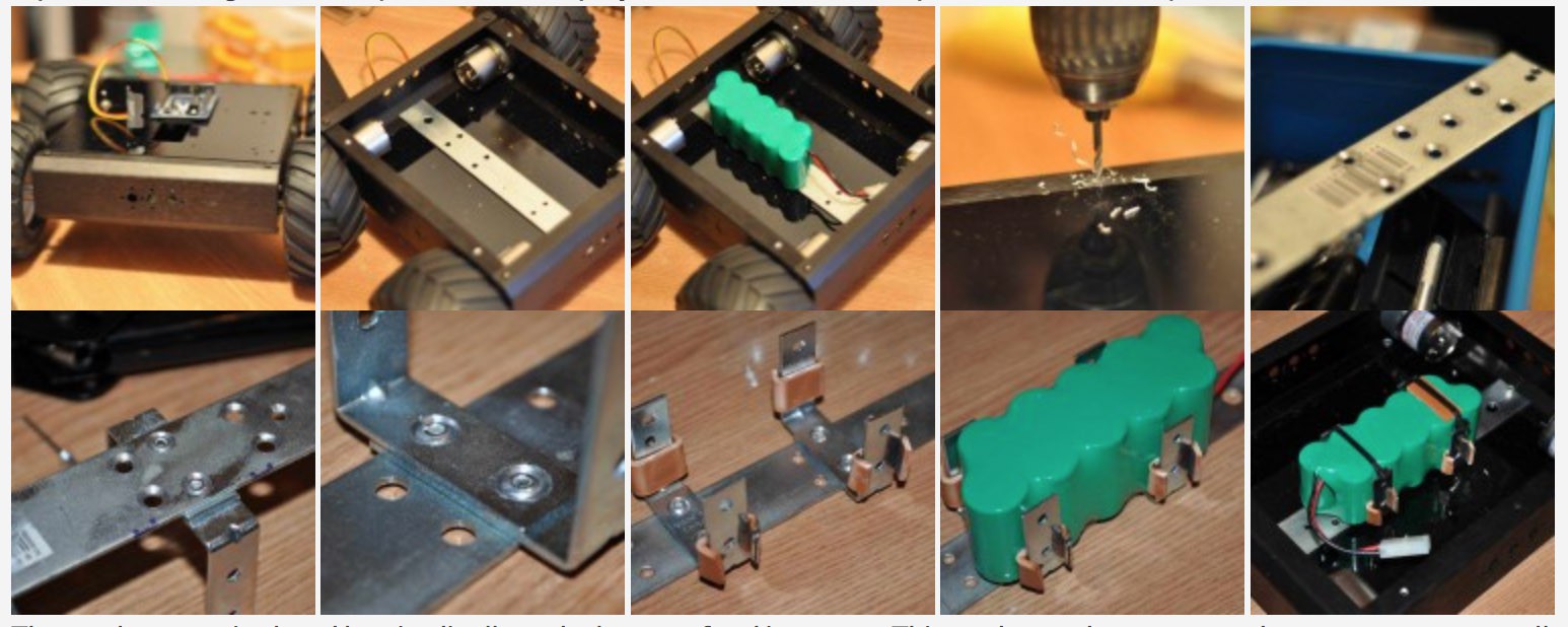
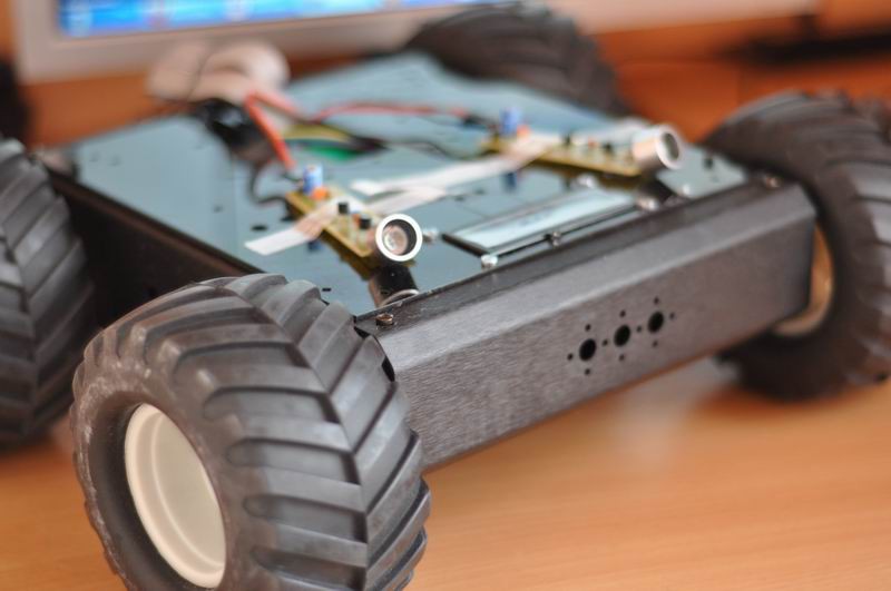
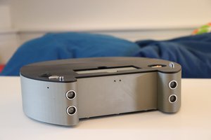
I will use a differential rover chassis to implement a solution to these requirements.


 Lars
Lars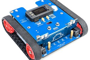
 Alexander Kirillov
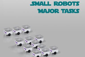
 Rodolfo
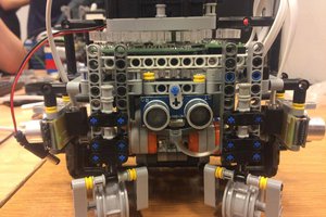
 maks.przybylski
hey thats great, my father is an automobile engineer he made a dog that works with Ai(code) the commands like to open door come here etc it seem like this.