Close
0%
0%

FPGA based robot vacuum cleaner

3D-printed cleaning robot based on an fpga.

Similar projects worth following
This is a 3D-printed cleaning robot based on an FPGA. The robot has several sensors to detect obstacles and a suction unit to clean floors.
To drive through the apartment it uses an algorithm which works according to the chaos principle.

I try to incorporate the following aspects into the design:

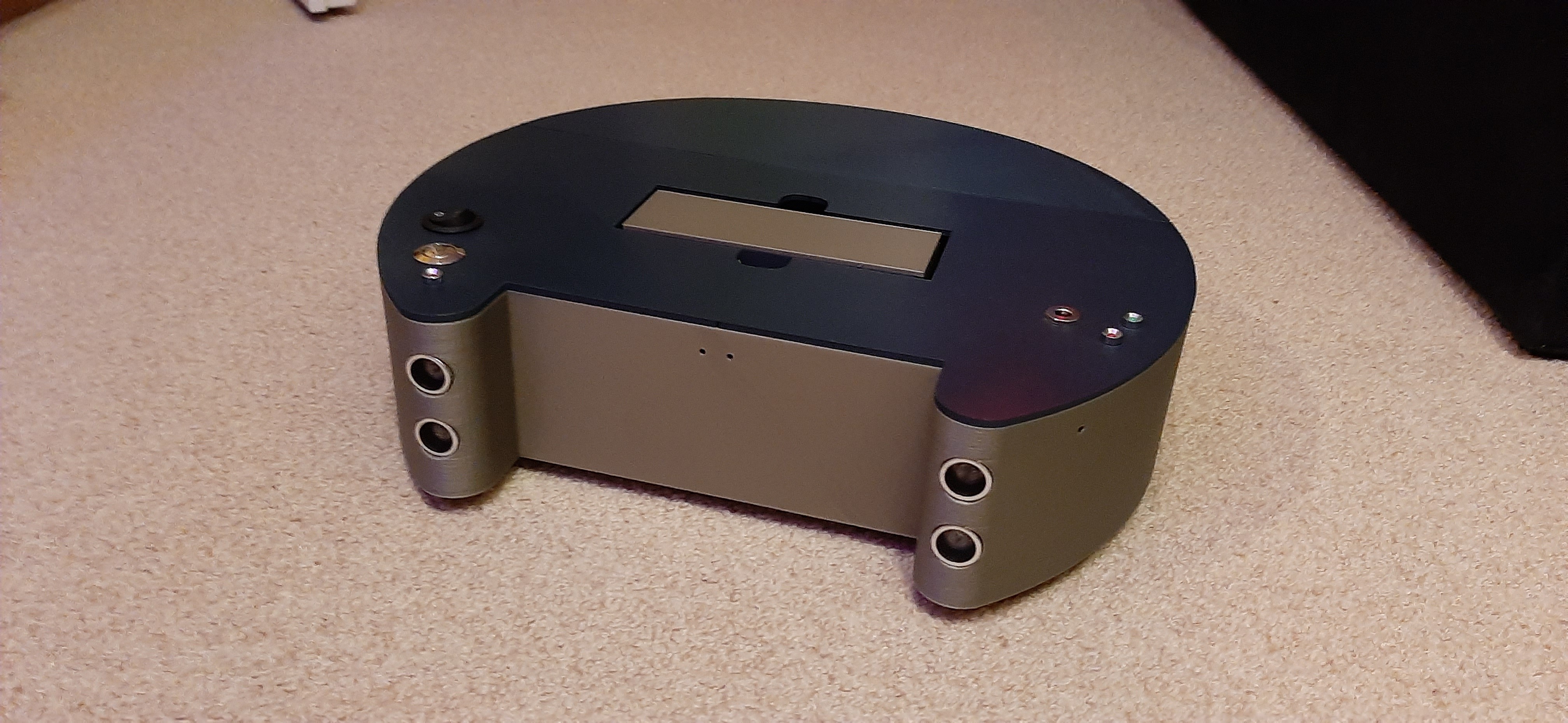
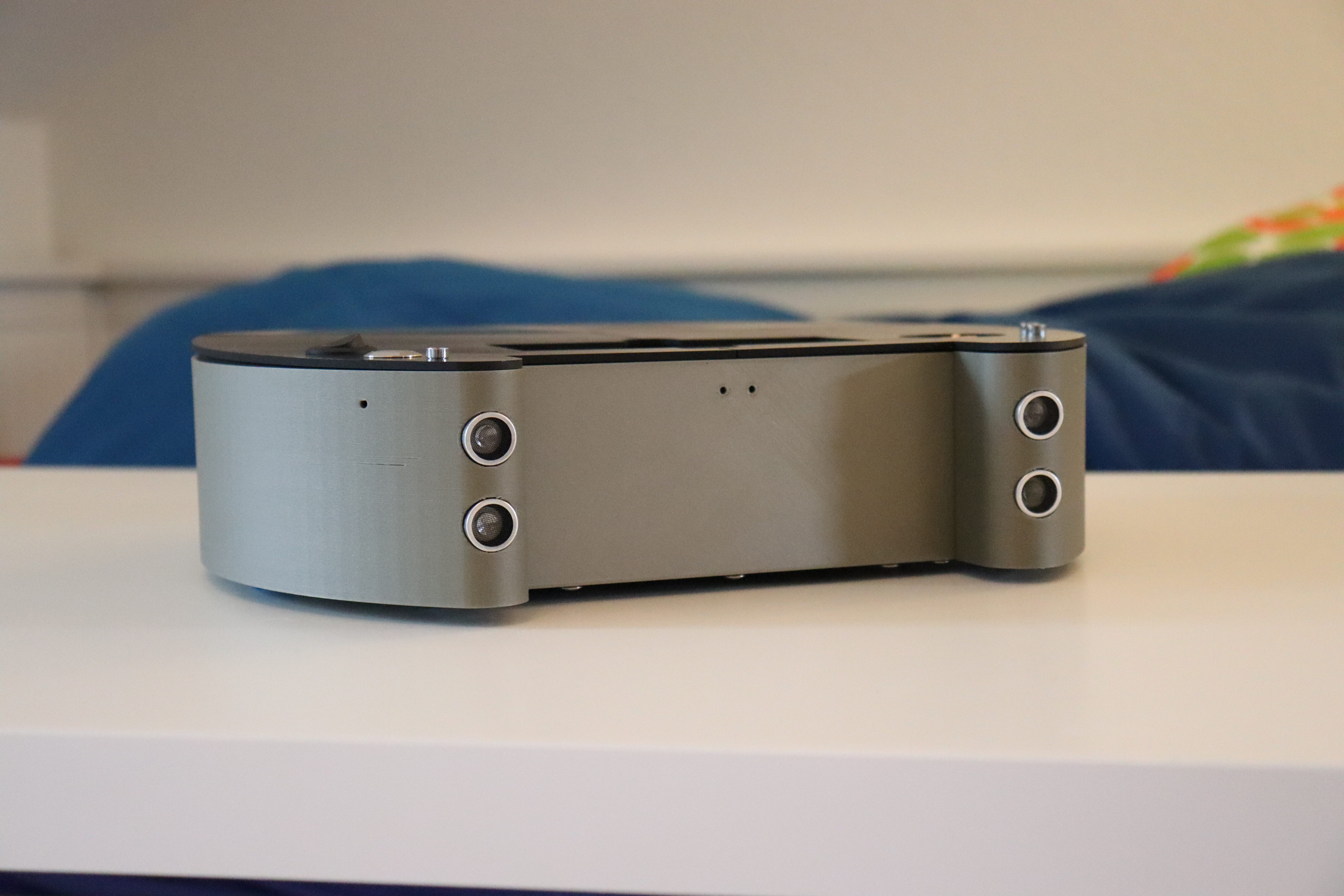
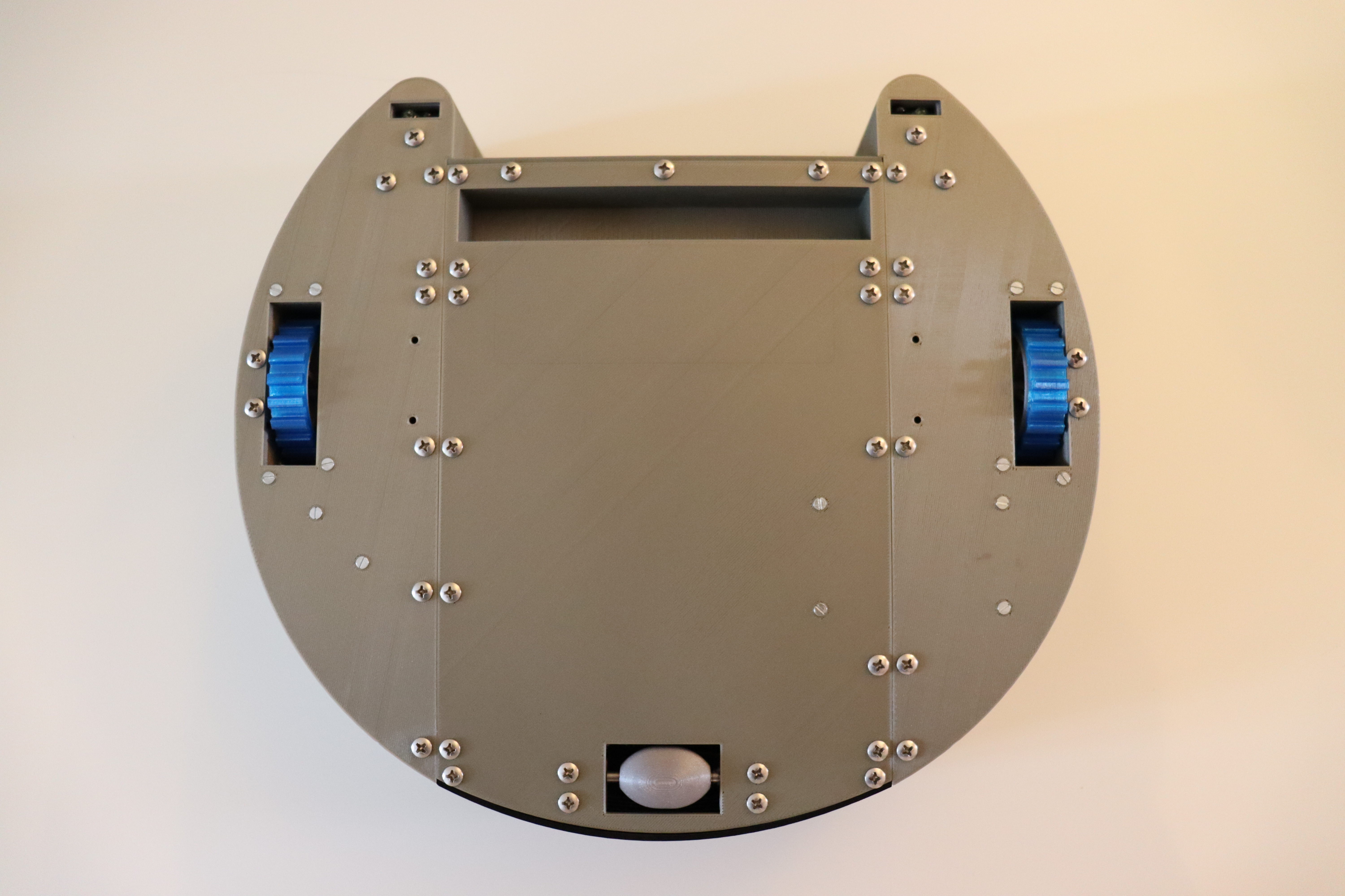
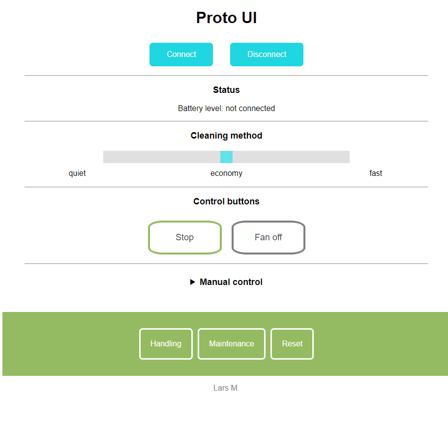
  • A pretty important aspect of every design is functionality. The robot should be able to do what its name suggests, without the need to study manuals


  • Intuition. Intuitive operation and high functionality lead to frequent use of the device. Therefore the robot should be as easy to control as possible, to actually use it effective in everyday life. It would also saves time to use it for something more important than floor cleaning. Maybe to create more vacuum robots.
  • Safety. This aspect should not be ignored either. Safety means, that the robot should not accidentally fall downstairs or behave unpredictable.
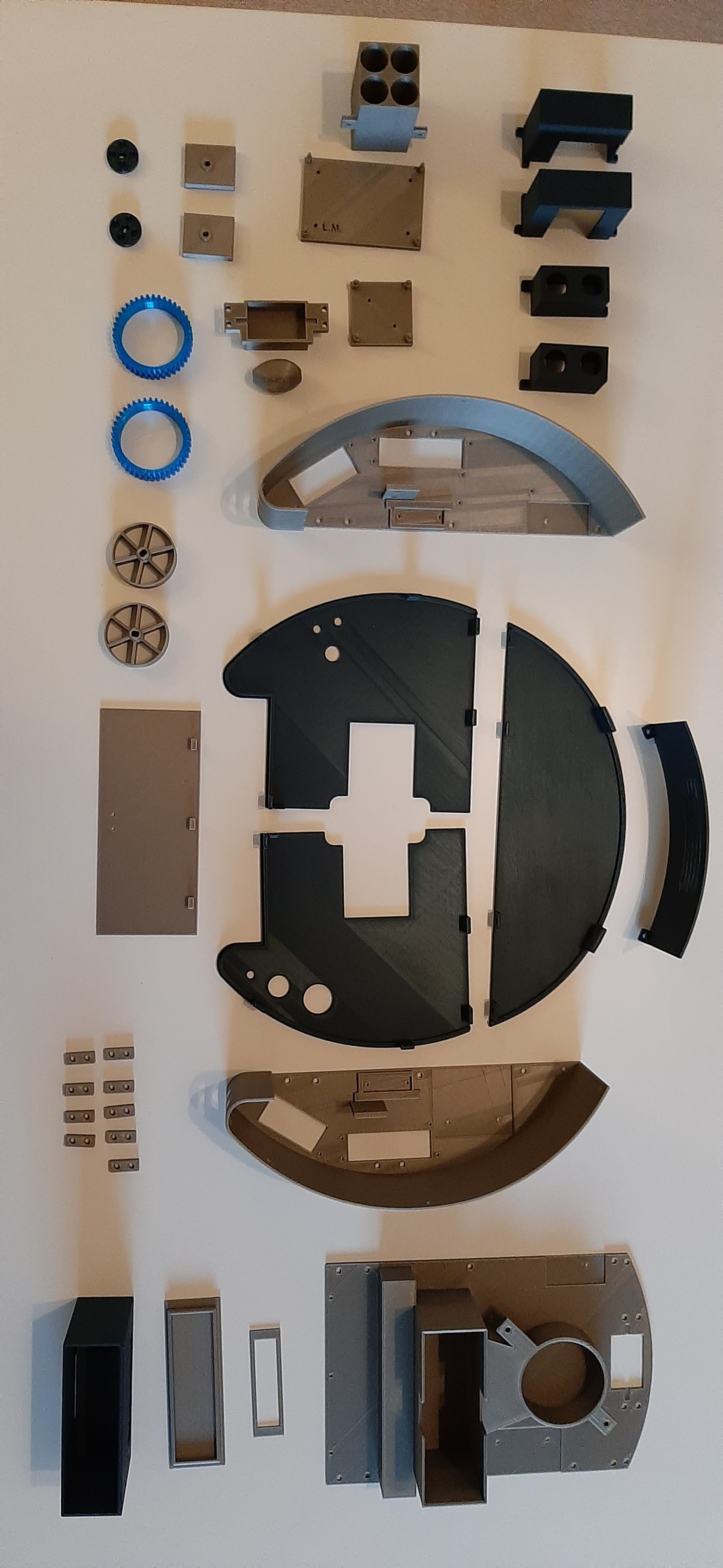
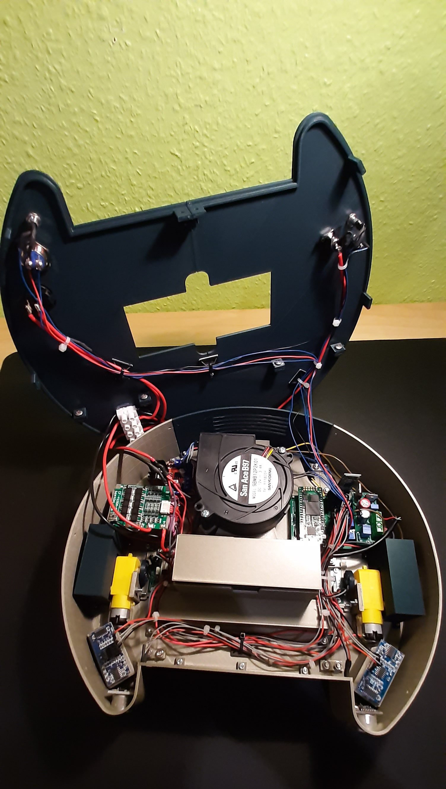
  • Fun. This is the main reason why I started this project. I am learning a lot by working on this vehicle. The special thing about building a robot vacuum cleaner is, that there are so many different areas in which you further educate yourself during construction. In addition to electronics, I learned a lot of things about mechanics and 3D printing, which I subsequently applied to other projects. You really don't find such a variety of topics in every project.

Adobe Portable Document Format - 57.99 kB - 04/30/2020 at 18:17

Preview
Download

View all 7 components

  • Generation 3 + end of project

    Lars10/31/2020 at 17:21 0 comments

    Since August, the 3rd generation of this robot project is completed. This is the last version of the vacuum robot, which brings the project to an end. The new vehicle looks quite similar to Gen2, there are only a few improvements:


    - More accurate determination of the battery level
    - Greater distance between floor and housing. This allows the robot to crawl on carpets.
    - 4S lithium-ion batteries with battery management system for more safety
    - Own battery charger


    I have gained a lot of experience from the development of these robots. I will now use this experience for a new robotic vacuum cleaner with new challenges. I have already been working on the design of the new robot for several weeks and developed a 2d-lidar solution. 

    More information will be published in a new project entry when the time comes.

  • Gen 2 is ready!

    Lars06/30/2020 at 18:53 0 comments

    I have now finished the build of the second generation fpga based vacuum robot . 

    The following improvements were made:

    • Higher suction power due to better sealing
    • Webapp with several cleaning functions
    • Lower height of about 7 cm => doesn't get stuck under low furniture so often anymore
    • 50 min charging duration by using LiPo- rechargeable battery
    • Improved navigation algorithm (still chaos principle)
    • Staircase detection through cliff sensors
    • Low battery alarm and automatic shutdown (using a comparator IC instead of an ADC)

    Here are some pictures of the new vehicle:

  • Hall sensors as encoder

    Lars06/30/2020 at 18:41 0 comments

    As mentioned in a previous entry, the robot is using two revolution counters, one on each wheel. The encoders are not directly connected to the wheel, but to the motor drive rod. The drive rods are then immediately linked to the wheel.

    The encoder have several purposes in this project. On the one hand they are used to monitor the wheel rotation. If the robot detects an object, depending on the scenario, a value is stored in the FPGA, which describes how far the vehicle should turn. Therefore, the encoders can be used to detect whether the "programmed" behavior has been applied and the preset angle of rotation has been reached. If this is the case, the robot can continue its journey.

    The encoders can also be used to detect when the wheels are no longer turning, i.e. when the rotational speed is zero. If this is the case, the FPGA again compares the actual state with the target state of the wheels: If the wheels do not turn (actual state), but the state "driving" was stored (target state), an error has occurred. This error is usually caused by the robot getting stuck.

    Future applications could be a sort of mapping system for measuring different rooms. The position of the robot can be determined by the number of wheel rotations.

    The structure:

    The revolution counter unit essentially consists of 2 components.

    1. The magnet plate consists of 3d-printed PLA and contains 4 neodymium magnets each. They are arranged in 90 degree angles to each other. Please note that the south pole of the magnet is mounted towards the sensor, because the Hall sensor I use only detects positive magnetic fields.

    2. Hall sensors are sensors whose output signal depends on the surrounding magnetic field. They therefore detect the magnetic fields and then change the electrical state of their output. In order to evaluate the output signal with the FPGA, the Hall sensor must be connected correctly. For the robot I use a unipolar Hall sensor of type H501. Unipolar in this case means that the sensor detects only the positive pole of a magnet.  The output gets a high state when a positive magnetic field is applied and drops to GND when this field is no longer present.

    Another important feature is the Schmitt trigger. This is a comparator circuit that converts a linear output signal into a square wave signal so that it can be read by the FPGA. It is important that the sensor has this circuit; otherwise it must be built externally.

    The sensor is powered by the 3.3V on-board power supply of the robot. The small foil plastic capacitor is used for interference suppression. The output signal requires a pull-up resistor with a value of 100k. 

    I then transferred this circuit to Eagle and ordered the circuit boards. The PCB fits well into the holder provided for it in the robot.

    Behavior of the sensor:
    State at output:         Condition:

    0 => no magnetic field
    1 => Positive magnetic field

    The note shows that the sensor can detect two states. If the sensor does not detect a magnetic field, a low level is present at the output. A high level only occurs if the south pole of a magnet is detected by the sensor. When the magnetic field is no longer present, the output falls back to low. 
    This behaviour can be easily seen on the following extract of an oscilloscope diagram. The square wave signal shows the output of the Hall sensor while the robot is moving:

    This diagram shows the voltage at the output of the hallsensor over time (ms). You can see the periodic square-wave signal that is generated by the consistent movement of the wheels.

  • Autonomous driving attempt #2

    Lars06/21/2020 at 08:55 0 comments

    I have now managed to conduct an official second test. Of course, I have tested the robot many times before, but I didn't have enough time for a complete test with camera and setup. The current test was performed with an optimized navigation algorithm. The control unit was described in VHDL as mentioned before. The whole system is running on a TEI0003 development board equipped with a small but powerful Cyclone 10 FPGA.

    The entire board computer of the robot is based on this small FPGA board. There is no microcontroller built into the vehicle. Except for the JavaScript-based web application, which was explained in the last article, this project does not include any software application. This is not because I don't like software programming, but because I am an absolute FPGA fan.

    The attached video shows the new test. The test was performed in three runs. In the first test the robot was placed in a small room without objects. In the second room there were one and in the third room 2 obstacles.

    By close observation you can see that the robot reacts to various situations with different behavior. When it detects an obstacle, the vehicle compares the distance between the two ultrasonic sensors and moves in the direction with the greater distance.

    The following changes were implemented in the navigation algorithm:

    • The robot no longer features a constant angle of rotation. This means that if the vehicle detects an obstacle through one of the two ultrasonic sensors, it will not continuously perform the same movement with a constant angle of rotation. Instead, data is loaded by a state machine out of an array that stores several possible maneuvers. The state machine of the navigation algorithm includes a counter that increments the address of the array by 1 after each maneuver, so that different rotation angles can be used to avoid an obstacle.
    signal 	rom_addr:	integer range 0 to 4 := 0;
    constant rotation_rom: rotation_rom_array :=(2,3,4,5,6); 
    
    • If the robot gets stuck, it drives a small predefined distance backwards, so the vehicle can usually escape from the unfortunate situation.
    • When the circuit in the FPGA detects that the robot is desperately stuck, fan and motors are deactivated, and the robot waits for the owner's help.
      • In the second generation of the robot the user should also be informed by the web application about the current state of the vehicle (working, stuck, etc.)

  • WebApp with Bluetooth low energy connectivity

    Lars05/20/2020 at 09:23 0 comments

    The real user interface

    As you can see in pictures of the robot, there are a few control elements on the roof of the vehicle which form an interface between the technology and user. In short, the user can give commands to the robot via the user interface, i.e. tell it what to do. The robot's user interface is kept very simple, so that hardly any previous knowledge is required. The vehicle has only one switch which can be used to turn the device on or off. Additionally, there is a grey pushbutton to restart the robot. The Status of the battery can be indicated by the green and red LEDs. The last element of the interface is a yellow LED which lights up in case of certain errors.

    The virtual user interface

    So far so good. However, there are several settings that can theoretically be made available to the user. As an example, the user could adjust the power of the fan himself so that a more individual operation can be guaranteed. The user could adapt the robot better to his own needs or circumstances. But since there isn’t enough space, no other buttons or switches can be mounted on the robot to add further functions.

    A solution to this problem is to use devices that almost every user owns. A mobile phone or PC, for example. Because of this I decided 2 weeks ago to program a web application which can be seen as another user interface. To communicate with the robot, Bluetooth low energy (Ble) radio technology is used. To receive data, an HC-08 Ble module is integrated in the robot.

    The idea for this project came to me through a presentation on the "Google Developers" YouTube channel. There is a detailed report about Physical Web and Bluetooth web applications.

    The website can therefore be used to send and receive commands to and from the robot via Bluetooth. The web application can be accessed in the browser. To communicate with the robot, you must activate the location and Bluetooth on your smartphone. 

    The website can therefore be used to send and receive commands to and from the robot via Bluetooth. The web application can be accessed in the browser. To communicate with the robot, you must activate the location and Bluetooth on your smartphone. 

    With this second interface, further settings can be defined by the user. After login, the user is redirected to the start page. First, there are the "Connect" and "Disconnect" buttons, which can be used to initiate or terminate a Bluetooth communication. Below the Bluetooth buttons the battery capacity is displayed. In order to control the fan power, there is a slider under the status bar. With the two "Controlbutttons" the main functions of the robot can be managed. Each of the buttons has two functions: The left button is used to switch off the robot. When the button is pressed, its text field changes over to " enable autopilot". If you push the button a second time, the robot can be started again without the need for multiple buttons in the same application. This fact also applies to the "Fan off" button, as it allows the fan to start again after deactivation.

    It should be considered that the available code works well but is improved from time to time. The latest version will be available on Github soon.

    The HTML code for the start page is as follows:

    <!DOCTYPE html>
    <html>
    <head>
        <meta charset="utf-8">
        <meta name="viewport" content="width=device-width, initial-scale=1">
        <link href="styles.css" rel="stylesheet">
    </head>
    <body>
    <h1>Proto Lite UI</h1>
    
    <button id="connect" type="button">Connect</button>
    <button id="disconnect" type="button">Disconnect</button>
    <hr width="55%" />  <!--Trennstrich-->
    
    <div id="terminal"></div>
    <h3>Status</h3>
    <p  id="target">Battery level: not connected</p>
    
    <hr width="55%"/>
    <h4> Fan power</h4>
    
    <input type="range" min="0" max="10" value="5" class="slider" id="sliderAmount" onchange="updateSlider(this.value)">
    
    <h4>Control buttons</h4>
    <input type="button" id="launch" value="Stop"...
    Read more »

  • Ultrasonic sensors for obstacle detection

    Lars05/07/2020 at 15:42 0 comments

    Today I want to continue with the basic system of the robot.

    The article is structured as follows:

    • Basics
    • The Sensor
    • Communication and behavior

    Basics

    Ultrasonic sensors can be used for distance measurements. They can detect objects without touching them and then output the distance from the object to the sensor. Therefore, the ultrasonic sensor generates a high-frequency sound wave of approximately 40 kHz. Ultrasonic waves spread out at an approximate speed of 343 m/s, which is roughly the speed of sound. Another characteristic of a sound wave is, that it is reflected after a collision with an object. This creates an echo that can be detected by the sensor.

    The distance to the object can now be calculated from the time between sending and receiving the frequency.

    s = (v*t)/2

    s = distance in m

    v = velocity in m/s = Speed of sound(343,2m/s)

    t = time in s

    The sensor

    In the robot two HC-05 ultrasonic sensors are used. This sensor is characterized by a distance range from 2cm to 400 cm. The measurement result has a maximum deviation of +-3mm. A complete measuring interval has a duration of 20ms. This results in a maximum rate of 50 measurements per second. In addition, the sensor is also specified by a current consumption of about 15mA in normal operation. 

    Based on these characteristics, it can be said that the module is suitable for applications in a robot.

    HC-SR04 ultrasonique de Distance Télémètre / Obstacle Detection ...

    Read more »

  • Project Update​ 28.04.2020

    Lars04/28/2020 at 07:24 0 comments

    This is only a short update about the current status of this project. 

    Right now, I am fixing a few flaws in the design files of the robot.

    First, I changed the suction unit, because a lot of air still leaked out in some places. In addition, the suction opening underneath the robot was enlarged, because long hairs were still partly stuck. Then I decided to use a LiPo instead of a lead battery. I have written down a few important aspects which should be considered when deciding.

    The main reason is that LiPo batteries are way lighter than lead batteries. For comparison, the currently installed lead battery weighs about 890g. It has a capacity of 2300mAh. The LiPo battery I want to use weighs only 219g and has a capacity of 2600 mAh.

    Furthermore, the LiPo battery is only 2/3 the size of the lead battery.

    Also an important note is, that LiPo batteries are somewhat more expensive than lead batteries. But the price difference between the lead battery and the LiPo battery for the robot is only about 5 euro. That’s why I think the price difference is manageable.

  • ​ Autonomous driving attempt #1

    Lars04/18/2020 at 10:07 0 comments

    The video in this log shows the first regular test of the autonomous driving unit during the suction process. For the test track I used some old boxes and crates as walls. Normally there are also free-standing objects in a room, but these were not considered in this test.

    For obstacle detection, the vehicle uses only the two ultrasonic sensors mounted on the front. Because they can't see everything wheel encoder were attached to both wheels. They are based on four small neodymium magnets which are attached in a circle. A Hall sensor detects the magnetic fields and emits an electrical signal accordingly. The FPGA counts the wheel movements and can therefore determine how far the robot has turned.

    Since only 2 ultrasonic sensors are used, I had to think of a way to detect the objects in the blind spot. If the robot collides with an object that is outside the range of the ultrasonic sensors, the robot stops. Due to the weight of the robot, the wheels are no longer able to turn. That’s why I have implemented a deadlock detection in the fpga.

    The fpga stores the current and previous value of the hall sensors in flip flops. If both values remain the same, a counter is started. If the output of the counter exceeds a certain value and the values of the hall sensors have not changed, it can be assumed that the robot is not moving. Then the wheel condition is compared with the fsm for the motor control. If these two states are contradictory, the robot is stuck.

  • Project introduction

    Lars04/17/2020 at 12:02 0 comments

    Project history

    As I mentioned in the project overview, this project consists already for a while. Right now, I am currently working on Proto Lite - the third-generation prototype. The first version was a test prototype for autonomous driving and sensor testing. The second prototype, on the other hand, was used to investigate the cleaning properties.

    The third version consists of the main functions from the prototypes. Simply put, the robot should clean and drive. (There are of course other requirements, such as those from the project overview.)

    Electronics

    The electronics are based on an FPGA, which executes all processes to control and monitor the behavior of the robot. It communicates with the motor drivers, controls the sensors, evaluates their data and converts them into useful information. This information can then be used to draw conclusions about the behavior of the robot under certain situations such as obstacle detection.

    Because you don't program an FPGA (like an Arduino), the robot has no software program. Instead, a bitstream file containing the circuit and all other specifications (clock, IOs) is loaded into the FPGA's configuration memory. The FPGA is then configured to create the desired circuit.

    I have written a code in the hardware description language VHDL which describes the circuit of the on-board computer. This code can be synthesized and loaded into the configuration memory of the FPGA, so that the FPGA emulates the circuit. The code is still under development, as some functions are still being added.

    Mechanics

    I constructed the body of the robot in Fusion 360 and 3d printed all parts. Moreover, I am using almost PLA for the prints. An exception is the profile of the wheels, which is based on TPU. Because there are still a few bugs to be fixed, the design files aren’t available right now. For 3d printing I am using a Prusa i3 MK3S.

    This is just an abstract and basic overview about the project. In further articles I will go into detail and try to document my tests and experiences so that they do not only benefit me alone. 

    If you have suggestions, improvements or whatever, feel free to leave a comment or contact me.

View all 9 project logs

Enjoy this project?

Share

Discussions

Similar Projects

Does this project spark your interest?

Become a member to follow this project and never miss any updates