 Sebastian Goscik
A few years ago EARS were asked by the University of Surrey to create a project for an event called Headstart. During this week long event a group of sixth form students who are considering studying engineering at university have around 5 hours of lab sessions to complete a project.
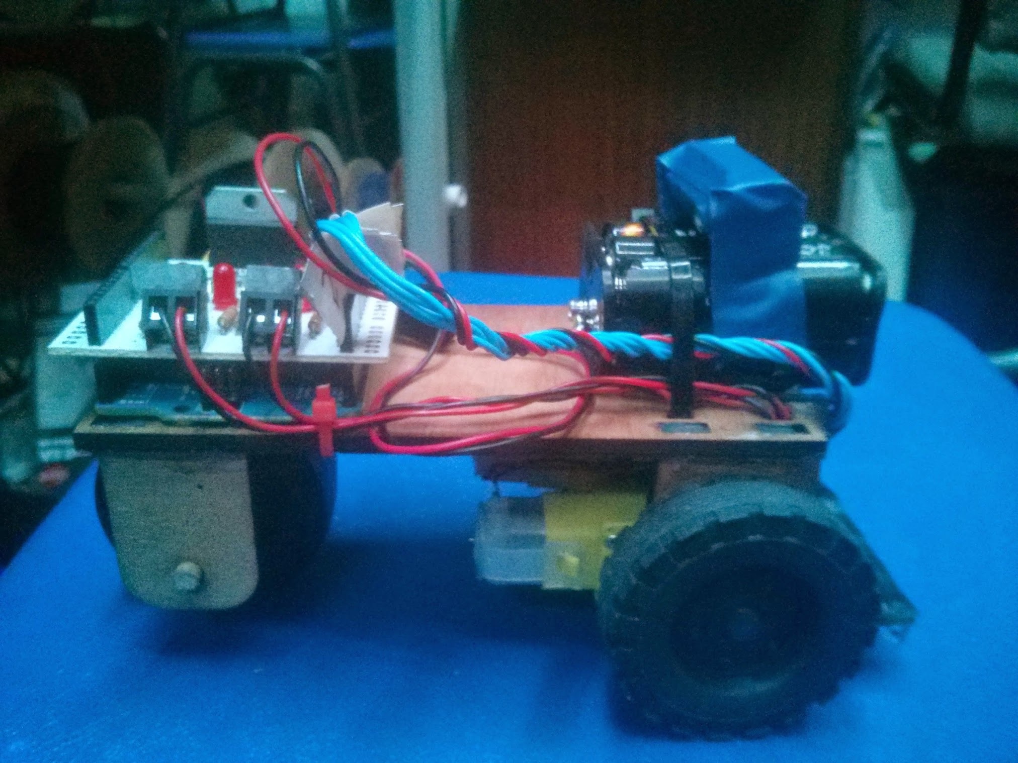
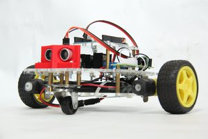
E.R.N.I.E (EARS Robotic Navigator and Intrepid Explorer) was the project I came up with for the electronic engineering project. ERNIE is a very low cost line following robot that can be assembled and programmed by students with very little previous knowledge in electronics or programming.
Over the past few years the project has evolved to become (almost) fully re-usable by only requiring zip ties, screws and electrical tape to assemble. The only part that cannot be done again is the soldering of the PCB, but the assembled PCB can of course be re-used.
The Problem:
The problem with a lot of robot kits currently available on the market is that they are either very expensive and over complicated or they are lacking in tutorials that can be used in a educational environment. Most of these robots also either come pre-assembled or are too difficult to assemble during a single class. This leads to the robots being put together once and then just handed to students pre-made, taking away from the learning experience as well as requiring more storage space.
To solve these issues the E.R.N.I.E project has the following aims:
- Simple - The E.R.N.I.E kit should be easy to put together and not have any unnecessary/complicated features.
- Cheap - The E.R.N.I.E kit should be made as affordable as possible, this is achieved by keeping the design simple and using commonly available parts.
- Reusable - The E.R.N.I.E kit should be easily disassembled so that the next student is able experience mechanical assembly as well as programming
- Educational - The E.R.N.I.E kit should come with full lesson plans/tutorials on how to construct and program it that a high school student could follow
I know that so far at least one student who did the headstart E.R.N.I.E project has gone on to study electronic engineering at the University of Surrey. My hope is that by publishing this project (and eventually selling kits via tindie) more people can become inspired to pursue STEM subjects.
The solution
To fulfill the above requirements three things need to be produced:
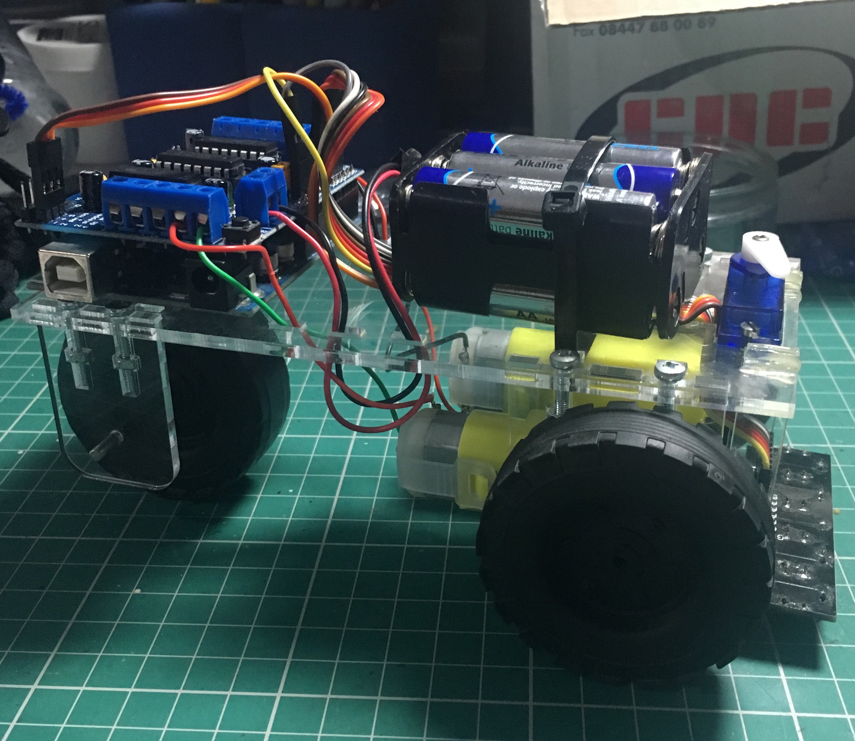
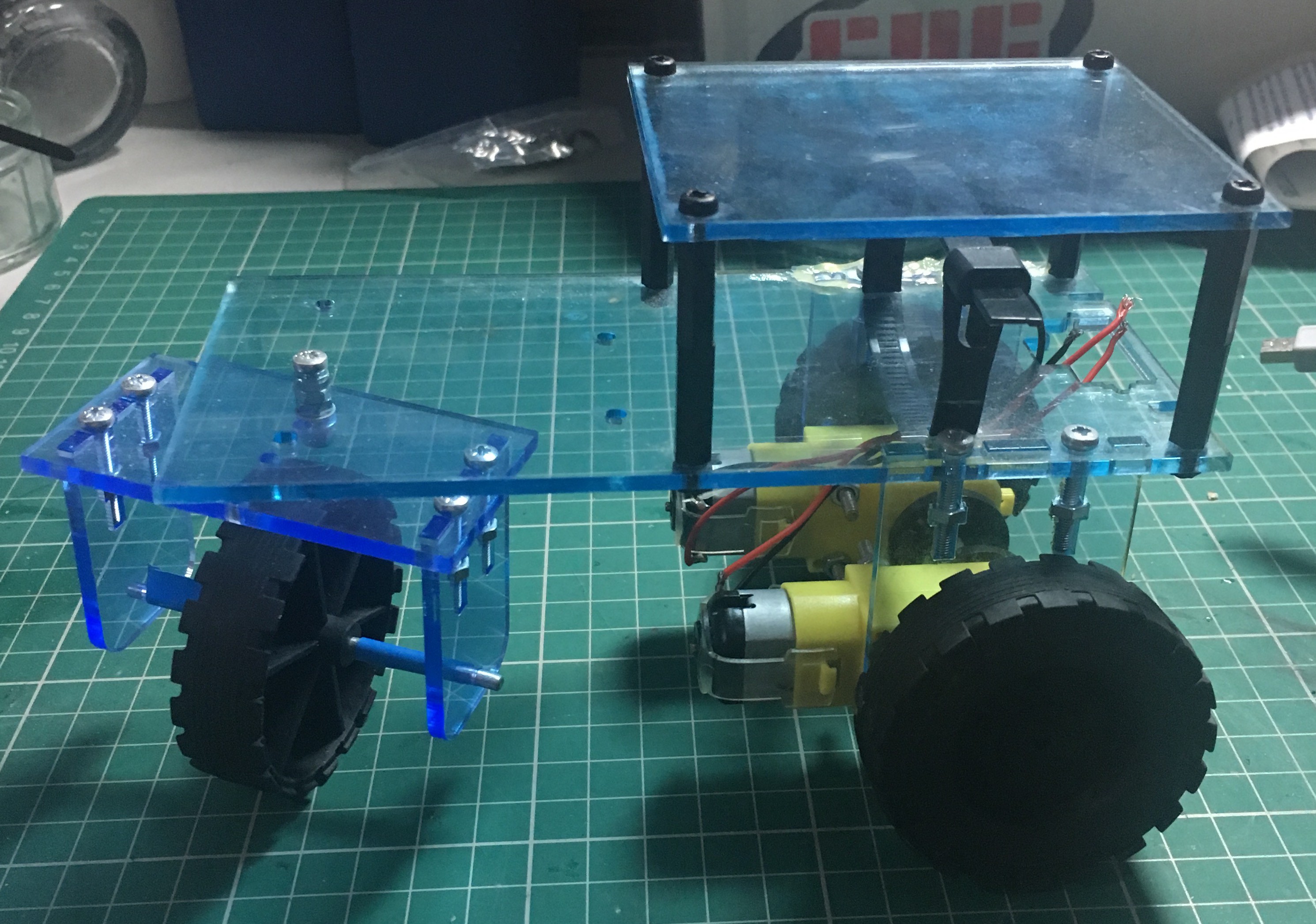
- The chassis - The E.R.N.I.E chassis is designed to be laser cut from 3mm stock (such as acrylic or plywood) and can easily be assembled using nothing other than a crosshead screwdriver and zip ties. The chassis is designed to be fully disassembled so that future classes also get the experience in mechanical assembly. If the school/club has access to a laser cutter or 3d printer a chassis can be manufactured by the students to introduce CAD/CAM software.
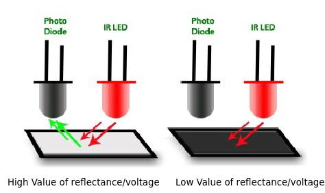
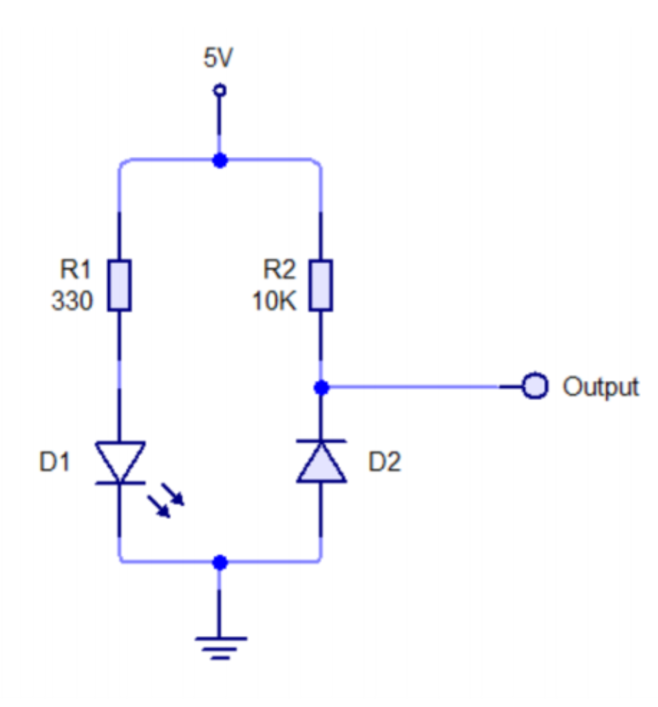
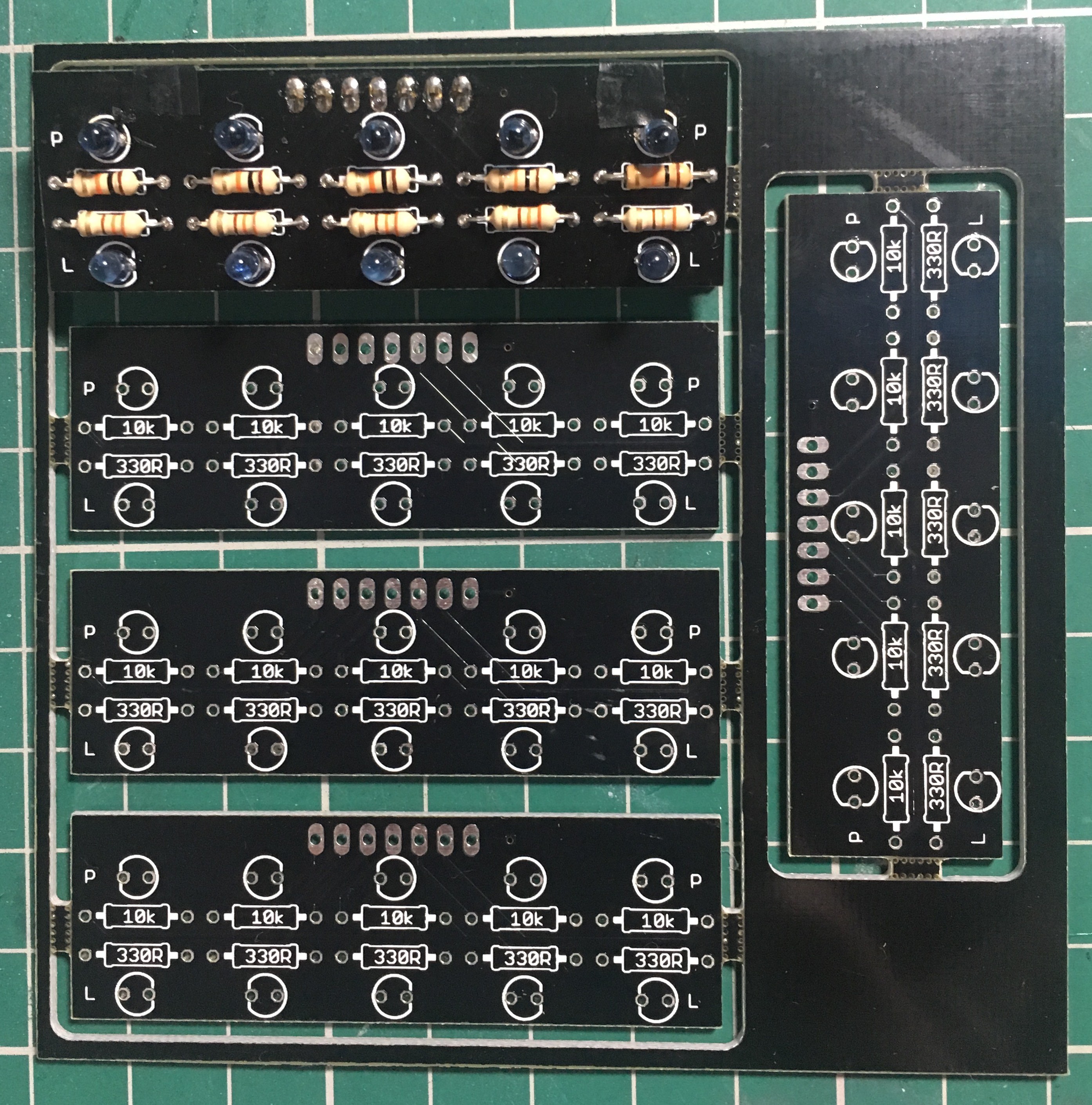
- The sensor board - In order to keep the cost low a simple IR LED and phototransistor matched pair is used to detect a line. Five of these sensors are then placed in an array. By using five sensors more complex behaviours can be programmed in the future such as stops or forks. The PCB for this sensor is designed to be clearly labeled and uses only through-hole components to make them novice friendly. Unfortunately the soldering process is difficult to undo and reuse the components like the chassis. The sensor bar costs only ~£3.50 so new sensors could be produced by each class or they can be re-used by future classes.

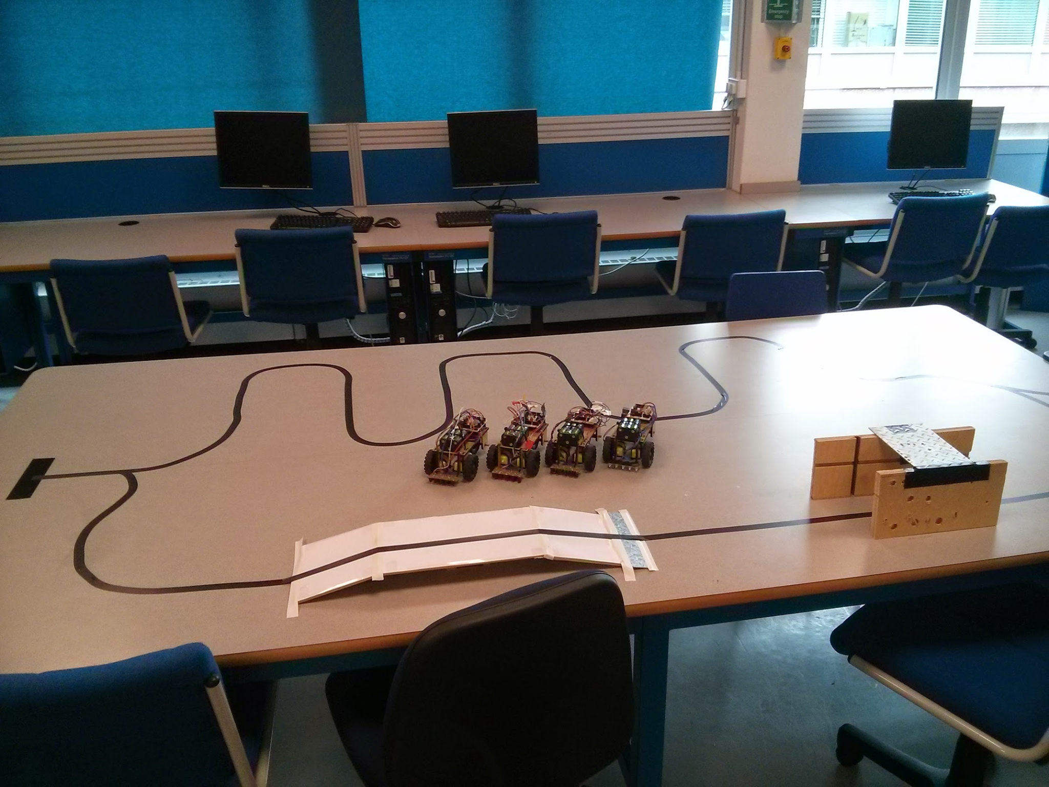
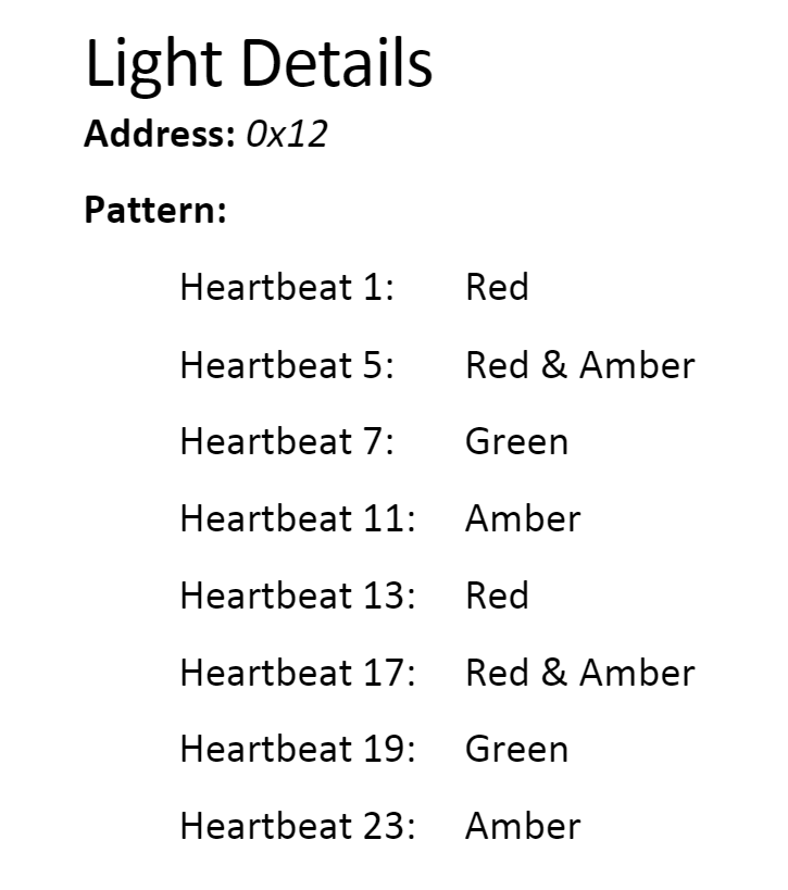
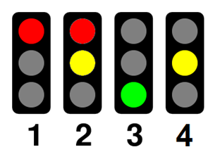
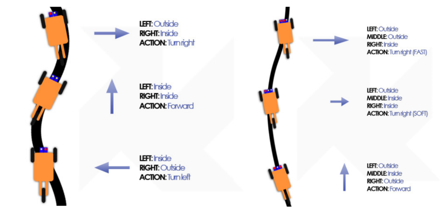
- The lesson plans - The most important part of the kit, that differentiates it from others, is the lesson plans that will come with it. Currently there is a lesson about how to program E.R.N.I.E as a simple line following robot which can be seen here. In the future lessons will be added for: A more advanced PID line following robot; Obstacle avoidance using a ultrasonic distance sensor mounted on a servo. Alongside this E.R.N.I.E is part of a class project where a complex track is...
 The idea
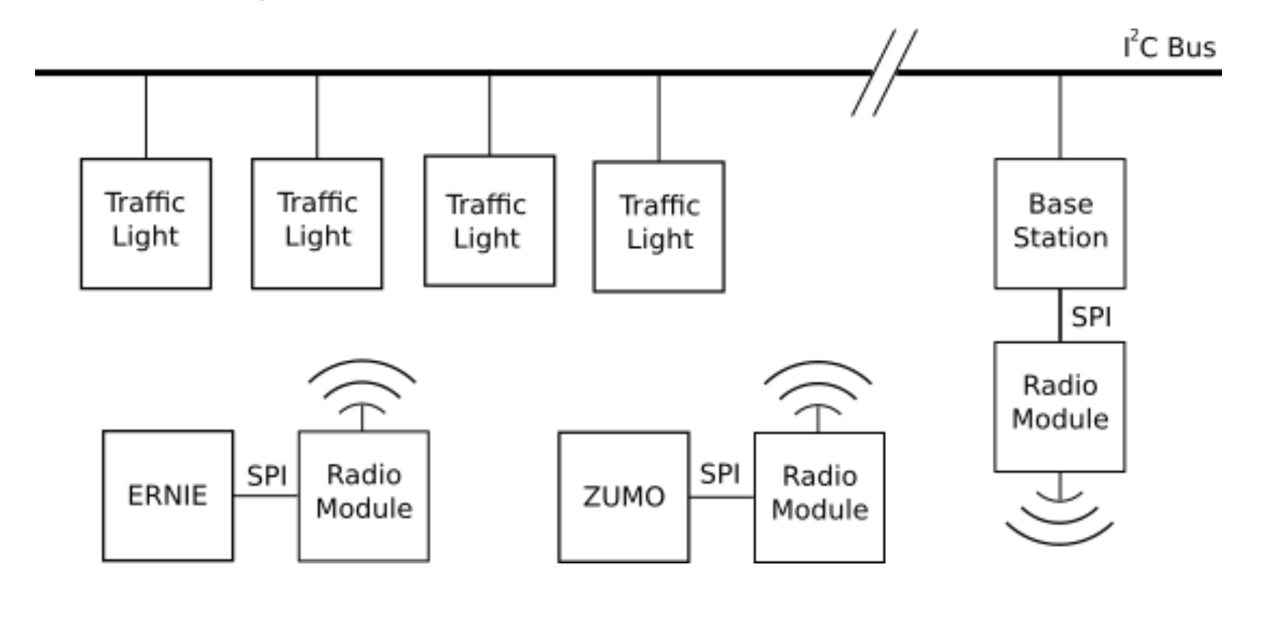
 shamylmansoor
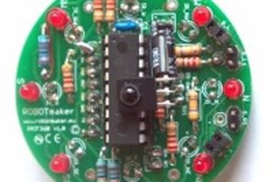
 robotmaker team
 Alexander Kirillov
 Joshua Elsdon