 Sproket
Building blocks of the project:
- Microphone amplifier
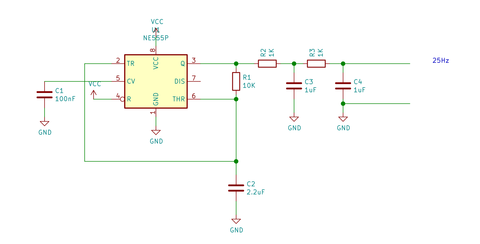
- Signal Generator - A sine wave with frequency depending on character and era (~30Hz)
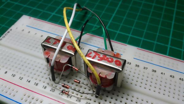
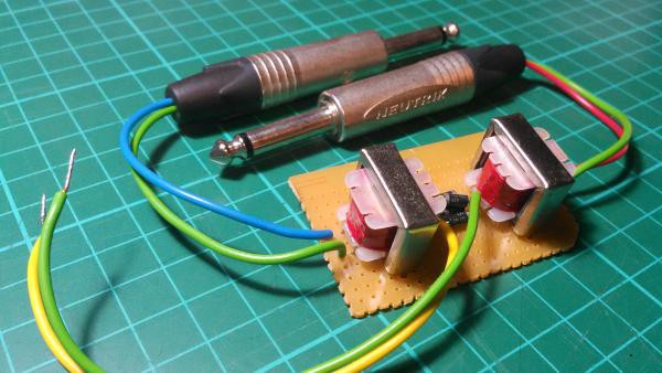
- Ring modulator - Combines a generated frequency with a voice input, making the effect.
- Output Amplifier and Speaker
- Fading light effect (Optional)


 UPDATE: using
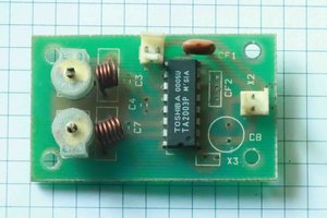
 mit41301

 Jonathan Kelly
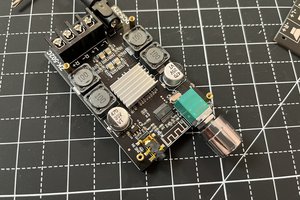
 ElectroBoy