 Pavel
PavelHere is my description of my further tinkering with TV.
So, i bought this little TV almost a year ago, dove into it for a while, threw up some "unneeded" parts (tuner, most notably) and added two wires to it, so I could feed composite signal into it. Fed some crude generated signal, saw white and black stripes and then put this project on hold. And now my interest in it reemerged, so I dug this TV up and restarted activity on it.
This time I decided to give a go for working with logic chips, as mere diode-transistor logic would be too slow for generating complex signals, so there are some fine patterns could be seen on the screen. Also, this way, the board is much more compact, has much less interconnect complexity, hence less chance of making a mistake. And works faster, yeah.
I conceived counter-based circuit for outputting blanking and sync signals for crt tv. The signals are loosely based on PAL standard, but not exactly. It supposed to be non-interlaced 50 Hz 312 line composite monochrome video. For this project 16 MHz chrystal and bunch of 74HCxx ICs are used, 10 in total.
Here is the schematic:
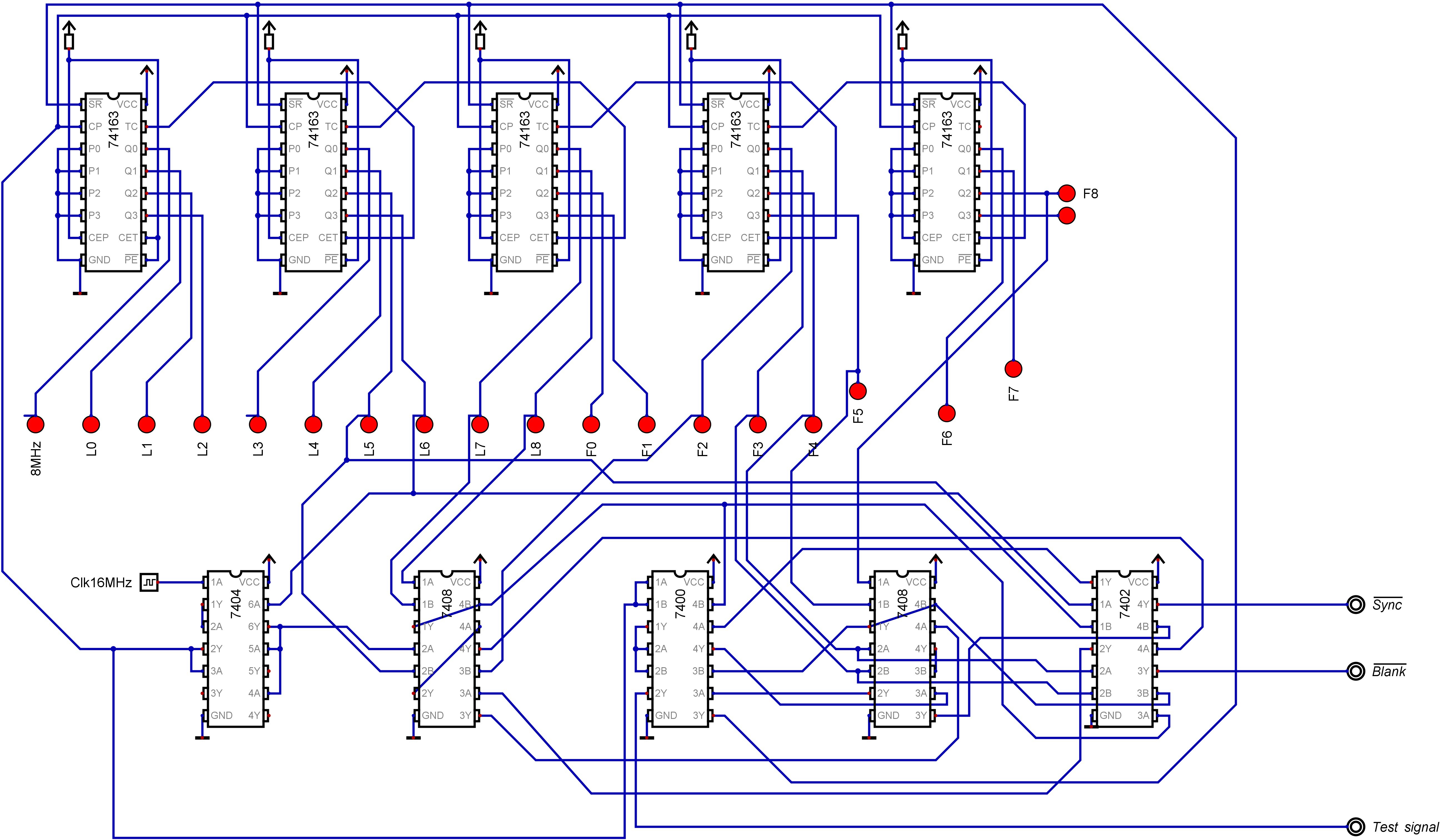
(This image is exported from Digital logic simulator made by H. Neeman https://github.com/hneemann/Digital (Logisim clone))
Base clock signal is 16 MHz, for each line there is 1024 clock cycles; for each frame there is 312 lines. Frame and line blanking intervals and sync pulses are generated by combinational logic from appropriately divided clock pulse.
Outputs L0 through L8 comprise dot counter for a line, so 512 dots (1024 clock cycles, 64 us) per line can be addressed. Among them, first 384 dots (768 clock cycles, 48 us) are used for actual image, and other 128 dots are used up for blanking interval and sync pulse (4 us blank only, next 4 us blank and sync, and last 8 us again blank only).
Outputs F0 through F8 are a line counter for a frame, counter resets at count 312, so there is 312 lines per frame, giving us 312l*64us=19,968 ms per frame, or ~50.08 frames per second (acceptable for TV). Among these 312 lines, first 288 are for image, and other 24 are for frame blank and sync (4 - blank, 4 - blank+sync, 16 - blank).
Overall frame generated looks like this:

The frame is scanned left to right, top to bottom. White color reprsents the area of image, grey is blank signal, black is blank+sync.
Here is the actual board (quite messy):
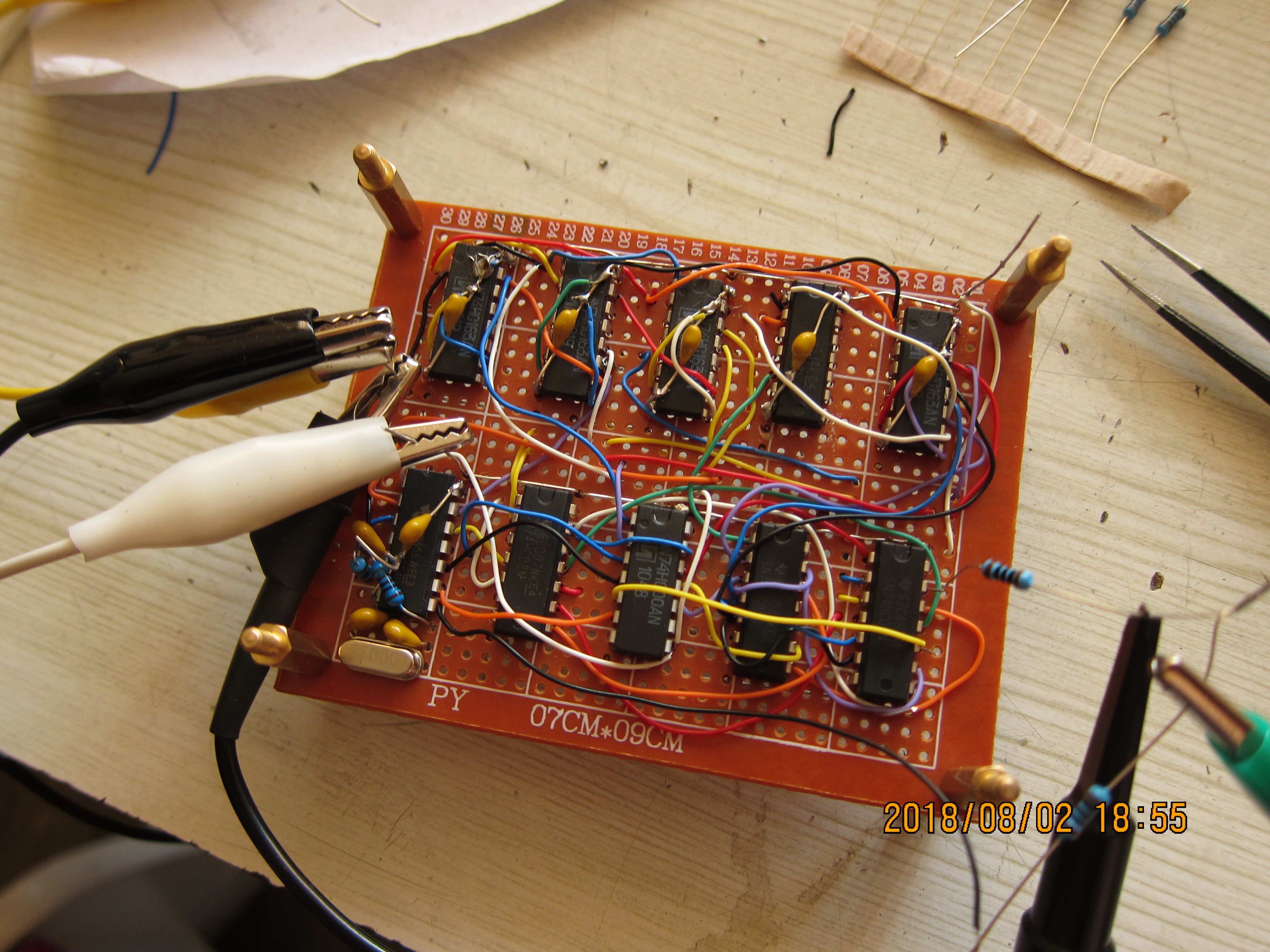
The chips are directly soldered to the board, all have capacitors between Vcc and GND (for lower row chips these caps are underneath the board). While making the board I learned a lesson about why direct solering of chips is bad practice -- I fried one of my 74hc163 synchronous counters (fourth in the top row), and had to desolder it and use ripple counter which I had instead. Test signal is also somewhat differ from schematics -- I used TC output (carry) from the first chip, and ANDed it with the third bit of line counter.
Here is oscilloscope view of the signal generated (already hooket up to TV):
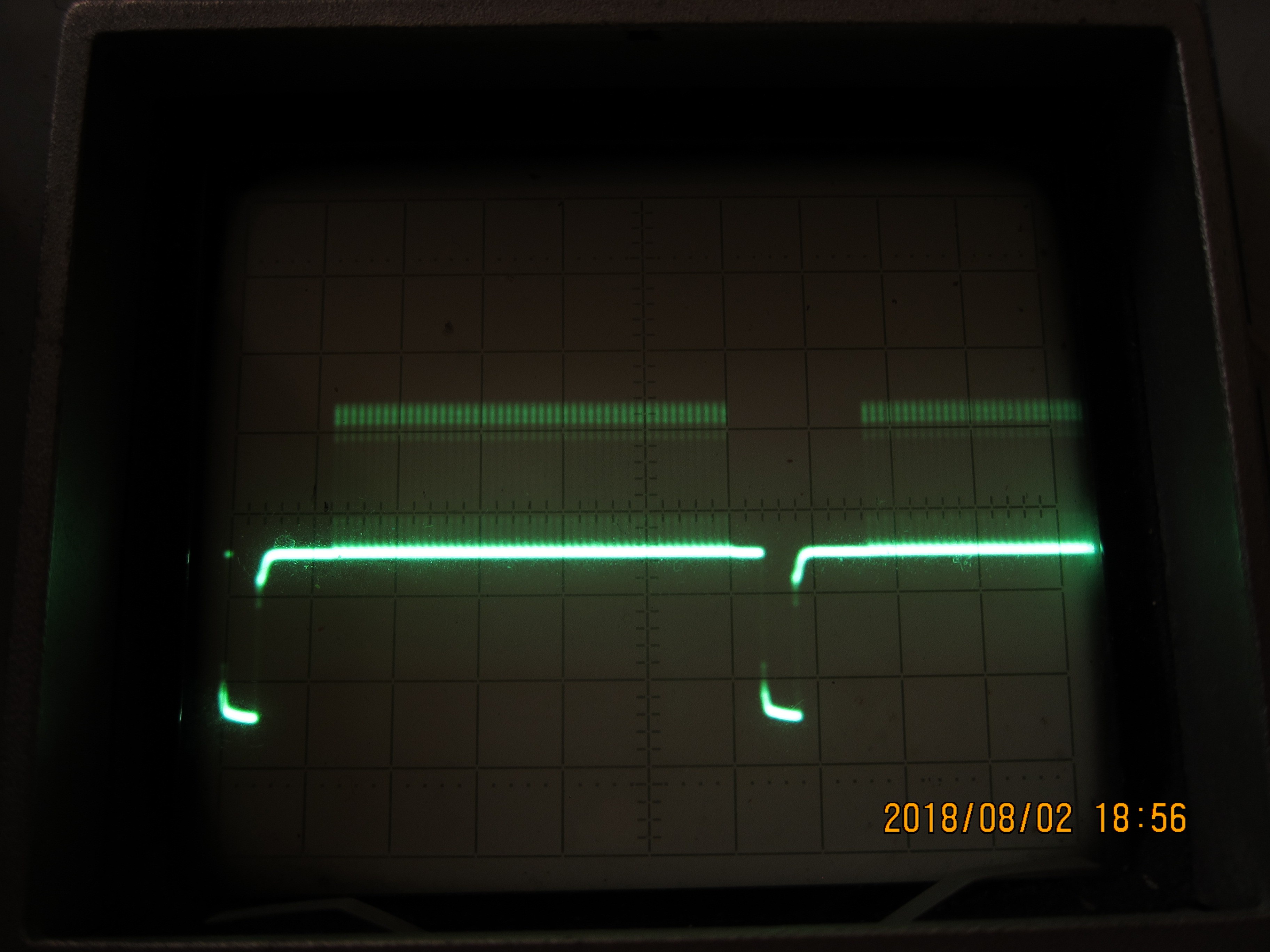
Each horisontal division is 10 microseconds, each vertical division is 1 Volt, ground is the first solid line under downward-going sync signal. The signal levels are quite not standard, but my TV can cope with it (slight tuning of brightness and contrast is all it needs for the picture to be what it supposed to be).
And, for the result is actual picture of the screen of TV fed with this signal:
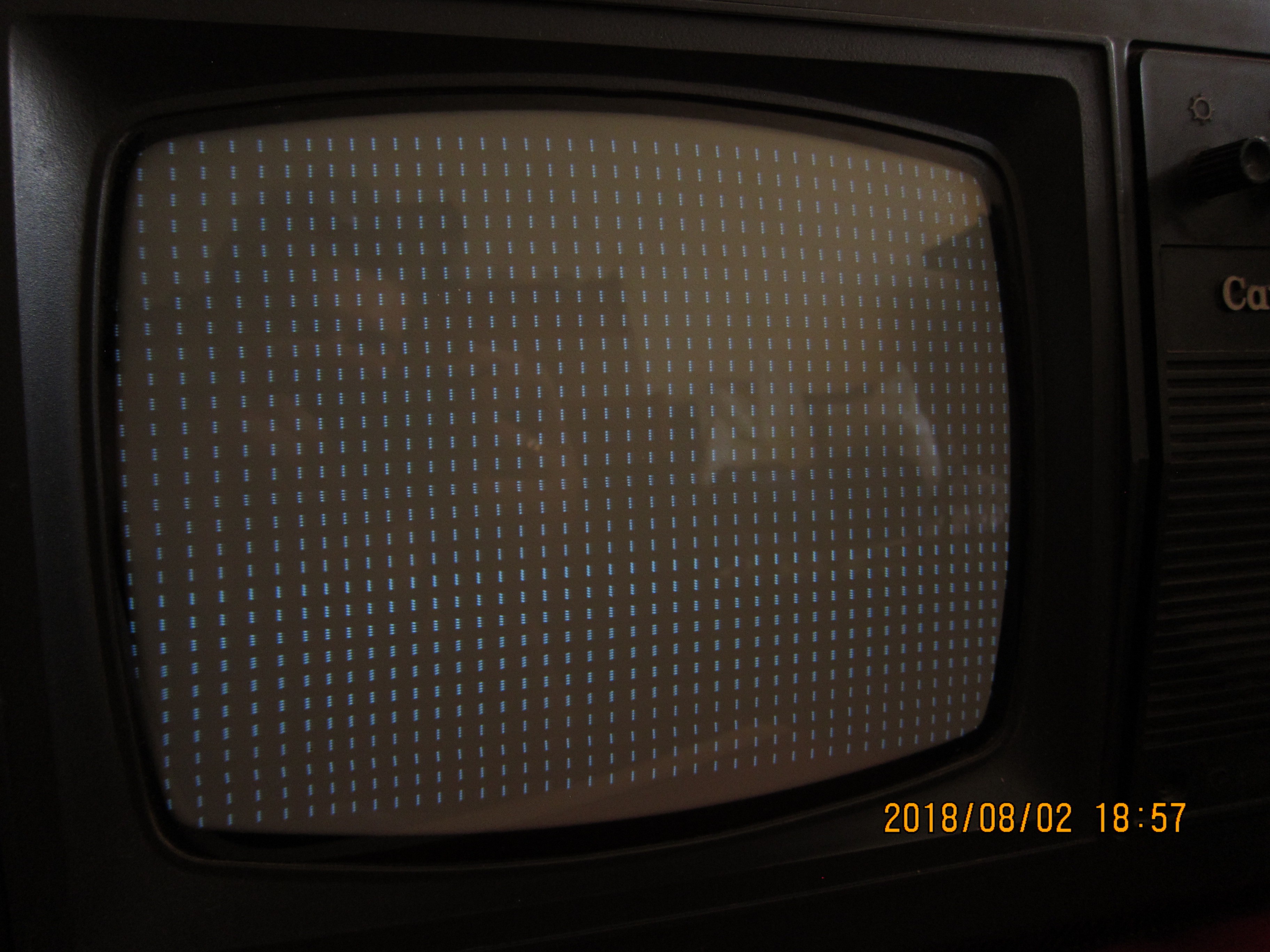
The picture looks almost like I thought it should look, overall. But there are some deviations: the horisontal resolution varies across the screen -- the distance between bars should be the same, but in actuality, in some places they are closer together, and in other the bars are further apart. It seems there are some problems with horisontal scan circuitry, it gives sawtooth signal with some interference. Also, not apparent on still photo, the picture as a whole wiggles slightly, changes size. The lines themselves are not stable and slightly tremble up and down, despite signal being fed is clean, stable and should give non-interlaced image. I think, this can be the result of the old age of the TV , which have old and low-quality USSR-made electrolite caps in it.
Second disappointment came from the fact that this TV overscans horisontally quite a lot -- there is only 41 full columns (and additional two partially seen on the very edges) of bars seen, instead supposed 48, so only 41 microseconds, or 328 dots per line, instead of hoped 388. TV's internal blanking circuits for vertical scan are also very aggressive -- there are only 29 rows of bars (or 232 lines) out of supposed 36 rows (288 lines) are seen on screen.
As a conclusion, using logics chips (74hc series) proved very appealing, and makes me wonder why I haven't used them earlier. For this application they were the only option, because diode-transistor logic gates made of discrete components can not work at these frequencies (16 Mhz). Also, especially for counter, the circuit would be very big and complex, with many possible ways for making mistakes, and will take much more time (which, as of late, I have little to spare) to construct. The TV, on the other hand proved to have much to be desired. May be for watching TV programs it would suffice, but for a kind of monitor/TVT it needs some repair.
Discussions
Become a Hackaday.io Member
Create an account to leave a comment. Already have an account? Log In.
Love this hack! Old monitors good for retrocomputing are difficult to get by, but old analog TVs (which no longer work because there is no signal in the air for them) can still be found. It would be cool to have a set of instructions and some handy circuit to bypass their tuners and use them as low res monitors :-)
Are you sure? yes | no