Close
0%
0%

Terrible Cluster

5 Raspberry PI Zeros. One custom USB hub. Endless disappointment.

Similar projects worth following
Terrible Cluster is a toy computing cluster for experimenting with distributed computing and software deployment tools. The Terrible Cluster backplane board uses USB 2.0 to tie together five Raspberry Pi Zeros in a compact package. Total cost unassembled is around $100, half of which is SD cards.

The author does not expect that this will be of any benefit to society. I mean, maaaaybe someone could learn something about cluster computing, networking, USB, or hardware design, with their very own palm sized cluster. But only as a cautionary tale.

Please keep any advice about cluster simulation with multiple VMs, dumpster diving for free PCs, alternative interconnects, complaints about Pi availability, and how I'm contributing to the decline of humanity to yourself. I don't call you out on idling your car for ten minutes in the drive through waiting to purchase overpriced coffee every morning, so please return the favor.

"If you were plowing a field, which would you rather use: Two strong oxen or 1024 chickens?" -Seymour Cray

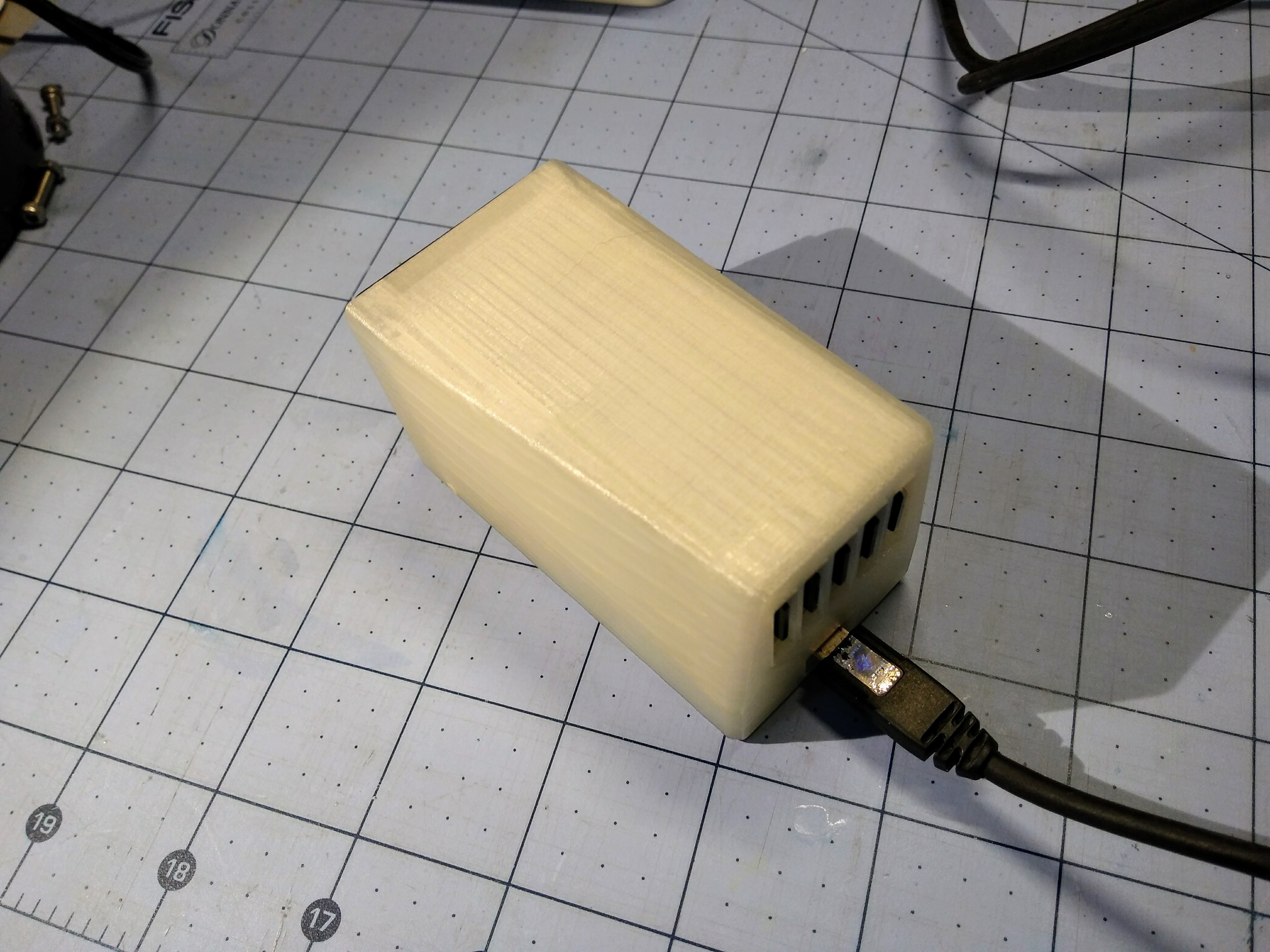
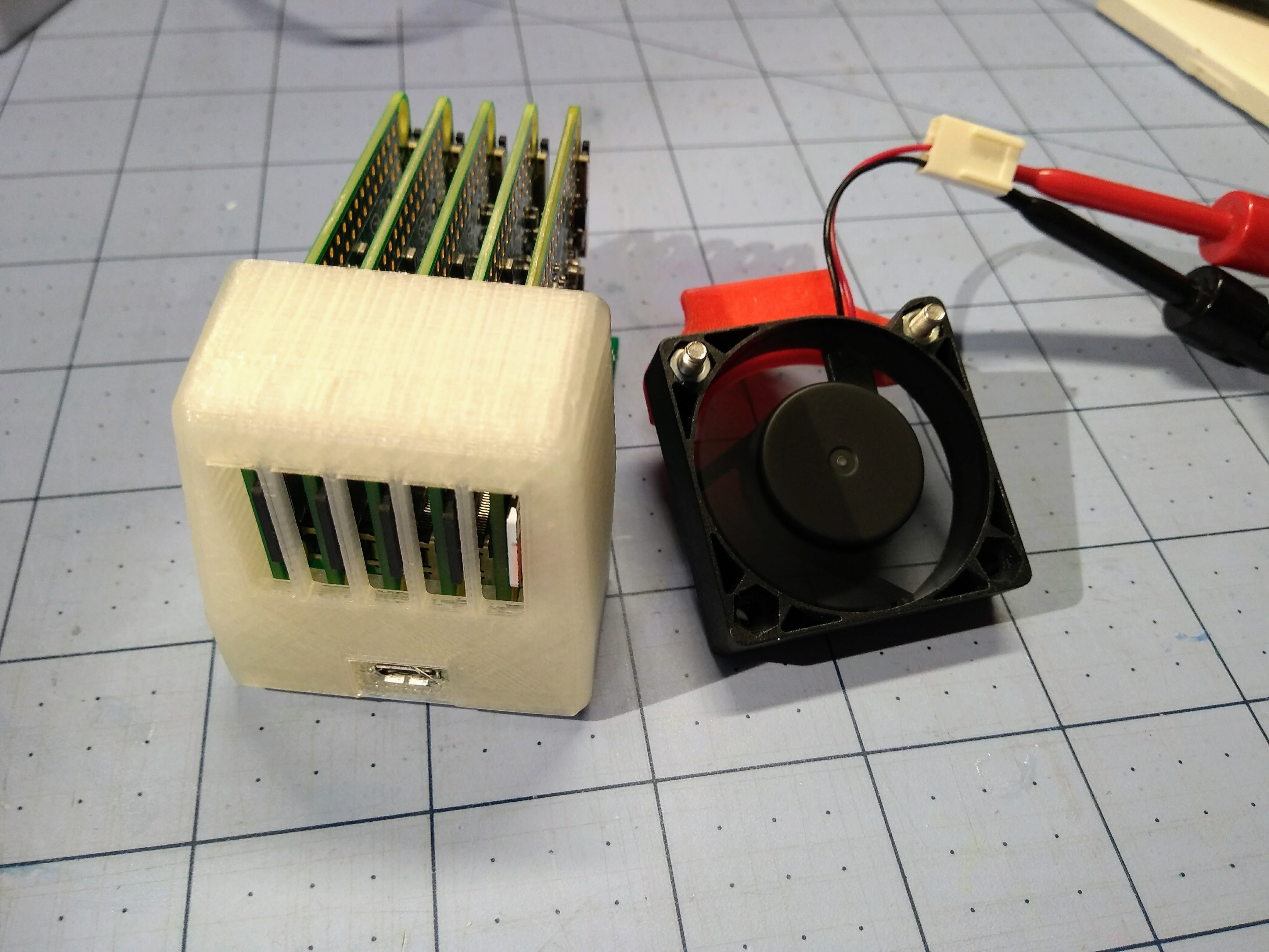
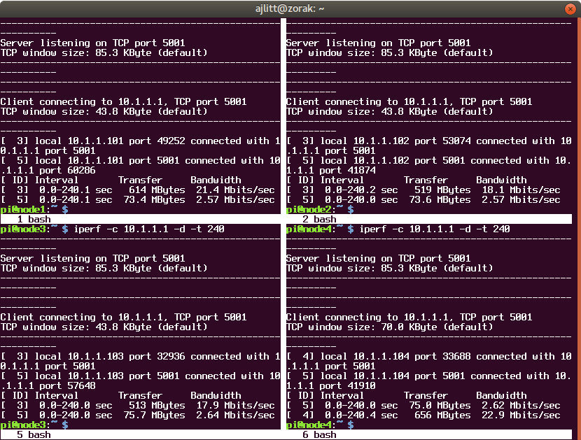
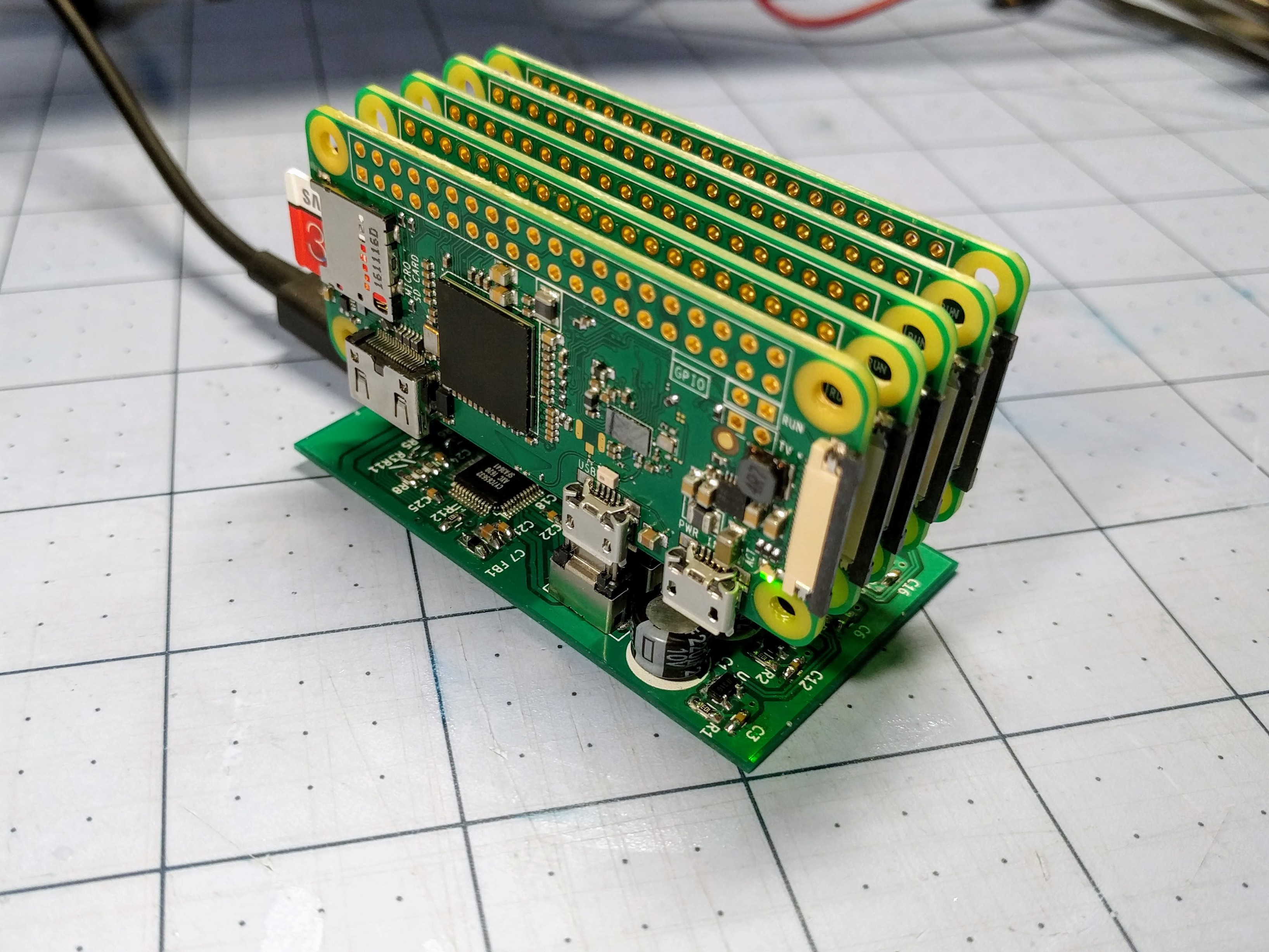
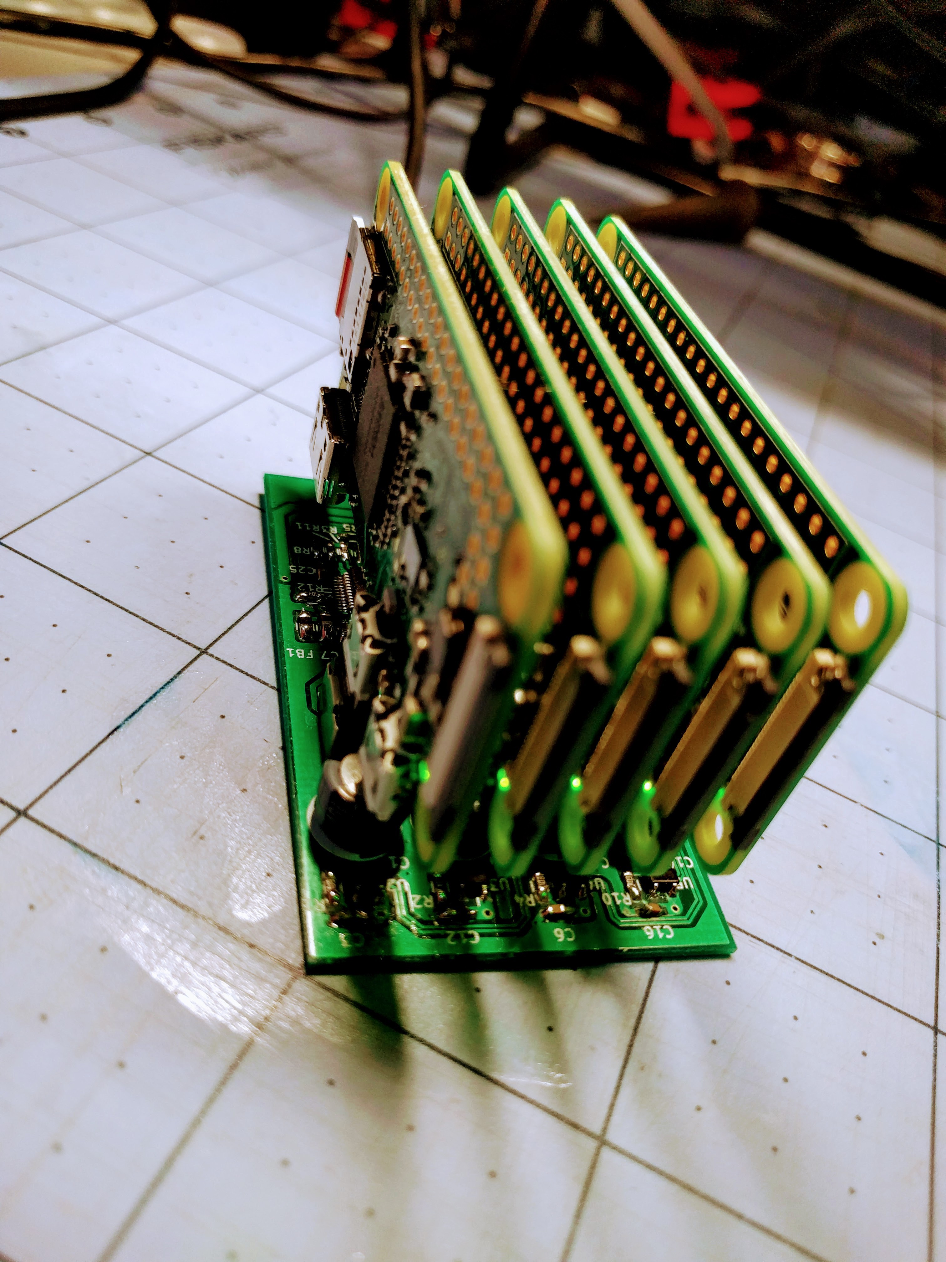
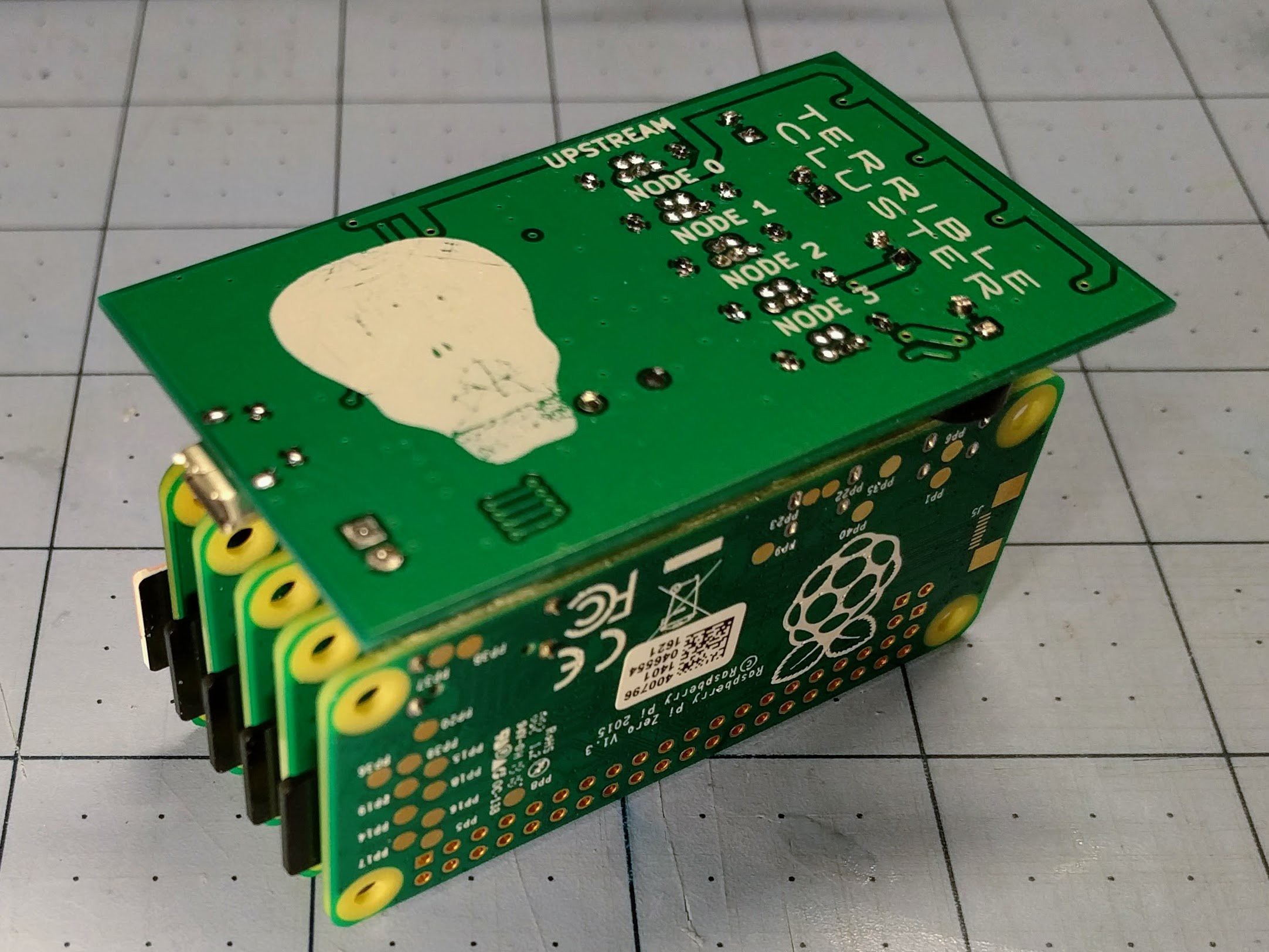
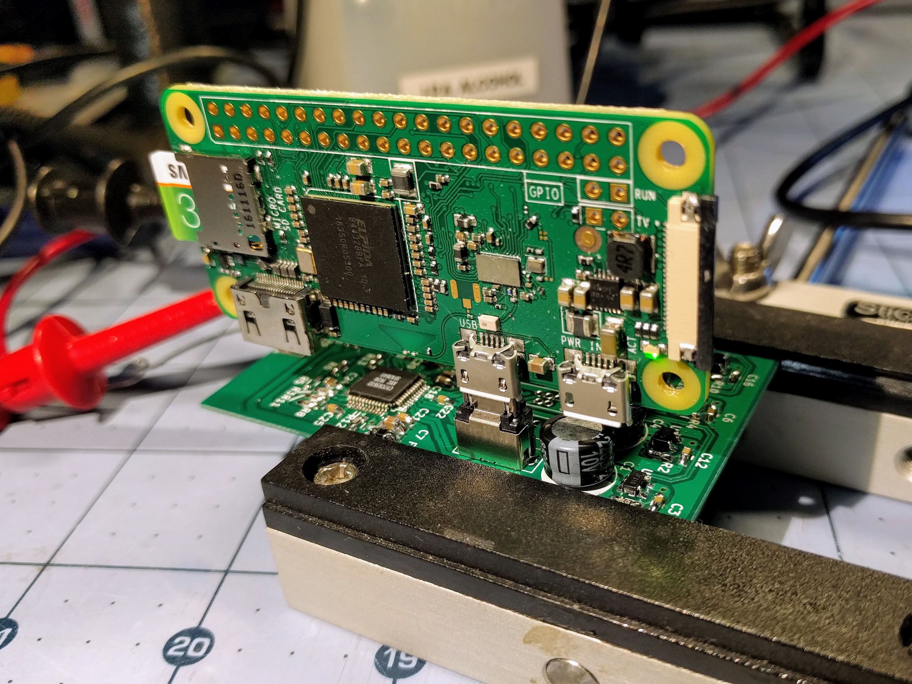
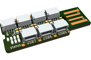
Terrible Cluster is possibly the worst example of a computing cluster imaginable.  Four Raspberry Pi Zeros each offer up their puny decade-old ARMv6 core and meager 512MB RAM for computation.  Meanwhile, a Raspberry Pi Zero W head node tries in vain to direct traffic across an inappropriately named "fabric" using USB 2.0, host a distributed filesystem, and control power to the compute nodes.  The Terrible Cluster backplane board powers and connects all five Pis together using a Cypress USB 2.0 hub and four USB power controllers.  Through hole micro USB vertical plugs allow 6mm spacing between nodes which results in a high density compact system that fits easily in the e-waste recycling bin of your local electronics retailer, under the tire of a passenger vehicle, or down the bore of an abandoned oil well.

I created Terrible Cluster to further my experience working with cluster systems and to play with strategies for cluster deployment of firmware and applications.  This hackaday.io project is a fantastic opportunity to strengthen the above self-delusion through accumulation of Internet Points in the form of views and skulls.

terrible_v1a_bom.csv

Terrible Cluster backplane BOM for DigiKey* *now with microUSB jack that fits the PCB

Comma-Separated Values - 2.74 kB - 11/12/2017 at 20:41

Download

terrible.pdf

Terrible Cluster backplane v0.1 schematic PDF plot

Adobe Portable Document Format - 83.54 kB - 10/18/2017 at 02:59

Preview
Download

terrible_v01_gerbers.zip

Terrible Cluster backplane v0.1 Gerbers

Zip Archive - 181.35 kB - 10/18/2017 at 02:58

Download

  • 1 × Raspberry Pi Zero W Head node and WiFi network gateway
  • 4 × Raspberry Pi Zero Compute node, may be 1.3 or 1.2
  • 4 × Diodes Inc. AP2191DWG 1.5A USB power switch
  • 1 × Sunon fan MF40100V2-1000U-A99 Required if using case, 5V 40x40x10 fan, 7.0CFM, 20.6dBA
  • 1 × Terrible PCB See the github in the sidebar. KiCad project, pcb v0.1 Gerbers, and PDF schematic are there

View all 12 components

  • Of big hammers and putting them down

    ajlitt10/24/2017 at 19:09 4 comments

    In the last update, I found that the Raspberry Pi USB device boot doesn't like waiting, and with some small changes to usbboot was able to prevent any of the nodes from timing out when powered up all at the same time.

    Now there's another problem: at random, usbboot fails to send the first stage "bootcode.bin" to the Pi Zero, which causes all future transfers to that Zero to fail until it's power cycled.  I spent a couple of late nights trying to figure this out.  Is it because the ROM bootloader has some other timing constraint (not sure)?  Is there a signal integrity or power problem with my board (maybe)?  Are the hub ports going into a low power mode, angering the ROM bootloader (nope)?

    The only thing I'm sure of that fixes it is a power cycle.

    So in the spirit of inelegance that defines this project, I modified usbboot to cycle power on any slot that fails on a transaction involving bootcode.bin. 

    And it's not that inelegant either.  Because I'm using the USB standard for in-band power control of hub ports, I can traverse up the USB tree from the current Pi's USB device that failed to find the hub.  Once I have a handle for the hub, I send a message to the hub requesting that power be turned off and on to the Pi's port.  When the Pi resets, it re-enumerates on the USB bus and is detected again by usbboot.

  • Improved terribleness

    ajlitt10/22/2017 at 18:53 0 comments

    The problems that I saw with usbboot seem to be a result of not being designed for booting multiple targets at once.  rpiboot would end up serving bootcode.bin to all of the nodes at once, then serve the complete set of files to each node one at a time until no more Broadcom ROM boot devices are found on the bus.  This would be fine, except that the Pi seems to hang after a certain amount of time after sending bootcode.bin if the transfers haven't completed.  Since the failing node seems to die in the middle of a file transfer, I suspect that it's a watchdog timer or maybe a bug in one of the binaries involved in boot (bootcode.bin or start_cd.elf).

    Whatever the root cause, it goes away as long as usbboot services only one node at a time.  I came up with a fix that prevents rpiboot from talking to any other Broadcom devices in USB boot mode until it has finished booting the current device.  Once it sends bootcode.bin successfully to one device, it will ignore other devices when scanning for the second stage boot device until it has completed serving files to the current device.  A timeout prevents it from hanging indefinitely in the case where the current device fails to re-enumerate after bootcode.bin is sent.

    I think I have it working reliably now, but it will take some overnight testing to prove it works.

    A better solution, perhaps for the future, would be to make usbboot multithreaded, spawning a handler thread for each ROM boot target.  This should be straightforward since the USB IDs are different for a Pi waiting for bootcode.bin (2763) and one that is re-enumerated after bootcode.bin executes (2764).  This should also speed up the boot process.

  • Terribly unreliable

    ajlitt10/20/2017 at 20:08 0 comments

    One problem that's plagued the project is the USB boot process.  The fourth node almost always fails to boot on the first try.

    Terrible Cluster relies on the rpiboot utility from the Raspberry Pi Foundation to serve the bootloader and kernel to each of the compute nodes.  rpiboot first watches for a USB device to be plugged in matching a Zero in USB device boot mode.  It then sends down the first stage bootloader "bootcode.bin".  The first stage begins executing, recognizes that it was booted from USB, and the reinitializes the USB controller in device mode.  rpiboot notices that the device has re-enumerated under a different device ID, then it enters a USB fileserver mode.

    At this point, bootcode.bin goes through the same process of loading executables and config files as when booting from an SD card: start_cd.elf, config.txt, kernel.img, etc.  But instead of fetching the files from SD, it requests them from the USB host.  rpiboot sits in a loop waiting for file requests and sending files to the device until it receives a message saying that the device is done, or a transaction with the device fails.

    This works fine for me when I'm booting one Pi at a time.  However, when I am booting all four Pi Zero nodes at once it often fails when sending the kernel to the fourth node that it boots.  rpiboot does not operate sequentially, instead sending bootcode.bin to first USB device with a matching bootloader VEN/DEV.  It is always the fourth one that fails, and it does not appear to favor a particular slot.  Once a node finishes loading all of the required files over USB, it boots reliably.  So this has everything to do with the USB boot process, and not the OS.

    If I can't trust rpiboot to sit in the background and serve files to booting nodes, then this isn't going to be a useful system for learning about software deployment.  Sounds like a good debugging project for the weekend...

  • Many OpenSCAD lines later...

    ajlitt10/19/2017 at 06:21 0 comments

  • Hot mess

    ajlitt10/18/2017 at 06:22 0 comments

    After a truly terrible week of meatspace problems last week, I'm back.

    I've been working on and off on a 3D printed case for the cluster.  The case doesn't need to be beautiful, but it does need to protect the cluster and restrain the Zeros so they don't flop around on the backplane's USB headers.

    One problem though: the HPL runs from earlier show that the CPUs can reach over 70 degrees under load in ambient air.  In an enclosure it's going to be much higher even with vents for convective airflow, and PLA plastic starts getting soft around 65 degrees...

    Thus a fan is going into the case somehow.

    Enjoy this pic of a test fit print while I figure this out:

  • Less terrible

    ajlitt10/04/2017 at 04:07 2 comments

    Although performance is not the goal here, I wasn't happy that the cluster wasn't benching anywhere near what I expected with HPL.  After some head scratching, I found out that the math library that I used to build the benchmark (libatlas) is built for soft-float in the RPi repos.

    I rebuilt HPL with the libopenblas math library, added the head node into the pool, and hooked up my bench supply so I can use its current meter.

    Now the terrible cluster does a max of 1.281 GFLOPS, and drew an average of 4.962W over the run.  That means it's only 72 million times slower than the fastest computer on the June '17 Top500, and at an efficiency of .258 GFLOPS/W is 4.9 times more efficent than the least efficient computer in the same list.

    (corrected with a slightly higher score after retesting 10/5/17)

  • Terrible metrics

    ajlitt10/02/2017 at 21:46 0 comments

    Following instructions found here, I ran the HPL benchmark on the four compute nodes of the cluster.  On the first try, I'm getting 390MFLOPS.

    That's 300 million times slower than the fastest ranked supercomputer as of June 2017.

    However, it's at worst only 40% less efficient* than the least power efficient computer on the same list, so that's nice I guess.

    *Didn't measure average power during the run, but it does have a 5V 2A power supply and isn't hitting the limits.  So I'm assuming 10W running full out.

  • Clusterstuck

    ajlitt09/28/2017 at 02:42 4 comments

    I spent the last couple of weeks trying to figure out the best way to deploy an OS to the nodes over USB.  I spent a few late nights trying to roll my own minimal Raspbian with debootstrap, and a few more scratching my head over how to use the USB boot and an initramfs to write the SD card on first boot or when directed to reformat and reinstall.  And I was hesitant to write anything to automate any of this, since I have my heart set on using Ansible for deployment and I'm still an Ansible noob.  I was busy yak shaving and yet I still didn't have a working way to copy an OS out to all the nodes over USB.

    And then I remembered what I named this project.

    So I went for the easy way out.  Stick with the stock Raspbian Lite image.  Modify the image so that it doesn't boot over SD and falls back on USB.  Use the mass storage mode in rpiboot to write the Raspbian SD image to each node.  Use rpiboot to serve different cmdline.txt bootfiles based on the USB hub port so that they each get their own unique USB networking MAC address.  And use shell scripts for image generation and SD writing instead of making this another Ansible lesson.  None of this is how I'd imagined it working, but at least it's working now.  Later I can move the process to Ansible and different OS images and deployment schemes.

    Three evenings later and the cluster can now write a Raspbian .img to all four nodes very slowly (30 minutes or so for all 4), boot them very slowly with a unique MAC and IP (about 5 minutes for all to come up), and take remote SSH logins from the host Pi.

    It's hard (and boring) to show any of this in action, so here's a session showing a network between the head node and all compute nodes at once:


    See?  The Terrible Cluster lives up to its name.

  • Boring bring-up pt. 2

    ajlitt09/17/2017 at 05:37 0 comments

    I soldered the rest of the board. Realized I had ordered the wrong part for the USB power connector and bodged it on anyway.  I'll update on functionality in a few days.

    But for now, enjoy some photos of the assembled board and 5 Pi Zeros:

  • Boring bring-up pt. 1

    ajlitt09/14/2017 at 05:59 0 comments

    The boards came in today, so naturally I had to get soldering despite being tired from working late last night.


    I populated everything but the USB power jack and the four downstream node USB plugs.  I didn't want to waste the connectors until I checked out the upstream end of the hub.

    I first smoke tested the board with my bench PSU and checked that the oscillator was doing its thing.  Once satisfied that I didn't have any surprise dead shorts, I hooked it to my PC through a micro USB jack to USB-A plug cable going to an intermediate sacrificial hub.  I was able to see the hub enumerate under Linux, and checked that it's reporting as having per-port power control.


    I also did a test fit of a Pi Zero W, and since I'm now confident it's not going to do any damage I powered it up.  The Pi's LED did its blinking thing as usual as Linux boots.

    Stuff I learned:

    1.  The hole dimensions for the USB vertical plug are too big to fit snugly.  I had to "justify" the upstream plug with one edge of the board.  I'll need to remember to align the other four the same way to keep the Zeros spaced uniformly.
    2. The Cypress hub IC shuts off the 12MHz oscillator when nothing interesting is happening, probably to save power.  I didn't catch this detail in the datasheet.  I spent a good half hour wondering why I'd see a fleeting 12MHz on the scope on power-on and nothing afterwards.  I suspect it will stay on once I get downstream devices connected.
    3. My thermal reliefs aren't that relieving.  I soldered in one of the electrolytics backwards, and it was a pain to desolder and clean the hole on the grounded leg.  I should have used thinner spokes on the reliefs, and made sure that there was no additional ground traces hiding under the plane fill.  It would also help if I replaced the solder sucker I broke a few years ago.
    4. Just because silkscreen art looks good in the KiCAD 3d render doesn't mean it will look the same on a finished board.  For grins I converted a photo of a picture one of my kids drew in school to a KiCAD symbol.  What was supposed to be a skull looks more like an upside down diseased pear.  Elecrow and other PCB manufacturers have a resolution limit to their silkscreen.

    Next I need to get the rest of the connectors in, test downstream power control, make up a test cable for the downstream ports (more later), and maybe plug in some more Zeros.  But that will have to wait for the weekend.

View all 11 project logs

  • 1
    Get a board

    Order the PCB from the KiCad project from your board house of choice.  The board must be 0.8mm thick.  Standard 1.6mm is too thick to fit the microUSB A plugs.  I was able to get 5 boards from Elecrow for under $10USD shipped in a little over two weeks.

  • 2
    Get some parts

    Use the BOM in the "Files" section in this project to order parts.


    The BOM is a CSV direct from DigiKey and should import through their "Upload to Cart" thingy.  You might want to tweak the quantities since some of the discretes and the power switches are significantly cheaper if you go up to 10x or 100x.  Worst-case cost for parts to build a single backplane is about $16USD.

  • 3
    Solder all the things

    Solder the board according to the KiCad design.  Start with the discretes and ICs, then the vertical USB A plugs and through hole caps, then the microUSB B.

    Be very careful with the vertical microUSB A plugs as they're very touchy.  Flux the pins and the pads on the solder side of the board first.  Then once you fit each plug, force it to one side of the footprint to align it before tacking it down (first board rev only, where the holes are just a little too big for the part used).  Use the frame pins to tack the connector into alignment, since the signal pins tend to be fragile.  Once aligned, solder the frame pins thoroughly so solder wicks up the component side for mechanical stability.  This might require additional heat.  Once the frame is soldered, solder the signal pins at standard temp, but allow time for solder to wick up the hole.

View all 7 instructions

Enjoy this project?

Share

Discussions

Ale o co chodzi wrote 11/29/2023 at 20:58 point

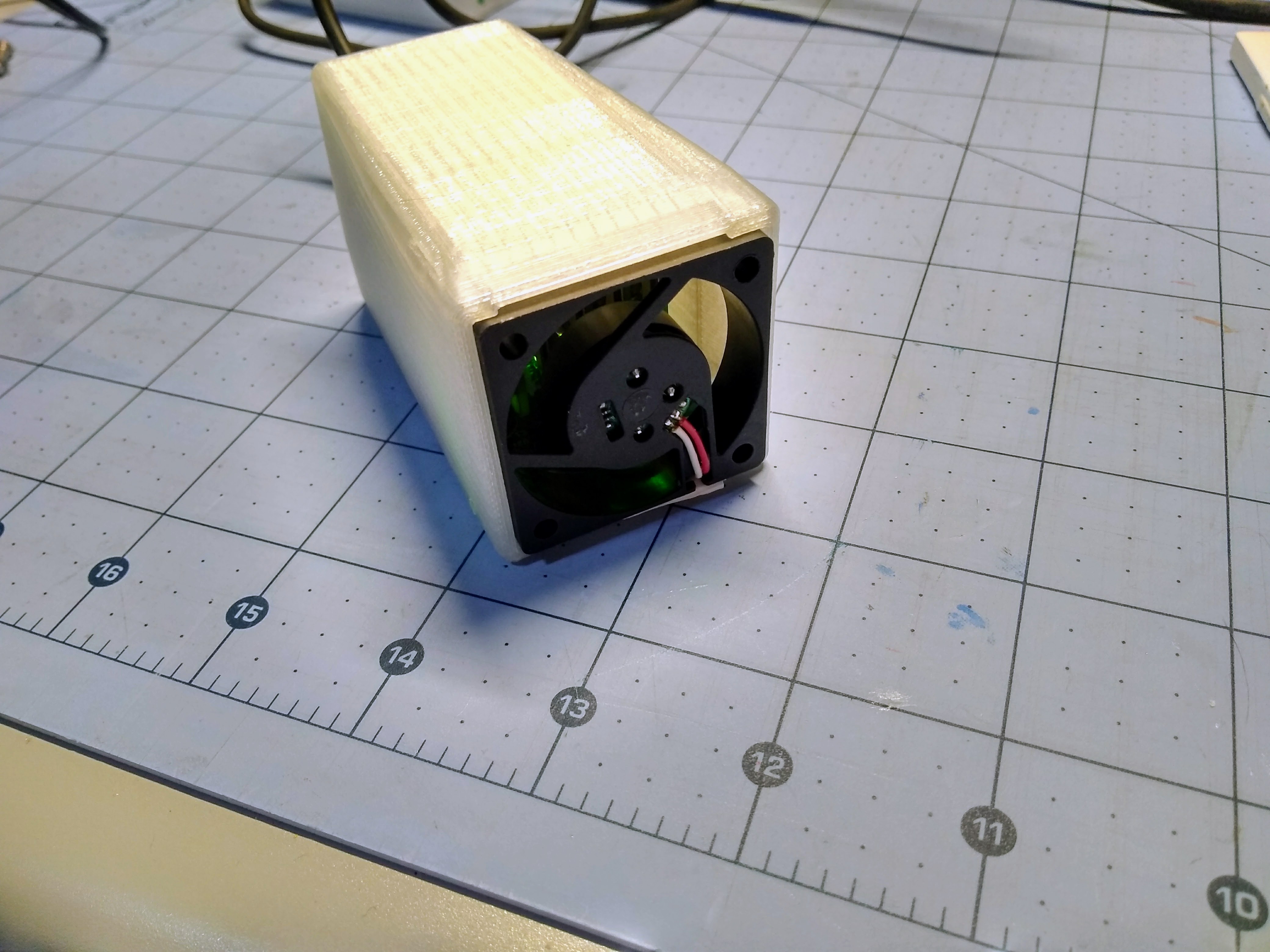
why not make a chimney layout?

high chimney and 4 nodes on walls 

rectangles , empty inside and on walls nodes , heat air go from bootom to top

  Are you sure? yes | no

crun wrote 01/01/2023 at 20:13 point

It is difficult to have even a shred of hope that the edifice of western civilisation can survive this project. It was already tottering, but this is the final straw. If only you had waited for the USB-D connector.

  Are you sure? yes | no

ajlitt wrote 01/04/2023 at 18:59 point

It'll always be micro-B with big fat PTH stakes just to annoy the "buT MiNi-uSb iS MOre mEchaNiCAlLy stABle ThaN mIcrO" crowd.

Also it's like 5 years later and I can get a nice car for what all those Pi Zeros go for on eBay.

  Are you sure? yes | no

crun wrote 01/11/2023 at 21:50 point

Can you use it to mine Pi NFTs and get filthy rich in the Bahamas?

Actually just looking at making a multi-channel remote SDR, and strangely enough, this would probably be pretty good for it, because there seem to be reliability issues with N usb receivers into one pc.

Especially if it was immersion cooled in oil - mostly to keep water and bugs out

  Are you sure? yes | no

Roger wrote 08/25/2019 at 19:55 point

This is an awesome project!  My gut reaction is kind of centered around the Communication speeds through the USB ports... and as you have mentioned, the timing issues with USB during Boot-up...  My own solution is to use a PI 2/3/3+ as the 5th Pi... and utilizing the USB gadget abilities of the Pi0. I program the 0's to act like a USB Ethernet devices... when they boot up and connect to the Pi2/3/3+, everything links right up...  I have experimented with Static and DHCP settings with the same results...  oh yeah... I forgot to mention... this eliminates the need for an external USB HUB as you are using the built in USB ports of the Pi 2/3/3+ to connect the Pi0's direct to the 5th Pi 2/3/3+

Thanks for Sharing!

  Are you sure? yes | no

sunk818 wrote 10/03/2018 at 17:34 point

I like this project. That's cool you were able to build a PCB for clustering.

I've only seen something like this -- https://www.hardkernel.com/main/products/prdt_info.php?g_code=G150152508314 

Been looking at compact cluster for crunching for distributed computing using Android ARM using low watts.

  Are you sure? yes | no

Greg Kennedy wrote 02/26/2018 at 15:46 point

Instead of the Pi Zero W and backplane, could you use a full sized Raspberry Pi B+ / 2 / 3 instead?  You have four dedicated USB ports on the B+, and you still have an Ethernet jack left.  The B+ is then also serving as a node <-> node router.  Look ma, no Cypress!

Of course, it's not as compact and pretty that way.

I am still confused as to how you "network" (route packets) over USB 2.0 without any usb-to-Ethernet adapters.  There's some kind of fundamental tech acronym thing I'm missing here.

  Are you sure? yes | no

ajlitt wrote 02/26/2018 at 16:40 point

You could do that.  I thought about a resistor pop option that would route the upstream USB port to the power jack, so a PC or another Pi could be used as a head node.  I'm not planning on another rev so it's an exercise to the reader.  There's always the Cluster Hat, which uses a Pi3 as a host and a separate control path for slot power.  Or buy a USB hub that's supported by uhubctl for per-port power control and make a wiry mess on your bench.


The networking takes advantage of the USB OTG modes on the Raspberry Pi Zero.  It makes the USB port act like a USB device (peripheral) instead of a host.  The compute nodes have a parameter in the config.txt (dtoverlay=dwc2) that tells the Linux kernel to start the USB driver in device mode instead of host.  Then the kernel command line has a parameter that starts the USB gadget RNDIS network driver on the port.  RNDIS is a virtual Ethernet interface over USB device driver created by Microsoft for Windows CE PDAs, so it has almost universal support in modern OSes.  Since I have unique boot time config files for each node, I assign a fixed MAC address indexed by slot number to each node's RNDIS interface.

There are some Linux network-manager configs on the head node that bridge all four virtual Ethernet networks into a single subnet and set up NAT so they can talk upstream over the single connection through the head node's WiFi.  I set up DHCPd and the hosts file to map the slot MAC addresses to fixed IPs and hostnames so that we can address each slot by the same name even if I shuffle Zeros around.

In theory, this is a terrible (get it?) way to cluster since the head node has to spin CPU cycles to act as a switch for the RNDIS-USB interfaces.  That's on top of the CPU overhead of the USB-RNDIS drivers and the limited horsepower of the Pi Zero CPU.  USB-Ethernet pushes some of the protocol work on the USB adapter, and an external Ethernet switch takes the packet routing stress off of the head node.

However, the BOM cost of the backplane I built is much lower than five USB-Ethernet adapters plus a switch, and it's far more compact and power efficient.  The tradeoff for USB's overhead is worth it since the Zero's CPU is relatively weak and doesn't present as big a bottleneck as with a higher performance node with more memory.

If I had to build a higher end custom cluster and had to use the Pi line of SBCs, Pi3 and an Ethernet switch is going to be the best option.

  Are you sure? yes | no

ia wrote 10/25/2017 at 19:20 point

epiphany is cheaper and less power consumptions.

https://www.parallella.org/

  Are you sure? yes | no

ajlitt wrote 10/28/2017 at 00:28 point

Epiphany is effectively a dead product.  Unfortunately there aren't any MPP SoCs in the same power envelope.

  Are you sure? yes | no

ia wrote 10/23/2017 at 17:59 point

in my opinion transfor this to fpga glue raspberry pi machine and create one computer similar epiphany

    or

make this completly offgrid

  Are you sure? yes | no

ajlitt wrote 10/25/2017 at 17:35 point

I'm quite a ways away from being able to do complex FPGA stuff, but I'd often wondered what it would take to make a USB-HS router.  Perhaps an FPGA with multiple USB-HS device PHYs that emulates a bunch of USB-to-Ethernet adapters and a switch?  A bunch of USB-HS capable micros connected to a shared memory of some sort?  Broadcom hobbled the high speed I/O options on this SoC, and the only less-than-completely-sucky way in our out is USB-HS.

As for offgrid, that should be easy.  It runs just fine off of any of the various USB battery packs I own, and perhaps https://hackaday.io/project/13260-lifepo4weredsolar1 and a sufficiently sized battery and solar panel would work.

  Are you sure? yes | no

ia wrote 10/25/2017 at 19:23 point

easy? ;-)

ok, do it. run 24h per day and whole year. ;-)

he he , easy......

  Are you sure? yes | no

Laura Farrell wrote 10/19/2017 at 01:40 point

Thank you for an enjoyable description, it is, at very least, a possible salutary lesson for many years of my stakeholders, who attempt to do similar things with real world hardware and software, oblivious to any suggestion that ignoring "best practice" might in any way end up with substandard, lonely, misery-making applications that nobody wants to use.  A special mention for the large retailer whose insistence on spending 5 figure sums on unusable, unsupported and useless hardware persisted (they were also taking orders from retail customers as recently as 2012 via.....dial up modems).

  Are you sure? yes | no

KMP.digtal wrote 10/12/2017 at 15:08 point

LOVE THIS

  Are you sure? yes | no

Blecky wrote 10/05/2017 at 00:21 point

This is a truly terrible project :D

  Are you sure? yes | no

ajlitt wrote 10/05/2017 at 01:49 point

Thank you!

  Are you sure? yes | no

Owen Trueblood wrote 09/06/2017 at 17:24 point

This project looks like fun.

How'd you make that nice 3D model of the PCB assembly?

  Are you sure? yes | no

ajlitt wrote 09/06/2017 at 17:30 point

I exported the board from KiCAD as VRML, then used Meshlab to turn it into STL.  I then wrote some OpenSCAD that uses the backplane STL and a Pi Zero model STL from Thingiverse to make the mockup.  The OpenSCAD and link to the Pi model are in the github in the sidebar.

The alignment of the USB connectors on the backplane and Zeros is eyeballed, so it's likely that the boards aren't aligned right.  It should be enough to make a first pass at an enclosure while I wait for boards.

  Are you sure? yes | no

Owen Trueblood wrote 09/07/2017 at 01:50 point

I've played with the 3D export feature of KiCAD but got stuck trying to use the VRML output. Converting with MeshLab is a useful tip, I'll have to give it a try. Thanks for the detailed answer!

  Are you sure? yes | no

Peabody1929 wrote 09/05/2017 at 16:07 point

I have a Pi 3 with a Cluster Hat and four Pi Zero's.  It's main purpose is to look good.  That can be said about many things in today's world.

  Are you sure? yes | no

ajlitt wrote 09/05/2017 at 21:35 point

The Cluster Hat partially inspired this project, particularly to improve on a few things like cost and size.  At some point I'll have a small 3D printed case for the system to make it a little prettier.

  Are you sure? yes | no

Similar Projects

Does this project spark your interest?

Become a member to follow this project and never miss any updates