Close
0%
0%

CarbOnBal

Arduino based carburetor and throttle body balancer / synchronizer

Similar projects worth following
CarbOnBal is an easy to build, cheap and very user friendly carburetor synchronizer. I use it on my motorcycle which has 4 carbs. Its battery operated and can be used as is, or connected to a PC for real-time engine diagnostics. I'm convinced a beginner can build it using the step by step instructions and easy to understand schematic diagram. Basically it reads 4 MAP sensors and displays four bar graphs on a display so you can adjust the carbs to get them in sync. The menu allows you to set the number of carbs and the master carb plus lots of other handy features.Software released under the GPL v3 and hardware under CERN OHL (http://ohwr.org/projects/cernohl/wiki).The software lives at Github. (https://github.com/dennis

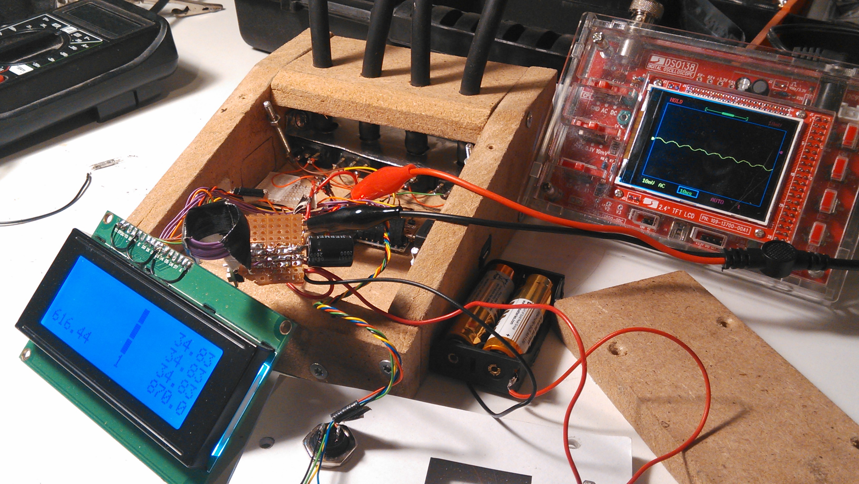
The picture on the main page is the second prototype. It shows the tubes I use for calibration of the sensors. I have to calibrate the sensors because they don't all give exactly the same readings out of the box. The tubes are used to tie them all together and apply the same vacuum pressure. The software then stores calibration values and uses them to calibrate the display. 

The "vacuum pressure" in this case is just me sucking hard... If you have more sophisticated hardware I suggest you use that! The calibration routines have been overhauled and are now much more accurate. 

Features: 

- Balance up to four carbs / throttle bodies (2-4 user selectable).

- digital RPM guage.

- Absolue (bar graphs) or relative (centered around the master carb's values) display.

- Calibration for accurate results, calibration info downloadable to PC.

- Saves settings so you don't need to set it up every time you use it.

- User selectable master carb.

- Display brightness and contrast via software, no old fashoined potmeters required.

- Uses cheap and robust parts.

- Very low parts count, easy build.

- cheaper than most solutions. 

           Ok, lengths of aquarium hose could be cheaper but a PITA to use (IMHO).

- software tweakable to the max, even by non programmers

- User friendly menu system.

- Freeze display feature to make it easier to read numbers and bar graphs.

- Real time data logging to PC via USB (Serial) so you can look at the vacuum pulses for yourself.

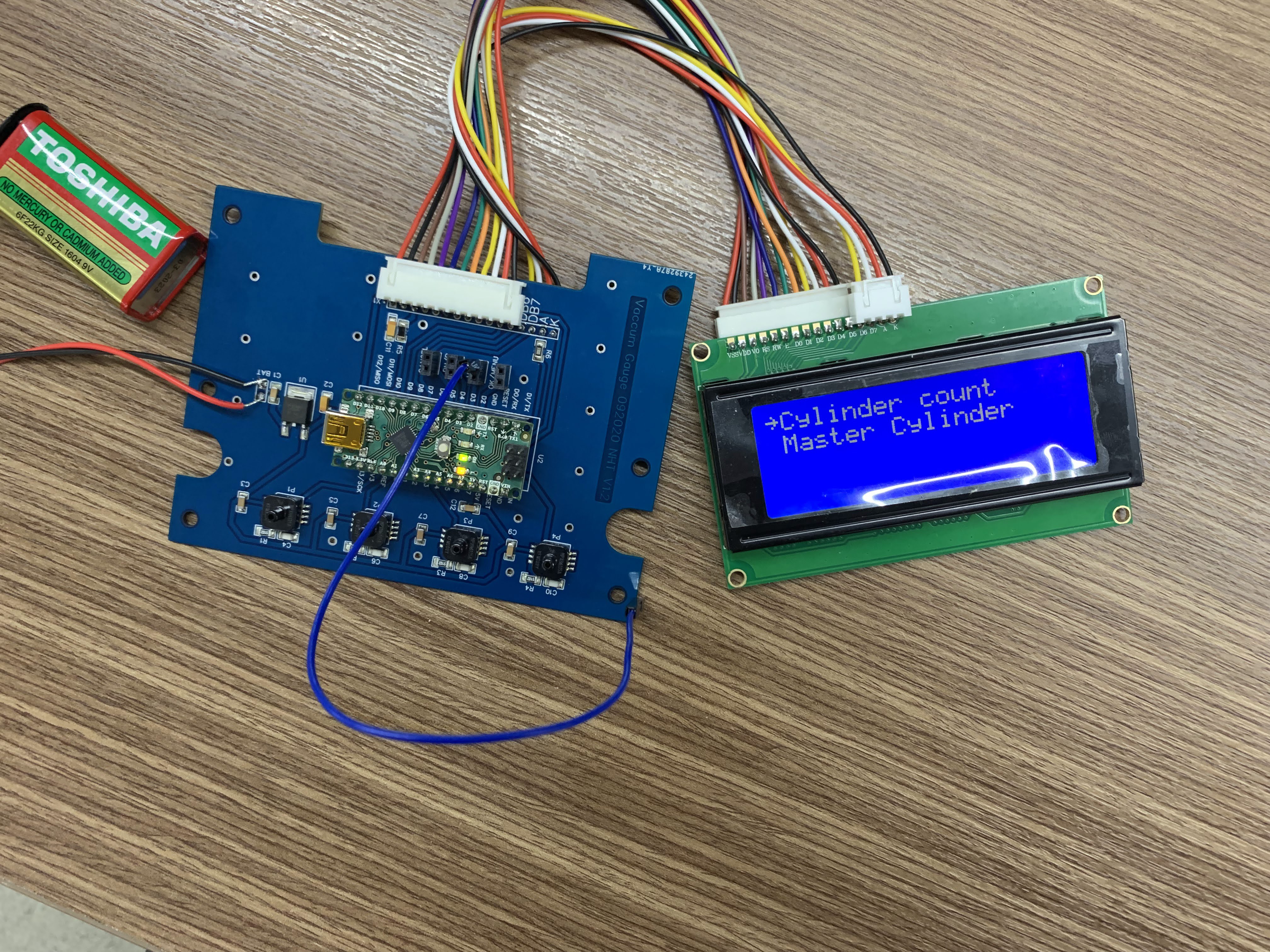
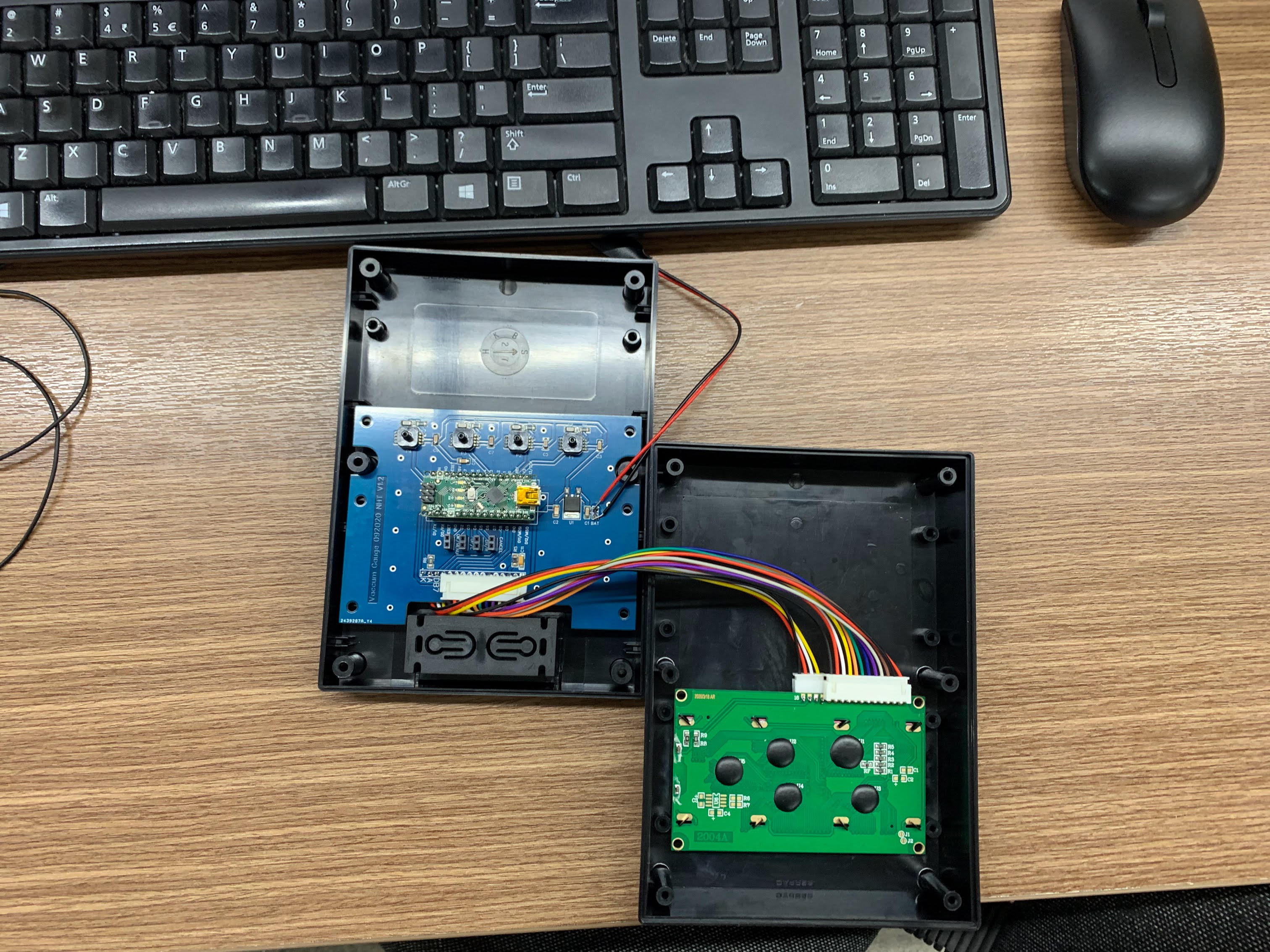
The display is wired up the old fashioned way in the newest CarbOnBal "Basic" prototype. The Arduino has enough pins and I would not know what to do with more pins anyway.

If  you want to build this but need help just drop me a line. I'll do what I can to help you get your own version built. Also if you need help with the software or have tips on improving it, I'm all ears. 

QuickStartGuide.pdf

The Manual for CarbOnBal. Contains everything to get started plus a break down of all available menu items and their effects.

Adobe Portable Document Format - 43.00 kB - 11/03/2020 at 21:01

Preview
Download

Altium_Vacuum Gauge V1.1.schdoc

Altium file for you to eadit

schdoc - 170.21 kB - 09/11/2020 at 06:18

Download

Easyeda_Vacuum Gauge Final in Box For Share V1.2.json

This file is used with https://easyeda.com/editor It's free online software to make PCB

JavaScript Object Notation (JSON) - 179.31 kB - 09/11/2020 at 06:18

Download

Vacuum Gauge_final_11092020.zip

Gerber files for order PCB

x-zip-compressed - 108.34 kB - 09/11/2020 at 06:17

Download

ArduinoPower.sch.svg

How to Power Arduino From One, Two or Three AA batteries.

svg+xml - 270.90 kB - 03/03/2018 at 17:26

Download

View all 8 files

  • 1 × Arduino nano v3 or clone If you get a clone you need to make sure it exposes all the I/O pins, not just a subset.
  • 4 × 09359409-MAP Sensor compatible (or 8093594090) I got these off AliExpressfor about 8 Euros a piece: OEM-09359409-Manifold-Absolute-Barometric-Pressure-Map-Sensor-1Bar
  • 4 × Push button switches I used small PCB switches for the prototype. Any push button make contact switch will do.
  • 4 × MPXHZ6115AC6U (compact alternative to automotive MAP sensors ) Sensors / Pressure, Force. The PCB gerber files is made to use with this sensors. You can get them online for around $14 each
  • 1 × 220 Ohm 1/8 W resistor Used to prevent frying of the display backlight led or arduino pin

View all 10 components

  • Update on Prototype PCB and Box

    TRI NGUYEN11/24/2021 at 08:47 0 comments

    Just update the PCB and Box

  • Update: Put everything in the Box

    TRI NGUYEN09/15/2020 at 03:22 0 comments

    Update: put everything in the box

  • CarbOnBal updates and Laptop software released

    dennis04/20/2020 at 19:17 0 comments

    Hi everyone, I just spent a lot of time tweaking CarbOnBal so this is a heads-up for existing users to get the latest updates from github. There have been a lot of improvements, particularly to usability. This makes it simpler to use out of the box. The previous versions had too much clutter and variables that all had to be set up just right.
    The latest version just works, straight out of the box, with no incidental "hanging meters" artifacts.

    This also marks the first official release of the laptop (or desktop) companion app.

    https://github.com/dennisMe2/CarbOnBal_Laptop/releases

    If you have java installed you just download the .jar file and double click it.

    This gives you access to bar charts, meters and a graph for detailed analysis.

    To use, just connect your unit to the laptop via a USB data cable. The com port will show up in the toolbar. Select the one that CarbOnBal is connected to and hit "connect". Then you can open the windows containing the relevant graphs and meters. A big colorful laptop screen is ideal for fine-tuning. 

  • Can I use X sensor?

    dennis02/16/2020 at 18:07 3 comments

    I just got an interesting question.

    Can I use X sensor?

    The answer depends on three basic properties;

    1  you need a 1 Bar sensor for best accuracy

    2 it must operate at 5V and produce a voltage swinging from as low as possible to as close as possible to 5V for ultimate accuracy.

    3 It needs a 3 pin connector (5V, Ground, signal (in any order, as long as you know which pin goes where)

    We are really looking for a MAP sensor that was designed to work at 1BAR. That means it was originally intended for use in a vehicle without a turbo! This is important because a turbo sensor may go up to three Bar or more and we only need to measure the carburettor or throttle body vacuum (the values below 1 Bar). Going to three reduces the accuracy by a factor of 3 (almost). It would still work and probably still be accurate enough for a decent tune-up, but insane accuracy is one of the main attractions of CarbOnBal!

    It needs to be powered by 5V because that is what our Arduino works with, using a 3.3V sensor would require an extra power supply and a voltage reference, that is more external components and a few lines of programming. It can be done but I can't support stuff I can't test myself.

    There are some crazy sensor designs out there with many pins. I have no idea how to hook them up, and they probably require more external components to use. Stay away from these at all costs. There could be designs that are usable, but you are on your own if you decide to use one of those units.

  • Why can't you calibrate one sensor

    dennis05/24/2019 at 19:44 0 comments

    Someone just asked me why it isn't possible to calibrate all four sensors.

    The reason is simple, its not a bug, its a feature!

    What happens is that the other sensors are calibrated to respond the same as that one (0 in software) 1 in the menu. This means that if that one has a different response curve, after calibrating all four sensors will respond the same way. That actually means its possible that the sensors are responding with less accurate results and that's actually a good thing!

    When calibrating a set of carburetors or throttle bodies, we need them all to respond the same way over the full pressure range the engine can produce, so the sensors need to do the same! We are only interested in differences between the cylinders of the same bike, you are not getting a reading and transferring that to another bike somehow. No we are only interested in relative differences between the sensor readings. All sensors could be off by 50% and it would still work as long as they were all off by the same 50%!
    Luckily these sensors seldom have more than 2% variation and that is easy to calibrate out. Actually doing this is what makes CarbOnBal crazy accurate. 

    Don't believe the hype on those expensive electronic units that claim to not require calibration. They never bother to explain why... And no "Advanced electronics" is not an explanation. The only system that actually doesn't require calibration is a mercury manometer setup even the old aquarium hoses (at least in theory!)... The others are just always off by a bit, but they should be within usable tolerance anyway, certainly well within the manufacturers specs. 

    Compare it to using the old aquarium air lines to tune. You don't care how much liquid is in the tubes as long as all the tubes are the same diameter and one line is not pinched, for example. Nobody takes their aquarium hoses in to get them calibrated, there's no need.

  • Back to batteries

    dennis08/25/2018 at 17:58 0 comments

    I was experiencing intermittent noise from the boost converter I used to run the system off 2 AA batteries. I tried different capacitors but I just couldn't get it 100% ironed out.

    Unfortunately I no longer have a really good high frequency scope to check out what was actually going on. Maybe I should have sprung for a better quality boost board with post regulation or something, but I couldn't be bothered waiting for Ali Express. 

    In the end I decided to just go with a whopping 6 (yes, six) rechargeable AA batteries and feed that into Vin. That way the Arduino's on-board regulator takes care of voltage regulation, and it does a pretty decent job at 7.2V (much more efficient than at 9V). I haven't done the math but these should last me more than long enough.

    The hardest part was extending the housing. But that is still the same ugly-ass MDF board and not hard to do. I just bolted an extension on the back with some left over IKEA screws I salvaged from an old piece of furniture. Looks ugly, weighs a ton bot no more intermittent noise throwing off my calibration and really easy to hook up.  

  • Ride On, Wouter

    dennis06/11/2018 at 09:18 0 comments

    Wouter was my fellow contributor to this project, and a fellow electronics and motorcycling lover.

    Unfortunately Wouter recently died in a traffic accident while touring in Luxembourg.
    I never got to meet him personally but he was a likeable guy, and a very active member of the Dutch motorcycling community and a couple of classic car clubs also. He will be sorely missed by many, many people. Not least of which are his girlfriend, friends and family.
    My condolences go out to all those who feel the loss.

  • Laptop Application in the Pipeline

    dennis06/07/2018 at 18:31 0 comments

    I couldn't resist and after a bit of kicking around I decided to build my own graphical app for the laptop. Its written in Java and should run on Mac, Linux and Windows.

    This allows me to simulate an attached engine for easy and faster debugging. It also has the added advantage of not waking up, or gassing, the neighbors kids.

    What it also does is provide lots of cool new ways to visualize and save the data coming out of CarbOnBal. In the first prototype version I have Bar graphs, a running plot and four gauges, which pretty much covers the ways we all used to balance our carburetors, for nostalgia's sake!

    Right now its clunky and probably broken in more ways I'd care to count but ts a start and I figure it will be a great addition, especially for those looking to balance 6 carbs.

    The software lives in its own location:

    https://github.com/dennisMe2/CarbOnBal_Laptop

    Right now its pre-alpha so you're on your own! I'll let you know when it becomes usable. 

  • Simplifying

    dennis05/19/2018 at 19:14 0 comments

    Just a quick update to let you know what's up!

    I'm getting to the stage when I need to clean up some of the clutter that has made its way into the code. I have three different approaches to calculating averages and I need to settle on what works best. Probably a mix of the different approaches. 

    I also added a diagnostic (text only) display to help me see what's going on under the hood. I might even leave that in, it seems to have merit now that I have come up with a good responsive averaging method.

    Planned is a Bluetooth interface to a mobile phone or tablet which could run an app to support up to 6 carbs, much better graphics and advanced diagnostics etc. This is one for the long term though, and I may let it go if it turns out to be too involved. We'll have to wait and see where it goes.

    Its also great to hear from those who have built their own units! I look forward to hearing more from you and would love to get your feedback on how to make CarbOnBal even better!

  • Betteries, bettered! [Advanced]

    dennis03/03/2018 at 16:16 0 comments

    It turned out that the little el-cheapo boost converters I have laying around are a little too cheap to use out of the box. They wrought havoc with my calibration routine and general accuracy.

    Luckily I was able to borrow a 'scope' from a friend and come up with a practical (simple, cheap) solution. 

    What this converter needed was a filter so I tried just slapping a humongous capacitor on the end. I like to keep things simple. Unfortunately the capacitor on its own wasn't working because it caused the switching regulator to unregulate. It needed a proper coil to make what is known as an LC filter. This can be tailored to lose the high frequency switching noise from the regulator and the mains noise which is picked up over the air.

     So I unsoldered a couple of coils from an old broken down router I had lying around and tested those, they worked well, very well. I also tested a coil I made from gaffer tape and 1.2m (4ft) of wire I had on stock. I just wound the wire on the end of a marker pen and glued it together with the tape. It works, not as good as the 'commercial 150uH coil I unsoldered, but well enough to not impact the calibration routines.

    The capacitor I ended up using was a 470uF 6.3V electrolytic. Small enough to fit well. 

    Here's a picture of the hand wound coil I tested. That's the purple and black round thing above the center of the LCD screen. You can see the 'scope indicating a ripple of about 4mV which is actually really good. This big a coil will aggravate the 50/60Hz mains hum though, but the capacitor will handle that, no sweat.

    To be honest I ended up using a 150uH coil I unsoldered from the old router because it was much more compact and works a tiny bit better. But this will do in a pinch!

    It also helps if you mount the boost converter physically farther away from the sensors and Arduino. I ended up sticking it in the same place anyway, because of space constraints, no biggie.

View all 19 project logs

  • 1
    Study the schematic diagram

    Before jumping into the electronics part you need to get familiar with the circuit so it holds no surprises.

    This isn't too hard. Grab the schematics off github or the files section and take a look.

    I'll wait while you download and view the diagram....

    Ok, got it? Now I'll talk you through it from left to right.

    On the left are four squarish boxes that represent the MAP sensors. I'll assume you are following my exact build. Anyone doing their own mods should know what they are doing, right? The diagram is set up so that the pins in the diagram correspond to their real-life locations. This makes it easy to wire it up and check your work as you go.

    Beginners please note that wires drawn crossing each other in the diagram are only connected if they have a dot on the junction. Rectangles are resistors (its a Euro-style diagram), US style uses squiggly lines but they mean the same.

    Sensors

    The sensors are really simple (electrically speaking). They each need a wire to +5V and Ground to do their thing. Then they will constantly output a voltage (the third wire) that is proportional to the pressure sensed. Less voltage is lower pressure down to 0V at 150Mbar above absolute vacuum, and up to almost 5V at atmospheric (sea level, nice weather, no hurricane touring the neighborhood).

    The signal wires from the sensors are connected directly to the Arduino analog inputs A0 through A3 where the software can measure the voltage they give off. Keep these short in your project and don't go through a connector but solder directly to the board or to a pin header. This reduces interference.

    Arduino

    Now comes the Arduino. It too just needs V+ and Ground to work. Actually, you can feed it anything up to 18V (It will make its own 5V if it has to) so you could directly connect it to the vehicle power. If you want to go this route, feed the higher voltage into the Vin pin. Use the +5V for the sensors. You'd probably fry them with anything even slightly above 5V. The schematic uses a model of the arduino with all the pins in the proper places. This is an Arduino nano v3 type.

    Switches

    The next thing you may notice is the four switches. These are just plain and simple push buttons that make contact when you press them. One side is connected to an Arduino digital pin and another is wired to ground. This keeps things nice and simple to hook up.
    However, if you like to play around with stuff then be very careful you NEVER set the Arduino pins connected to these switches to output HIGH (5V) or the switch will short the pin to ground when pressed! If that happens you may be lucky and find another pin that still works, but don't bet on it.

    The lone resistor

    R4 is a resistor that is in there as protection for the Arduino. The power used to drive the backlight LED of the display is limited by this transistor so the Arduino doesn't fry. Some LCD modules have this resistor, some don't. I figure a slightly dimmer backlight is better than a Kentucky Fried Arduino. In fact my second prototype screen came with a resistor already. I noticed it was rather dim after I fired it up. I just cut out the resistor and it now draws 28 mA, which is perfectly acceptable to me and my Arduino.

    The dynamic Duo: R3 and C1

    These connect to the contrast setting on the LCD display. You often see some sort of adjustable resistor or (POTentiometer) used for this but I thought I'd rather do this in software.

    R3 is there to limit the current flowing into C1. C1 is used to smooth the signal coming from the Arduino. This is a pulsating PWM signal that can make these types of LCD flicker horribly and even become unresponsive. Don't ask me how I know. These two together do a great job at the frequency the Arduino software does PWM.  This is known as an R/C network and you can forget I said that.

    LCD display.

    Last but not least is the display. Its a HD44780 compatible 20 characters by 4 lines display. These are easy for the Arduino to drive and can be tricked into displaying nice bar graphs with up to 100 segments. They can also be read in the dark or even in bright sunlight (if you turn off the integrated backlight!) In fact, there are displays without a backlight altogether, you may prefer using one and can then skip the backlight wiring.

    This display has a 4-bit parallel mode of working which we use that saves 4 pins. The other lines we need to connect are signalling lines that tell it t o turn on and accept commands offered up on the four data lines we are using. The other four data lines are happily hooked up to the +0V. 

    I've got the Power!

    Finally there's the issue of power. As I explained above you could just plug vehicle power into the Vin pin of the Aruino (that's +12-14.8v) which should work just fine. In theory its scary as hell, but it works for a lot of folks. The MAP sensors we have are automotive and can handle some abuse. I have run Arduino's on worse (Joule thief anyone?). 

    What I recommend for beginners is just hook up a 9V alkaline block, which will happily power your circuit for up to 7 hours, more if you are diligent with the on-off switch!

    Power switch

    It goes in the V+ line between the battery and Vin on the arduino. Its a simple single pole single throw rated for peanuts and low voltage.

  • 2
    Think about a layout or box

    If you want to build this project I suggest you think about a box first. My prototype proves the electronics and software works. For the new prototype CarbOnBal Basic, I wanted a box, it looks better and is much easier to handle. 

    My design (if you can call it that) was quickly thrown together on the workmate in the shed. Then I improvised my way out of trouble. I sawed the box by hand out of MDF I had available. To aid in futzing around with the prototype I screwed the six boards and the perspex together without applying any glue. 

    Lessons learned

    What I might do differently is leave more room for all the components. My LCD fits snugly and I had to cut down the tabs on the sensors to get them to fit four in a row. To its credit it s easily handheld this way. Whatever you choose to do I recommend waiting till you have the sensors and LCD in hand so you can fit them in place as you go. I'd also recommend mounting the sensors upside down to prevent stuff getting in there and messing them up. The spec sheets also recommend doing this, but I only really studied them after I built my prototype. 

    Front panel

    The front panel is simple perspex with some carefully drilled holes. Drill in small increments to prevent tearing the ridiculously fragile perspex. I have an SVG drawing as a design inspiration in the files section and on Github. I printed the SVG on plain A4 paper with a laser printer and cut out the holes with an x-acto knife. It was made using Inkscape, which allows you to precisely adjust the layout to match your real-life version. 

    After fitting the paper I screwed in the switches and wired them up.

    Display mounting

    I mounted the display on four threaded rods (3mm) that were simply drilled into (almost through) the bottom of the box and glued there. Then I wound a 3mm nut down each rod to the required height for the display, and it rests on those. I applied some loc-tite to keep them there. Four bent paper clips would do as well! The display is held in place by the perspex panel and does not need to be screwed down.

    Sensor mounting

    The sensors had to be trimmed down so I used the old dremel and a mitre-saw to carefully pare them down so they'd fit snugly. Then I grabbed a scrap strip of aluminium and drilled four holes for the air hose fittings. This strip holds the sensors in place and I just screwed it into the sides of the box.

    Battery

    The battery sits in the space behind the sensors and is easily reachable by removing the back cover. There is an option to power your CarbOnBal unit using cheap AA batteries. Tale a look at the included schematic in the files section. Reserve space in your housing if you decide to use three or four batteries, as they take up much more space than a simple 9V block!

    Arduino. 

    I ordered a micro to mini USB adapter which I fit into the wooden side. The Arduino goes into that and it is held at the other end using a tiny little screw. Of course, you may have a box made of thinner material, and in that case an adapter would not be needed at all.

  • 3
    What You'll Need

     To build the electronics you will need:

    Tools:

    A soldering iron. Any cheap soldering Iron will do just fine.
    A pair of small side-cutters for cutting the wire. 
    A wire stripper, although you can use the side cutters or a knife if you're very careful.
    Some insulation tape or gaffer tape to cover the resistors that go to the display. Or use some shrink stocking if you have it. 

    Materials (in addition to the 'official' parts): 

    Soldering tin, 60/40 flux core works best, or use the new lead free rubbish if you have to.
    Tinned copper wire on a roll, or re-use some wire from an old ribbon or network cable you have lying around. In that case, take care to pre-tin all stripped wire ends before making the definitive solder joints or you risk overheating the Arduino. 

    If you want to make use of the option to use AA batteries, then you'll also need a clip for them and a DC-DC Boost converter.

    Mounting hardware:

    You will need to put the electronics into a box and may need an assortment of screws, tie-wraps plus whatnots and thingamybobs. This all depends on your particular solution.

View all 10 instructions

Enjoy this project?

Share

Discussions

Viktorijoski wrote 12/11/2023 at 13:53 point

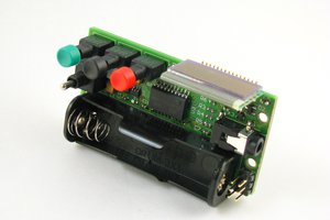
I like this project and have already ordered most of the crucial parts to build this carbs synchronizer tool but I have one question. Is there any chance you have PCB layout for the MAP 09359409 sensor because I really like to make it as I should and not with wires hanging around. Thanks a ton for this project!

  Are you sure? yes | no

yanickr wrote 01/26/2023 at 01:11 point

Hi, First a big thank you for sharing this project. I am in the process of building my Carbobal. Everything works great (Still waiting for my Map sensors so I replaced them with potentiometer just to play around) Here is my question: I will only be using two sensors, should I tie the two unused inputs to gnd to prevent inerference or this changes nothing? Thank you for your time!

  Are you sure? yes | no

dennis wrote 09/21/2023 at 08:52 point

Have been busy with other things. It doesn't really matter if you tie them to ground or not but it certainly couldn't hurt.

  Are you sure? yes | no

gavin wrote 08/05/2022 at 02:52 point

Hi, I love this project and all the features in the software. If you see this I'm wondering if I could use your pcb with one of the new HD44780 that come with i2c adapter. It looks like pins A4 and A5 on the Arduino nano aren't used which are SDA and SCL. I guess it would be a waste of all those data pin pads?

  Are you sure? yes | no

dennis wrote 08/08/2022 at 20:42 point

Well, the number of pins doesn't matter to me. What I consider a waste is the amount of RAM consumed and the timing limits imposed by the external libraries / protocols they use.

Another major consideration was that I wanted to keep the basic project simple. There are a number of slightly incompatible I2C implementations out there, and I would have had to spend countless hours helping less experienced builders debug their projects and tweak the I2C settings. Wiring up three? more wires actually simplifies the project and is easy to debug, because you can see what's going on, as opposed to finding out which bits to flip in someone else's undocumented Chinese knock- off display interface.

However, if you really want to try it, and you have the electronics know-how, you might as well go for it! It might even fit in RAM of you are lucky. To test this, try calibrating the sensors. If the unit doesn't crash it is probably OK. Testing the 1ms per four sample timing can be done using the Java front-end.

I'm very busy right now, and will be for at least three more months, so I really can't provide much support, but it would be interesting if you could pull it off!

  Are you sure? yes | no

gavin wrote 08/10/2022 at 04:20 point

Thanks for getting back to me, I just saw your comments on github on i2c, I was not aware there are potentially different implementations. I guess I will find out if it works when the parts get here! If it does I will post about it.

  Are you sure? yes | no

gavin wrote 09/25/2022 at 20:00 point

Hi Dennis,

I got the carbonbal basic working with i2c with just a few changes. I am using a cheap LCD off aliexpress with the PCF8574 chip acting as an adapter from i2c to serial. The extensible HD44780 library by Bill Perry works as a drop in replacement for the Liquidcrystal library with only one or two changes. Memory use appears to be ok since I could run calibrate functions.

Just one issue I am having is when I change the graph type I get a "settings write error," but the graph type is correctly changed so it does not look like a big deal.

I didn't end up using the pcb anyway since I got the 09359409 MAP sensor, not the surface mount ones.  The code for it is here https://github.com/atkinew0/CarbOnBal .

I plan to make a video tuning my carbs when I get a proper enclosure put together (famous last words).

  Are you sure? yes | no

AksTheNerd wrote 02/19/2022 at 16:29 point

Hello Dennis. I just found this tutorial and i find it interesting so i decided to start looking up the parts i can get locally. I was looking at a MAP sensor i found that is cheap from the naturally aspirated gasoline engine, working with the same voltage but the range is 20-100 kpa. I have seen the SMD sensor used by some is 15-115 kpa. My question is, will the 20-100 kpa be good enough for this, or do i need to modify the software or is it unusable? 

  Are you sure? yes | no

dennis wrote 03/26/2022 at 19:41 point

It should at least be usable, but we regularly go over 100kPa locally. Tuning is all at a partial vacuum anyway, so you should be fine. Even if there was clipping due to low vacuum on a hot day at sea level it would be the same for all cylinders, so shouldn't be a problem.

  Are you sure? yes | no

brettkendall89 wrote 10/17/2021 at 03:05 point

Hello, I've just built this unit. Thank you for all the work you did designing it. I am having an issue with calibrating the sensors. Without calibrating them sensor 1 reads about 864 with no vacuum applied to it. Sensors 2-3 all read the same about 854 +-1. When applying vacuum all 4 sensors respond about the same. After I calibrate sensors 2 and 3 read much lower for some reason maybe about 760. Also sensors 2 and 3 will wander a lot more. When first applying vacuum they will seem to read correctly, but as you hold the vacuum they will start to wander. In that time the vacuum applied to them is not changing. I am using a hand vacuum pump for setting them up. I  think that there might be some software issue, but I don't know. It seems like the sensors work fine before calibrating and not after. Please let me know if you have any suggestions.

  Are you sure? yes | no

dennis wrote 10/25/2021 at 11:49 point

That is very strange indeed. I have one of those pumps so I should be able to replicate it. If you suspect there is a problem with your calibrations, you can clear the calibration data from the menu. I may not get around to fixing this soon, but I will check it out when I have time.

  Are you sure? yes | no

andreas milke wrote 03/21/2021 at 17:12 point

HI Dennis, I'm from Brazil and I developed my own Carb Sync for two carbs using Arduino, I saw your project and it is amazing.  

I saw that your project can measure rpm, but I didn't see any sensors attached to the electronic circuit. How is it possible to obtain the rpm?

is the latest version of the program the beta2 version?

  Are you sure? yes | no

dennis wrote 04/05/2021 at 08:35 point

The beta 2 is worth installing. How the rpm works is it measures the timing between the starts of the dips in pressure on the master cylinder. Together with the number of cylinders I can calculate the RPM. The algorithm isn't perfect though I'm still improving it.

  Are you sure? yes | no

andreas milke wrote 04/05/2021 at 14:32 point

Thanks. I made my own CArbonbal, I would like to test in my Honda C%00K 1973...

  Are you sure? yes | no

tom.langendries wrote 03/05/2021 at 22:56 point

Hey Dennis,

Ik vind jou project echt top. net wat ik nodig had.

Ik heb alles reeds gemonteerd e.d. nu blijkt dat bij het uploaden van het bestand ik de melding krijg met het volgende: TCCR1A was not declared in this scope. enig idee hoe ik dit verhelp?

alvast bedankt!

  Are you sure? yes | no

dennis wrote 03/09/2021 at 18:05 point

Verkeerde board geselcteerd denk ik. Check dat even. Ik heb het ook wel eens vaker gezien bij Arduino projecten. Het zou anders een ontbrekende library zijn, maar dat zou vreemd zijn, dan zou iedereen er last van hebben, en jij bent de eerste die ik er over hoor.

  Are you sure? yes | no

tom.langendries wrote 04/05/2021 at 08:01 point

Hey Dennis, Met de Nano en Nano every kreeg ik het niet aan de praat. ik heb dan uiteindelijk de uno R3 genomen die ik liggen had en het werkt uitstekend. vermoedelijk is er iets mis met da andere arduino's.

Ik ben nu bezig met het maken van een behuizing met behulp van mijn fantastische 3d printer. zodra ik de behuizing optimaal heb (kinderfoutjes eruit) stuur ik jou de bestanden door? dan kan je deze hieraan toevoegen en kunnen de andere de behuizing laten printen. indien je dit leuk vind pm dan even jou gegevens zodat ik ze kan bezorgen.

grts Tom

  Are you sure? yes | no

eraydagci wrote 02/06/2021 at 15:11 point

I see the coil next to the screen in the photos.  for this RPM?

  Are you sure? yes | no

dennis wrote 02/06/2021 at 15:44 point

No, that was an experiment. I was trying to smooth out switching noise. I removed the noise by going back to using batteries!

  Are you sure? yes | no

eraydagci wrote 02/06/2021 at 15:50 point

Thank you for everything

  Are you sure? yes | no

eraydagci wrote 02/06/2021 at 10:32 point

Hello, I'm excitedly waiting for your reply.

  Are you sure? yes | no

dennis wrote 02/06/2021 at 12:52 point

You  need to edit the globals.h file and change P5VSENSOR to 1278 in stead of 1020 for this sensor. That should get you more reasonable values at the cost of some accuracy, but not a problem in practice.
To get it to be as accurate as possible you would need to supply a stable 4V reference voltage to the aRef pin and alter the software to use the reference voltage and not VCC (5V).
This falls outside the level of support I can provide at present.

  Are you sure? yes | no

dennis wrote 02/06/2021 at 12:57 point

I don't know why but I can't reply to your other comments, Hackaday is a bit flakey sometimes!
The sensor you bought is supposed to be the correct type, but 4V max is not correct, it should output almost 5V at sea level. You could complain to the seller, but its probably easiest to adjust the software and work with it. The accuracy will be reduced a bit, but not enough to be a problem in practice.

  Are you sure? yes | no

eraydagci wrote 02/06/2021 at 13:02 point

thank you , ı am trying

  Are you sure? yes | no

eraydagci wrote 02/05/2021 at 21:37 point

Hello Dennis, I built the circuit. energized, all sensors in absolute image are sens.1 = 873
sens.2 = 871
sens.3 = 870
it shows sens.4 = 871 values. map sansor gnd and out measurement value is 4v, when I vacuum this value is between 2 - 4 v and the value on the screen decreases and increases
.
I'm sorry for my bad english .

  Are you sure? yes | no

dennis wrote 02/05/2021 at 21:51 point

Do you live high in the mountains? If so, its OK. Otherwise you may have bought sensors that measure turbo pressure in addition to vacuum. Its possible to edit the settings inside the code to match. It won't really be a problem when balancing carbs or throttle bodies though as only the relative differences really matter for balancing. Let me know if you need help adjusting the software internal settings.

  Are you sure? yes | no

eraydagci wrote 02/05/2021 at 21:57 point

thank you, i live at sea level and bought the following sensor

https://tr.aliexpress.com/item/1005001584534336.html?spm=a2g0s.9042311.0.0.23154c4dOtX3Iv

does the software need a big change?

  Are you sure? yes | no

eraydagci wrote 02/05/2021 at 22:03 point

if you are eligible, i can give you remote desktop link anydesk team viewer

  Are you sure? yes | no

eraydagci wrote 02/05/2021 at 23:10 point

do you have time to help pls.

  Are you sure? yes | no

Walt wrote 11/06/2020 at 07:07 point

I did not get an email

  Are you sure? yes | no

dennis wrote 11/06/2020 at 08:19 point

ok, something appears to be seriously messed up with e-mail. I am getting yours.
See your hackaday P.M.s

  Are you sure? yes | no

Walt wrote 11/06/2020 at 06:55 point

I ran this sketch

void setup() {

}

void loop() {

I ran this sketch then 1.5.4. The old settings are still there.

  Are you sure? yes | no

dennis wrote 11/06/2020 at 07:01 point

Walt, see my e-mail reply.

  Are you sure? yes | no

Walt wrote 11/06/2020 at 06:16 point

Dennis

void setup() {

}

void loop() {

I ran this program then 1.5.4. The old settings are still there.

  Are you sure? yes | no

Walt wrote 11/06/2020 at 04:37 point

I need HELP!

I load 1.5.4 and have remnants from "apparently" the last version. I loaded "blink" and it caused 1.5.4 to not work. I reload  1.5.4 and it works BUT still has all my old settings. It is version 1.5.4. What can I do to erase EVERYTHING?

  Are you sure? yes | no

dennis wrote 11/06/2020 at 05:44 point

Walt, I need to try to replicate your problem on my unit before I can answer that. A 'factory' reset from the menu should have obliterated your old settings. Flashing the new version should have overwritten the old menus. I've never seen them survive a reflash. This will take me a while to test out thoroughly. Hold on. I will get back to you.

  Are you sure? yes | no

Walt wrote 11/02/2020 at 23:44 point

Are the instructions ready yet?

The instructions refer to dampening 0 - 100%. The dampening menu is a EMA factor that goes from 0 - 15. I am not sure what that relates to. The "responsiveness" that is mentioned in the instructions I can't find. Can you help out?

  Are you sure? yes | no

dennis wrote 11/03/2020 at 21:06 point

Walt, I updated the Quick Start Guide. You can now download the pdf from the files section on this site. It no longer contains outdated references like responsiveness. The menu breakdown is in there too with a concise explanation of all the menu entries and their options etc.

  Are you sure? yes | no

Walt wrote 11/04/2020 at 02:18 point

Thanks for updating this, something still does not make sense;

The instructions say; "

In the menu go to Settings / Software Here you will find the settings Damping
and RPM Damping.

When I follow that path I get Settings / Software  then I see (Averaging Method) & (Damping).

.....and inside Damping it reads "EMA factor" and I have only 1 to 15 adjustable.

Do I have something left over from a previous software?

  Are you sure? yes | no

dennis wrote 11/04/2020 at 07:20 point

I can't reply to your last comment somehow!
Yes, it seems your version still has some relics left over from earlier algorithms. It would probably be best to update your software to match the manual.

  Are you sure? yes | no

Walt wrote 11/04/2020 at 17:55 point

I loaded 1.5.4 over the top of the previous version. How do I clear everything and start over?

  Are you sure? yes | no

Walt wrote 10/23/2020 at 17:23 point

Have you written instructions on what the individual menu settings do and how they affect the display and operation? When I loan it to friends it would be good to have "instructions".

  Are you sure? yes | no

dennis wrote 10/23/2020 at 20:10 point

Yes, in the source under documents there is a quick start guide and a menu guide. However, these need updating. Maybe that's a job I can get around to on sunday.

  Are you sure? yes | no

dennis wrote 11/03/2020 at 21:07 point

(Now updated and uploaded to the files section)

  Are you sure? yes | no

Walt wrote 10/23/2020 at 16:23 point

Hi Dennis, I did balance the engine back in April and the balancer worked great. My fellow pilots were very impressed with it and how easy it was to use. I used it again yesterday since there was some slop in the throttle cables and I wanted to be sure of my balance. I am still using 1.5.3, what has changed in 1.5.4? 

  Are you sure? yes | no

dennis wrote 10/23/2020 at 17:10 point

Great to hear you are happy with it. 1.5.4 contains changes to improve the Companion software for use on a laptop. Using a stand alone unit there's no noticeable difference.

  Are you sure? yes | no

Stu wrote 08/23/2020 at 09:41 point

I have ordered the parts for the build. I still have the vacuum gauges I used back in the '70s for the 750/4. It's time to go digital and also remove the guess work watching the ever changing dials. My bike now is a '95 R1100.

  Are you sure? yes | no

dennis wrote 09/08/2020 at 10:11 point

Have fun with the build Stu.

  Are you sure? yes | no

Matthew wrote 03/16/2020 at 11:14 point

Hello Dennis. I would firstly like to thank you for your great project. Nontheless i have some issue, i built CarbOnBal but when i applying vacuum to each sensor values on absolute display don't change.
All of these stuck on "956".  I have four  09359409 sensor from aliexpress. Where is the problem, failed all sensors?

  Are you sure? yes | no

dennis wrote 04/21/2020 at 20:43 point

this means that the sensors are sending close to 5v to the analog ports but not quite..... are you sure they are connected right? you really need to be painfully sure all the connections are correct. check the polarity, are you 100% sure they were connected the right way around? if not, you might be looking at 4 blown sensors. print the schematic and check every line one by one, check them off on the schematic as you go. chances are you may be missing a ground connection or something.

  Are you sure? yes | no

Bharbour wrote 03/06/2020 at 20:56 point

Nice! The days of mercury manometers are gone...

  Are you sure? yes | no

Similar Projects

Does this project spark your interest?

Become a member to follow this project and never miss any updates