 Max.K
Max.KHardware
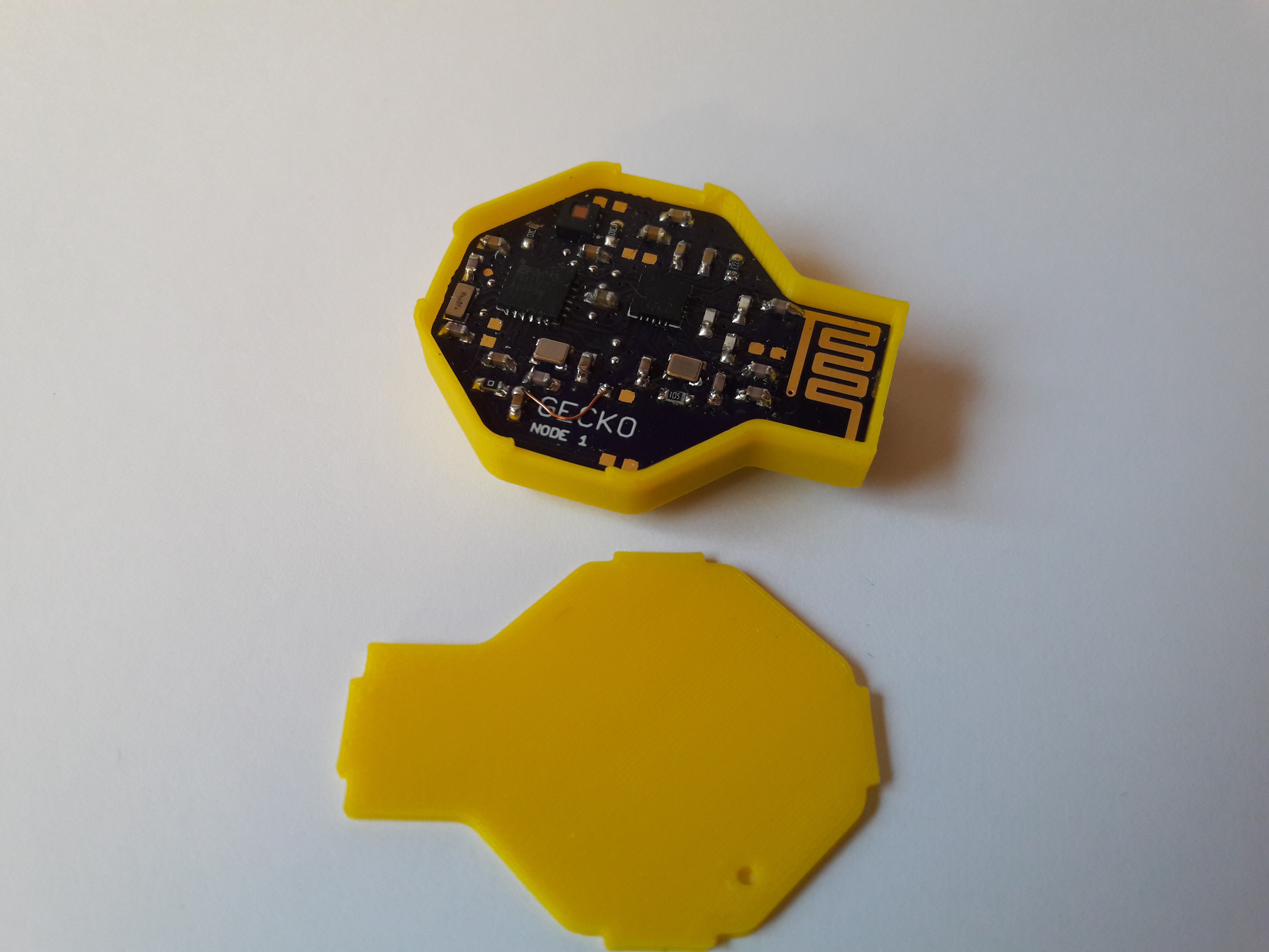
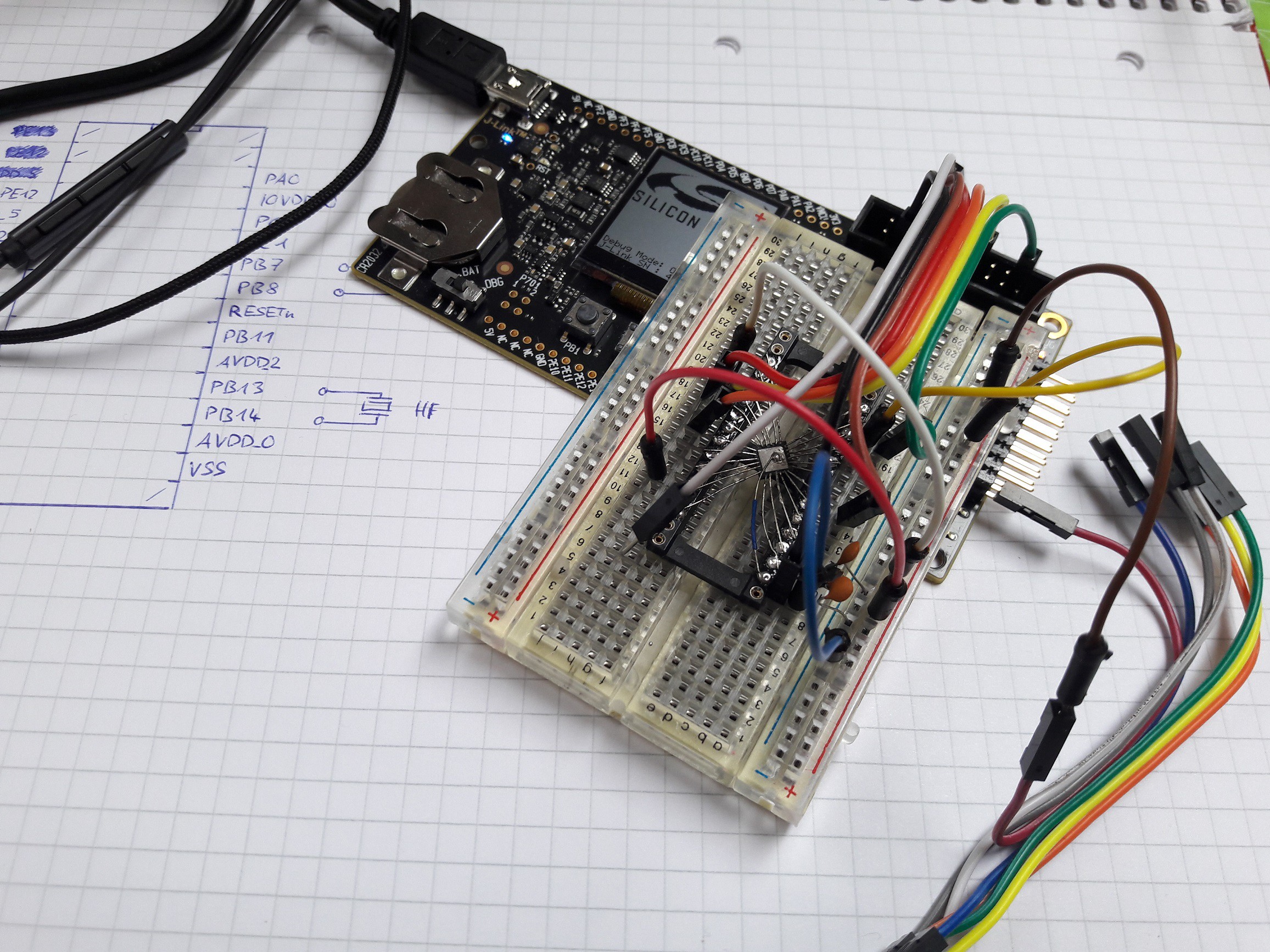
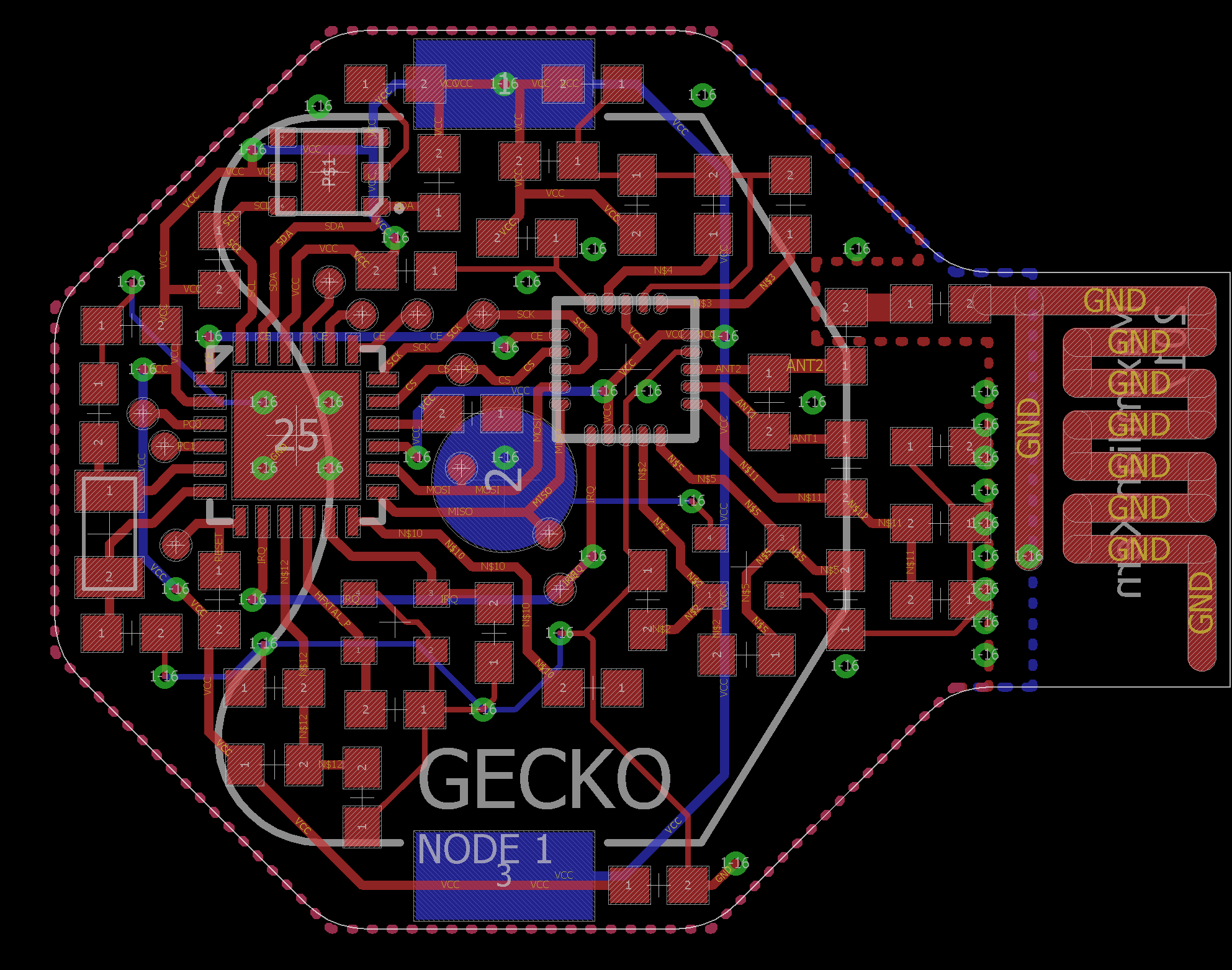
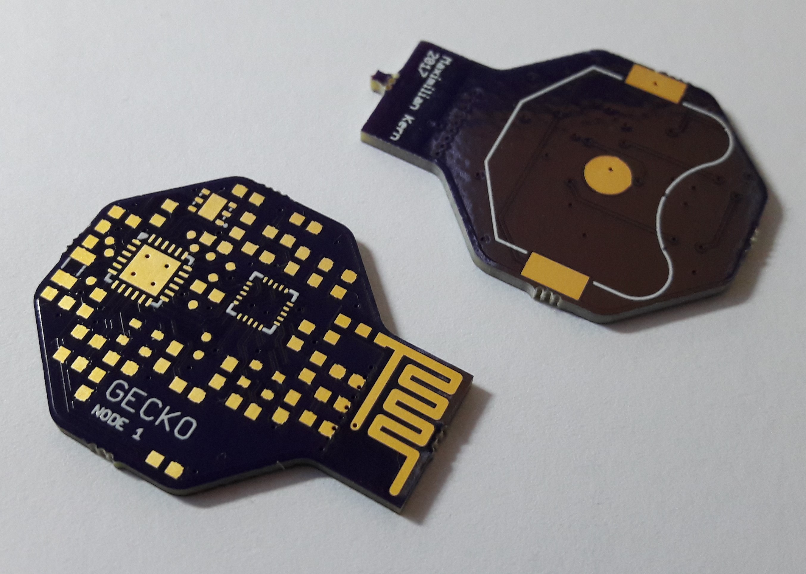
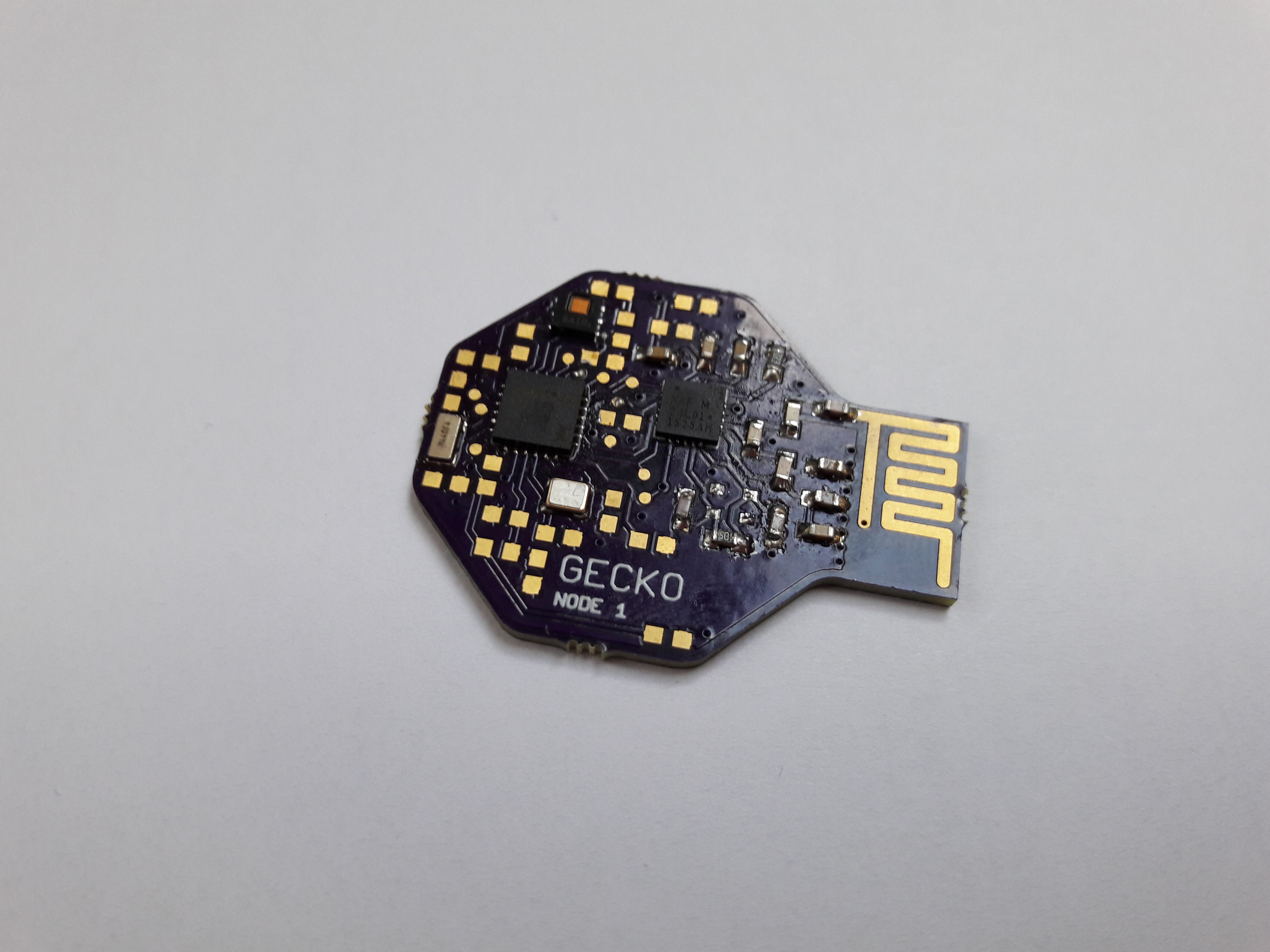
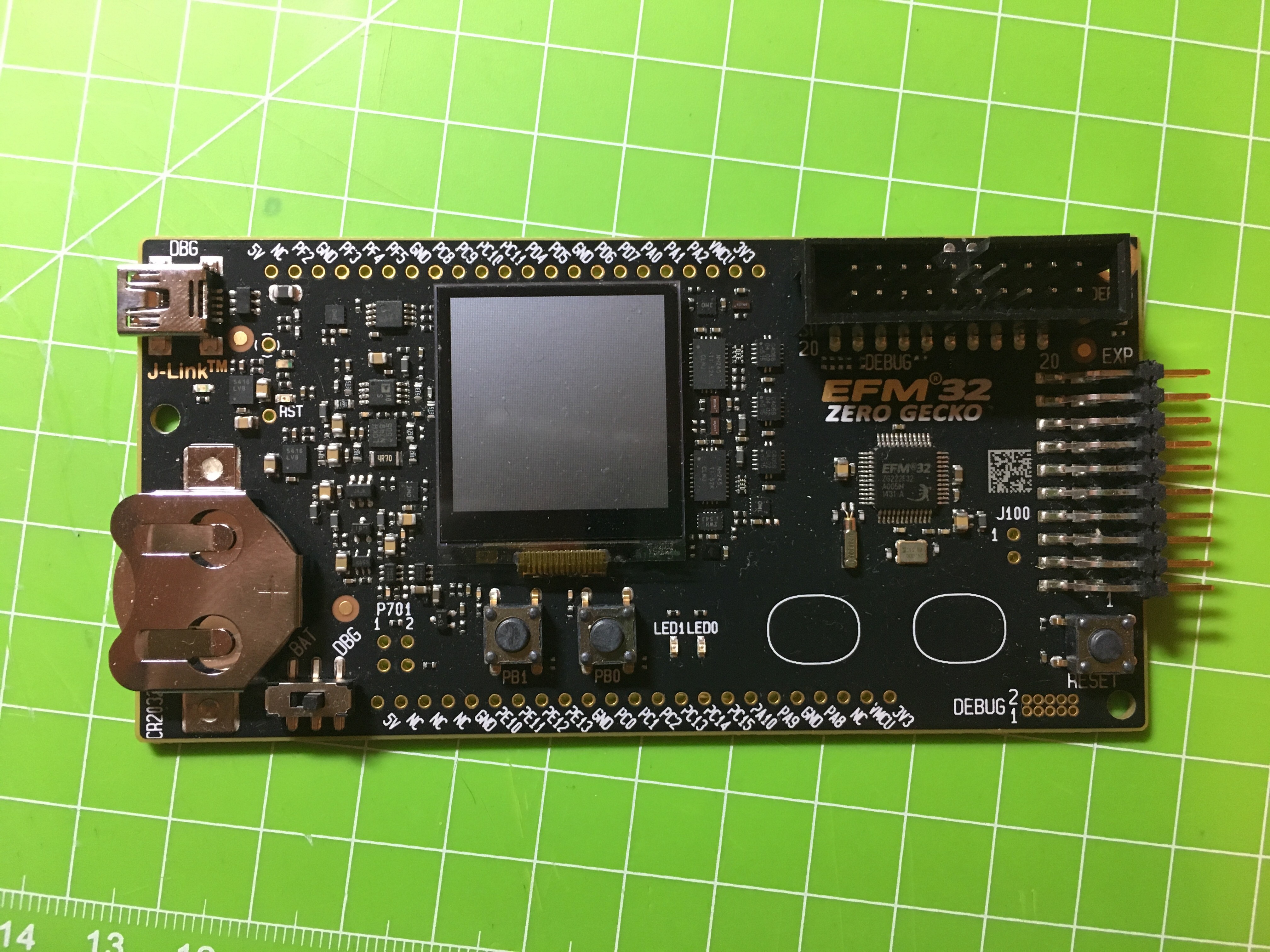
- SiLabs EFM32ZG110F32 Zero Gecko Microcontroller
- Texas Instuments HDC1080 i2c temperature and humidity sensor
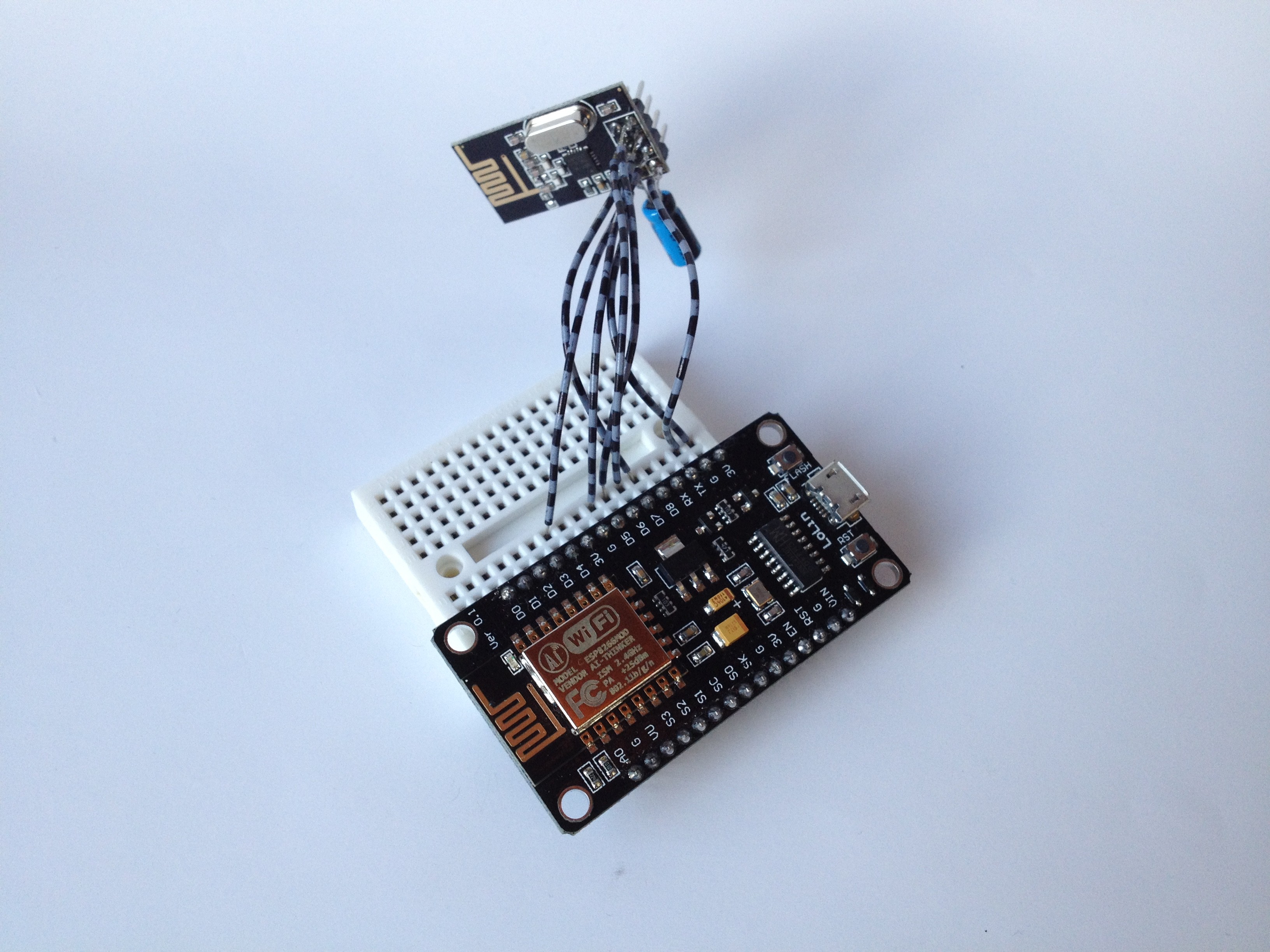
- Nordic NRF24L01 radio module
- Battery: CR2023 (240mAh) coin cell
Features
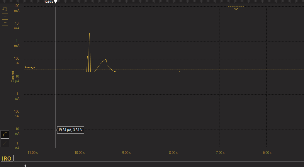
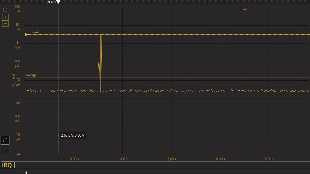
- 8 years of battery life
- Low cost: <10€ per sensor board
- Accurate temperature (±0.2°C) and humidity (±2%) measurement
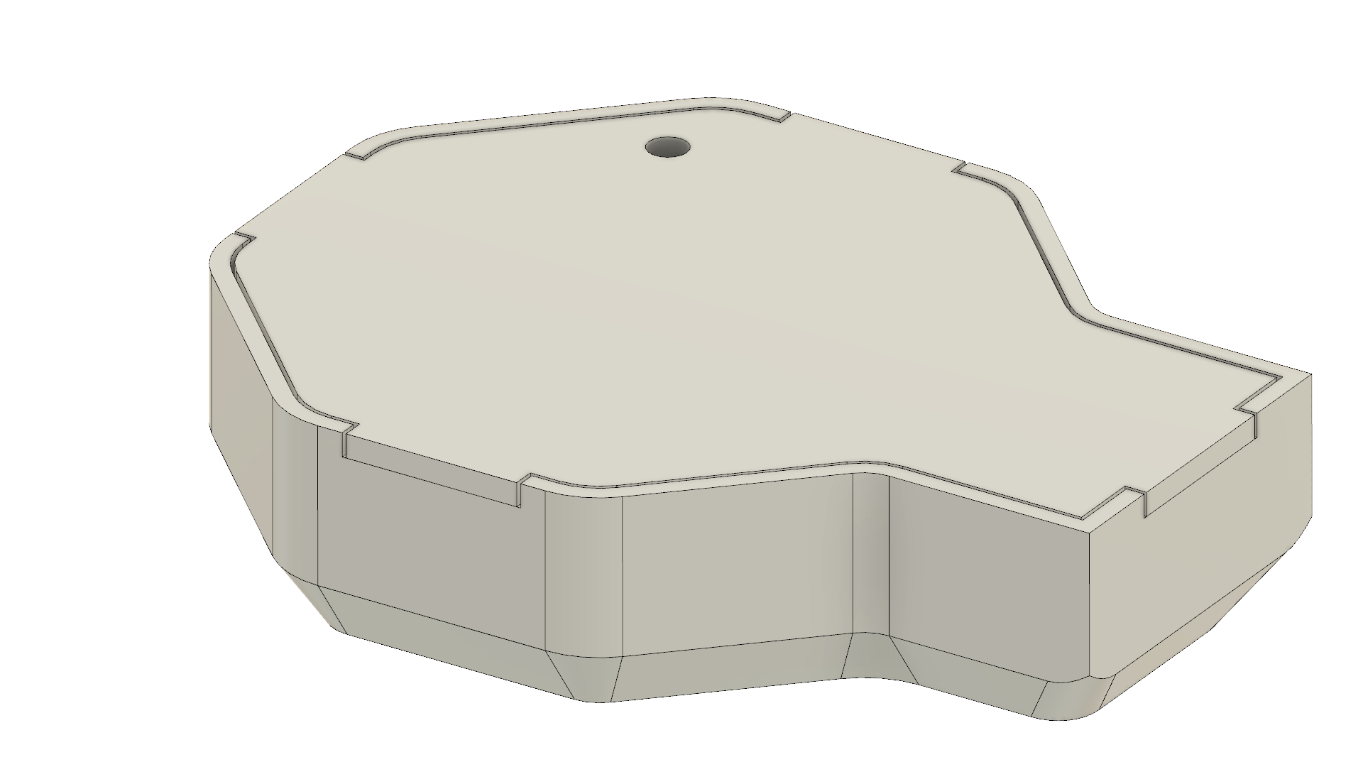
- Compact size: 8.5x36x28mm including the case
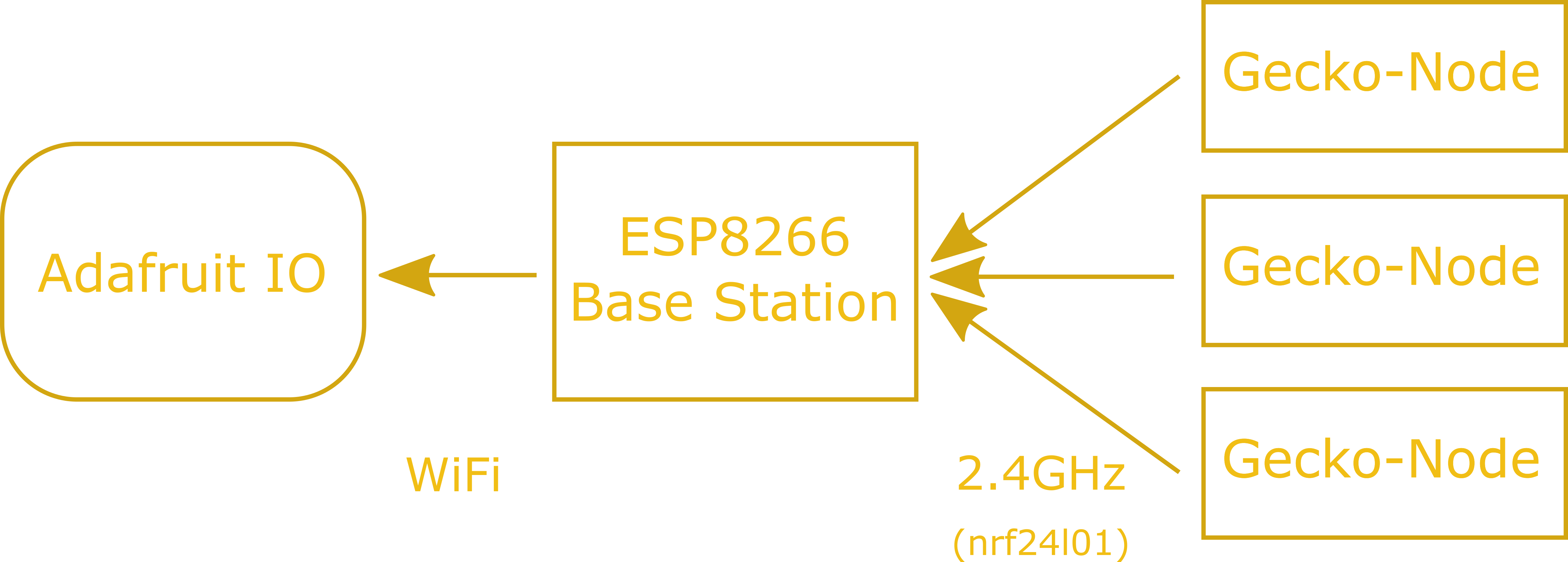
- ESP8266 base station sends data to Adafruit.io
- Multiple Gecko Nodes can be connected to the base station at once


 Andy
Andy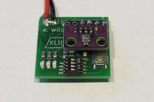
 alnwlsn
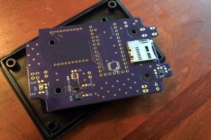
Nice project, I am working on something similar. I will definitive follow your project. :)