 deantonious
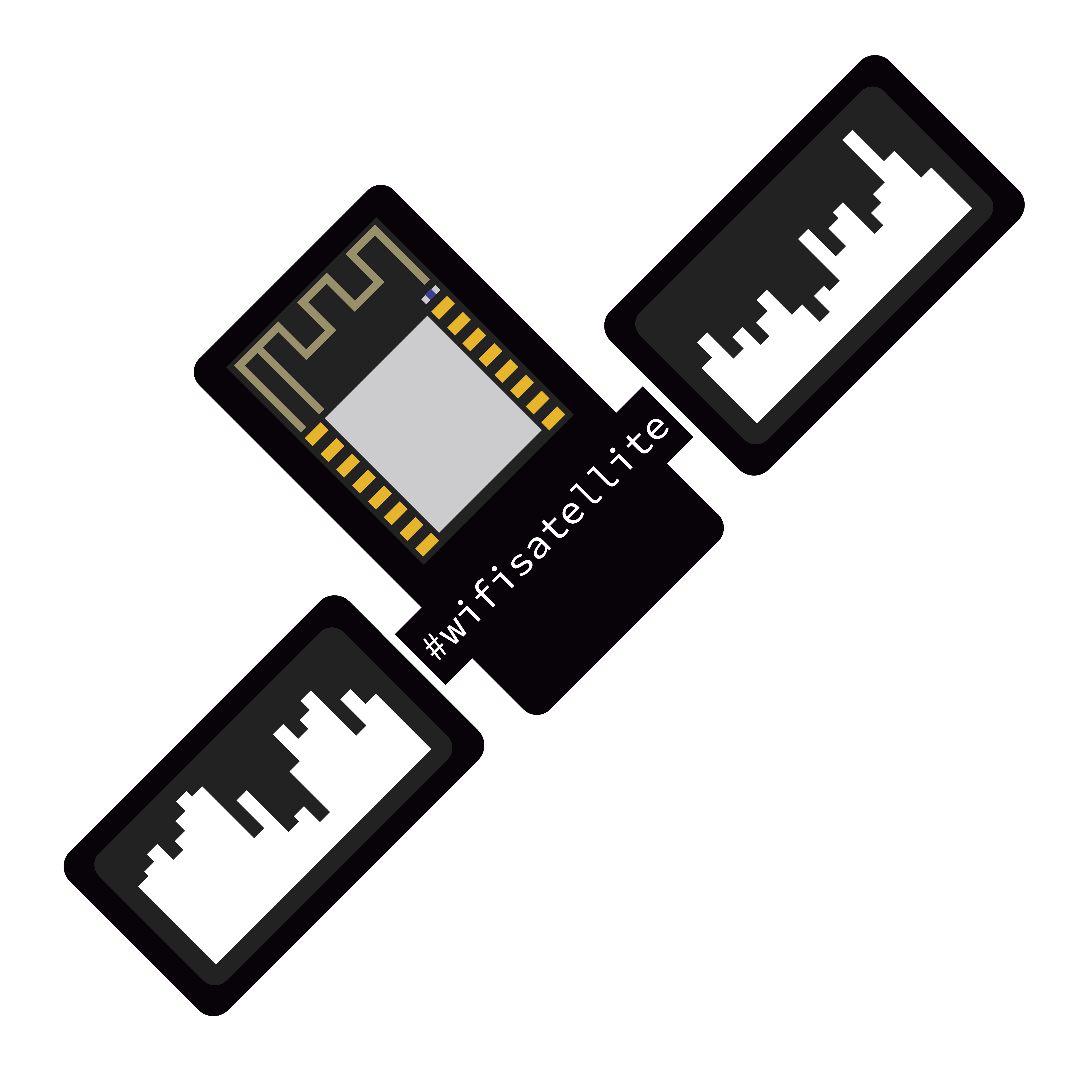
Planning and building!
We were all talking over Discord a few months ago and decided we should do something for the c3. Something cool to show and get in touch with people!
We thought maybe we could do something like the Wi-Fi Cactus from DEFCON:
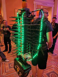
It's made out of Hak5's WiFi Pineapples to sniff as much WiFi traffic as possible!
I said that we could do the same thing just with ESP's! We are all students, so it had be cheap, DIY and open source.
I already made the ESP8266 PacketMonitor before. It shows the Wi-Fi traffic from one channel on a little OLED display.
Perfect for our idea, only one problem... the ESP8266 is only able to sniff the packet header :(
To capture full packets, we needed the more powerful successor: Espressif’s ESP32!
Good that I was already in contact with Travis Lin to make a new PacketMonitor board using the ESP32!
We had a few problems making both the hardware and the software and it took a while…
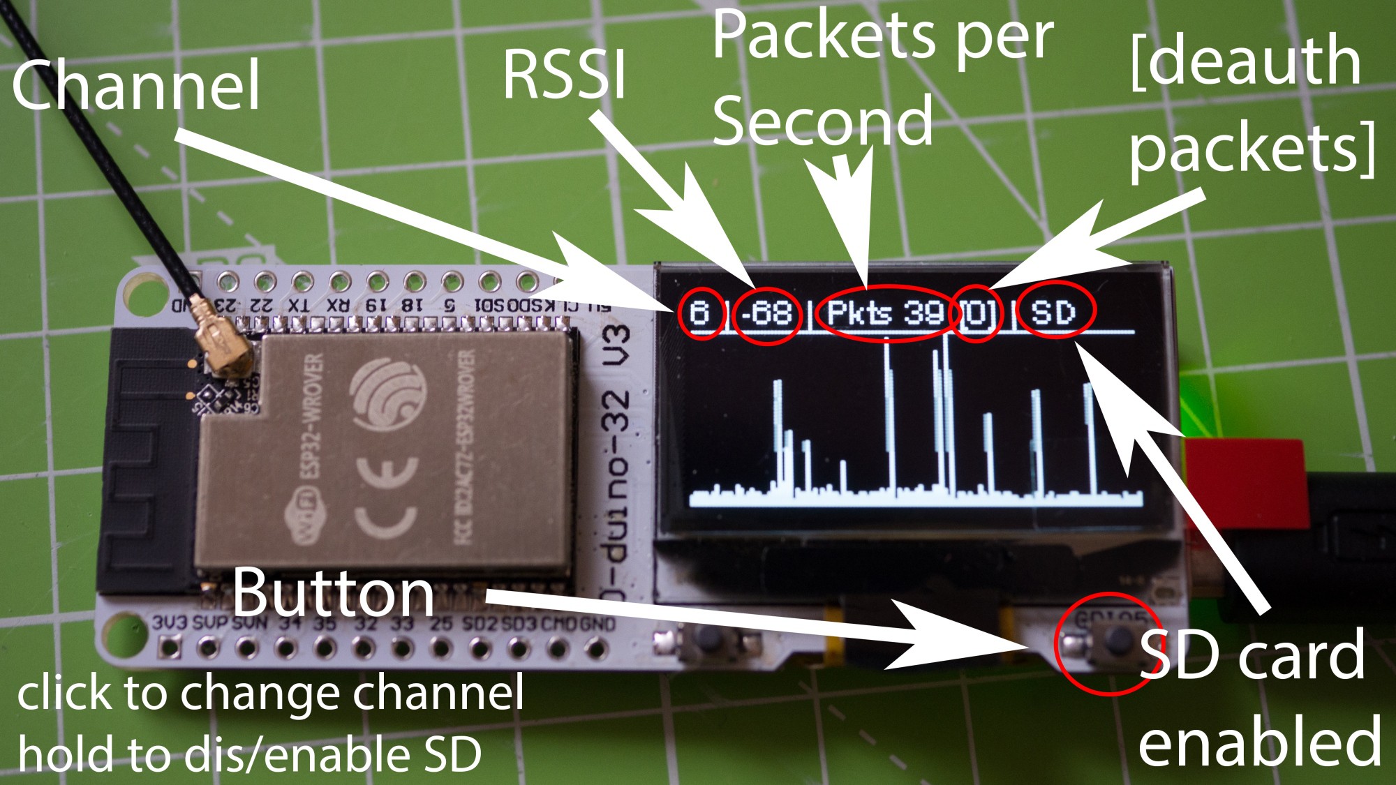
But now we have this great and inexpensive development board with a 1.3" OLED, SD card slot, LiPo charger and the new ESP32 WROVER module with extra RAM:
https://www.tindie.com/products/lspoplove/wifi-packet-monitor-v3-preflashed-d-duino-32-sd/
It comes with the PacketMonitor32 software I’ve made:
https://github.com/spacehuhn/PacketMonitor32/
I told Travis about our plans and he was kind enough to sponsor us 14 of his new boards!
(one for every 2.4GHz WiFi channel)
Because the board already had everything we needed, we only had to think of how to power it, where to get 14 micro SD cards and how we would mount all these boards.
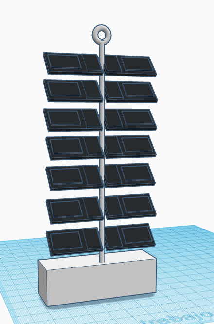
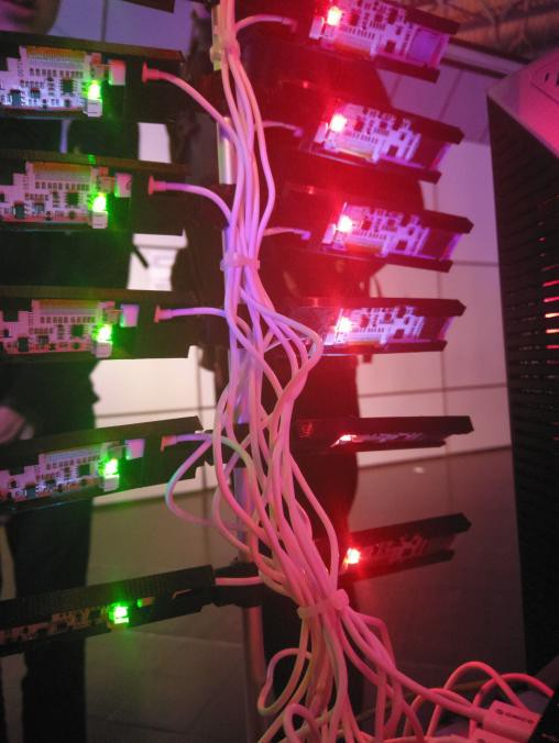
Deantonious, our master of design, had the idea to put them on a stick, so it would look like the solar shield of a satellite (that's why the name *WiFi Satellite*). He designed the 3D parts and printed them.
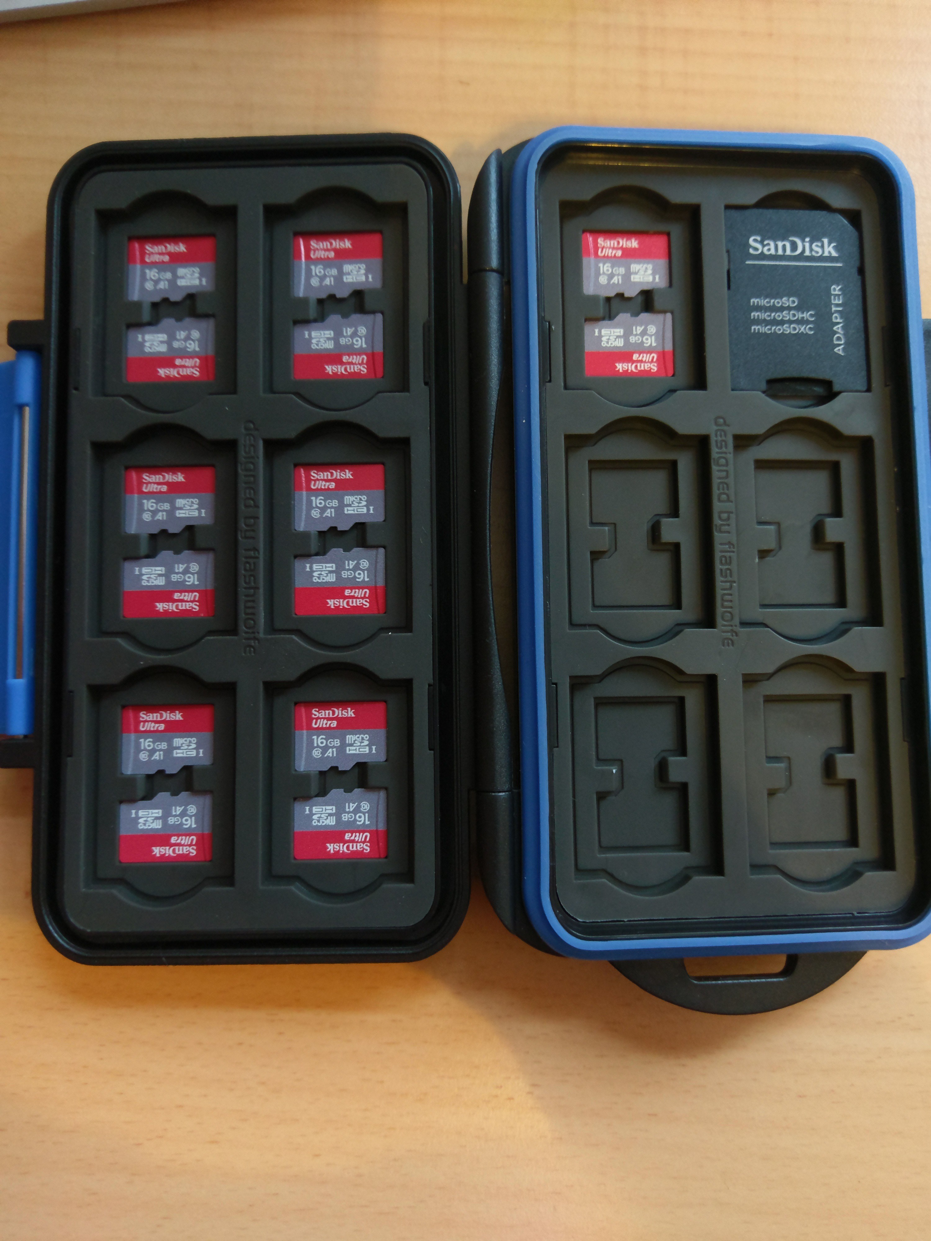
We had many ideas on how to save the whole traffic, but the easiest was to use a micro SD card for every module. That way we wouldn't need a master device and save us a lot of time programming and debugging.
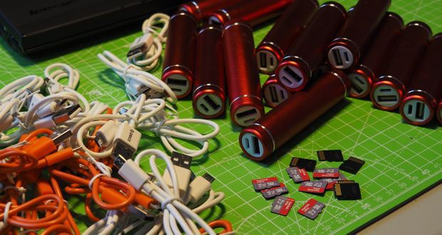
I tested different SD cards and ended up buying 16 GB SanDisk cards from AliExpress (around 6,90€ each). We could have got cheaper cards, but we needed something with enough storage and a good speed.
We also bought USB cables for each board (good thing they cost only a few cents from China) and I was lucky enough to find 2 very good 7 port USB hubs for just 10€.
We wanted to use 18650 LiPo cells to make the whole thing portable and I had a lot of cells from old laptop battery packs.
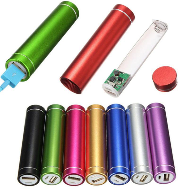
I found these 18650 power bank adapters on AliExpress and bought one for every board.
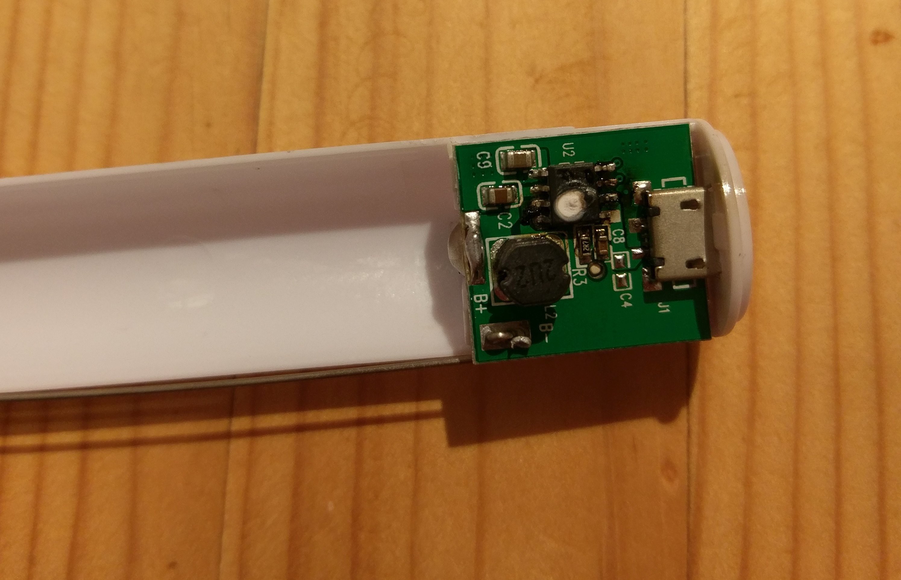
Everything seemed to work fine until I made a stresstest...
they lasted for a few hours (around what I expected) but when I wanted to charge them, two of the power banks started smelling like burned electronics.
It turned out that the batteries were fine, but the charger chip was burned for some reason.
Seemed like these power bank adapters weren't that great after all. Maybe fake charger chips, maybe just two faulty units, maybe they just weren't protected like they claimed on the website.
Anyway, I decided to stop using them. LiPo batteries are not things you want to be around, if they start burning (or worse).
So at the end we kept our WiFi Satellite safe and stationary and it worked just fine! :)
 Alex Hiam
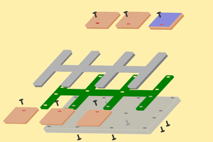
 Krinkleneck
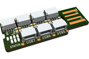
 rbtsco
 Brian Lough
If i flash the packet monitor 32 code into a normal esp32 and change the boot button definition to GPIO0 and attach an SD Card Module to it, Will it work?