 lion mclionhead
In the dinosaur age, we only had analog microphones with big XLR outputs, 48V phantom power, & preamps. None of this USB nonsense. The big connectors were cool, anyways.
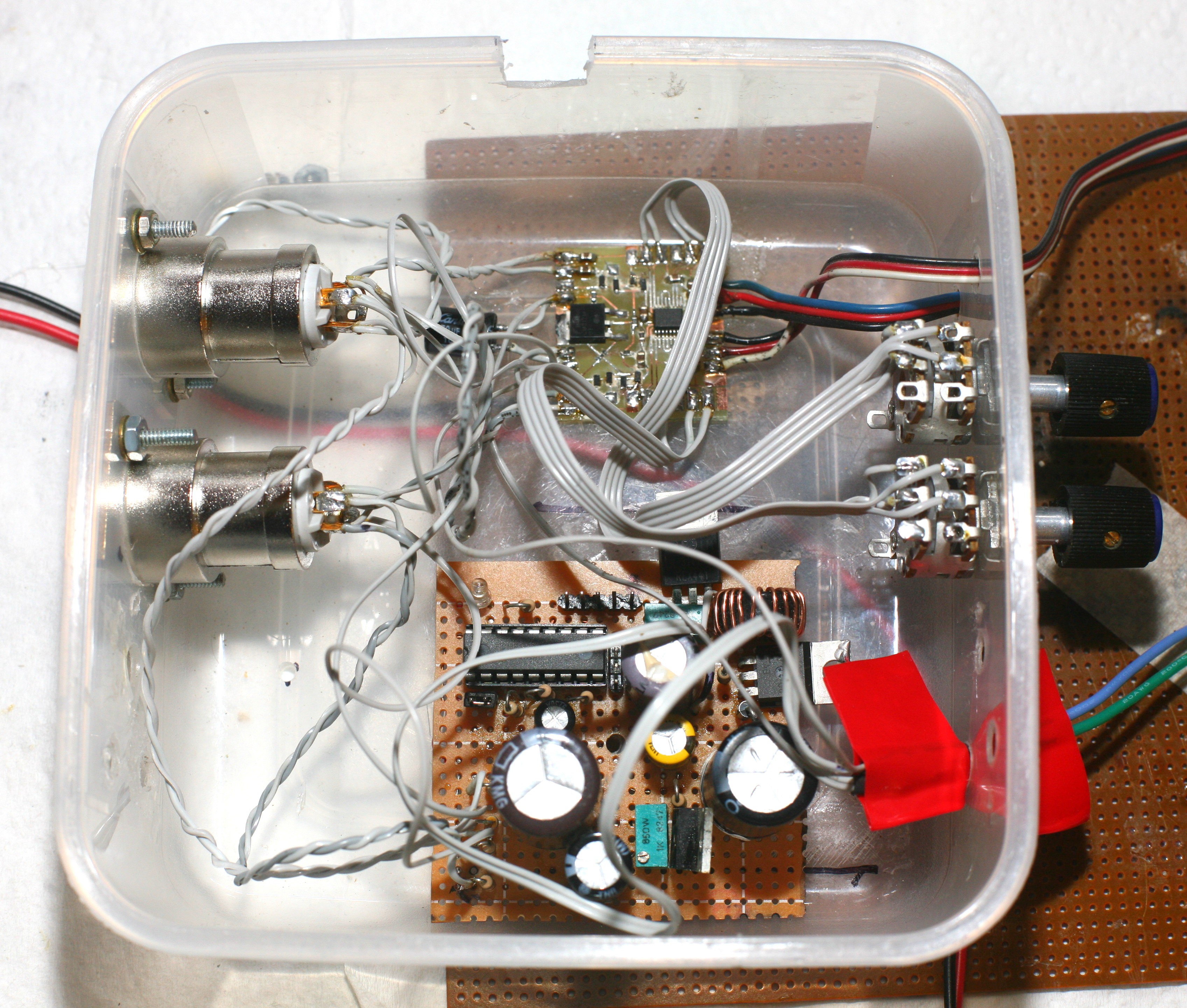
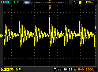
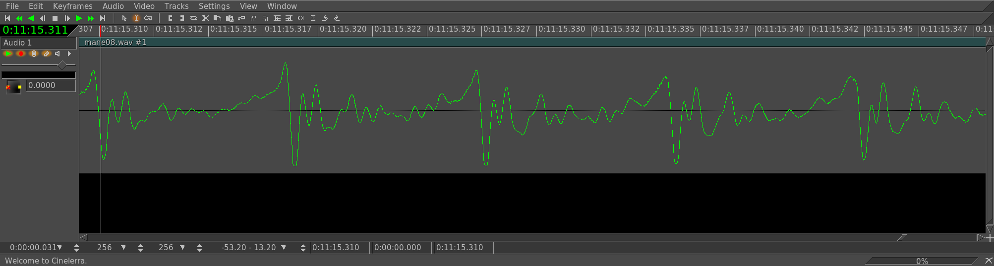
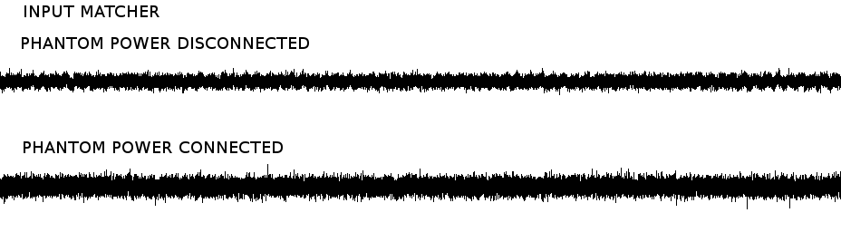
A big problem was power supply noise. It couldn't connect to the Zoom without the 2 being powered from separate batteries. It originally amplified intact differential signals from a single microphone with 2 amplifiers, then the results could be combined in software. Then it amplified a single end from 2 microphones with 2 amplifiers & threw away the inverse signals. It was all through hole because nothing could go wrong with audio, but the power line noise was a bitch.
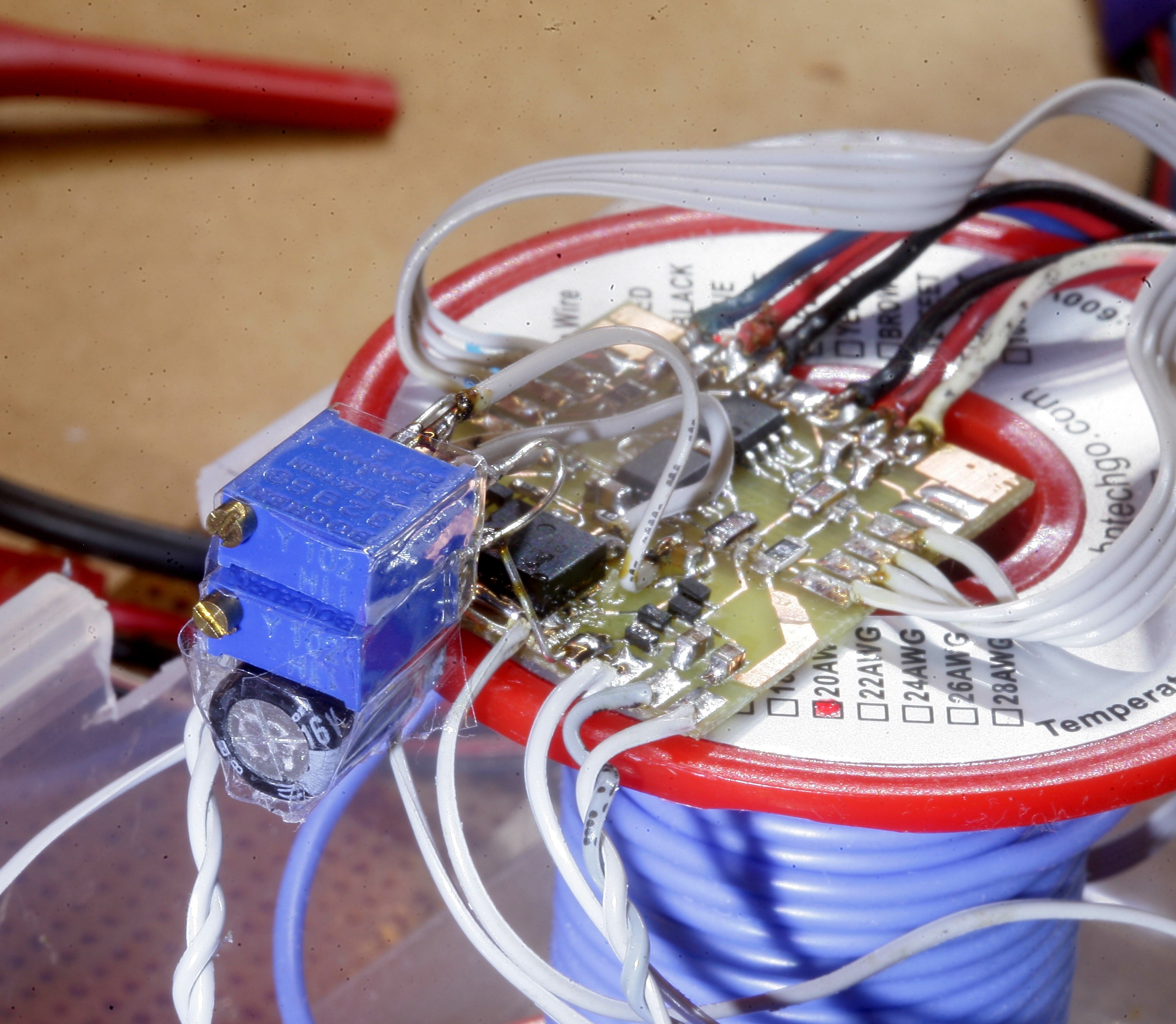
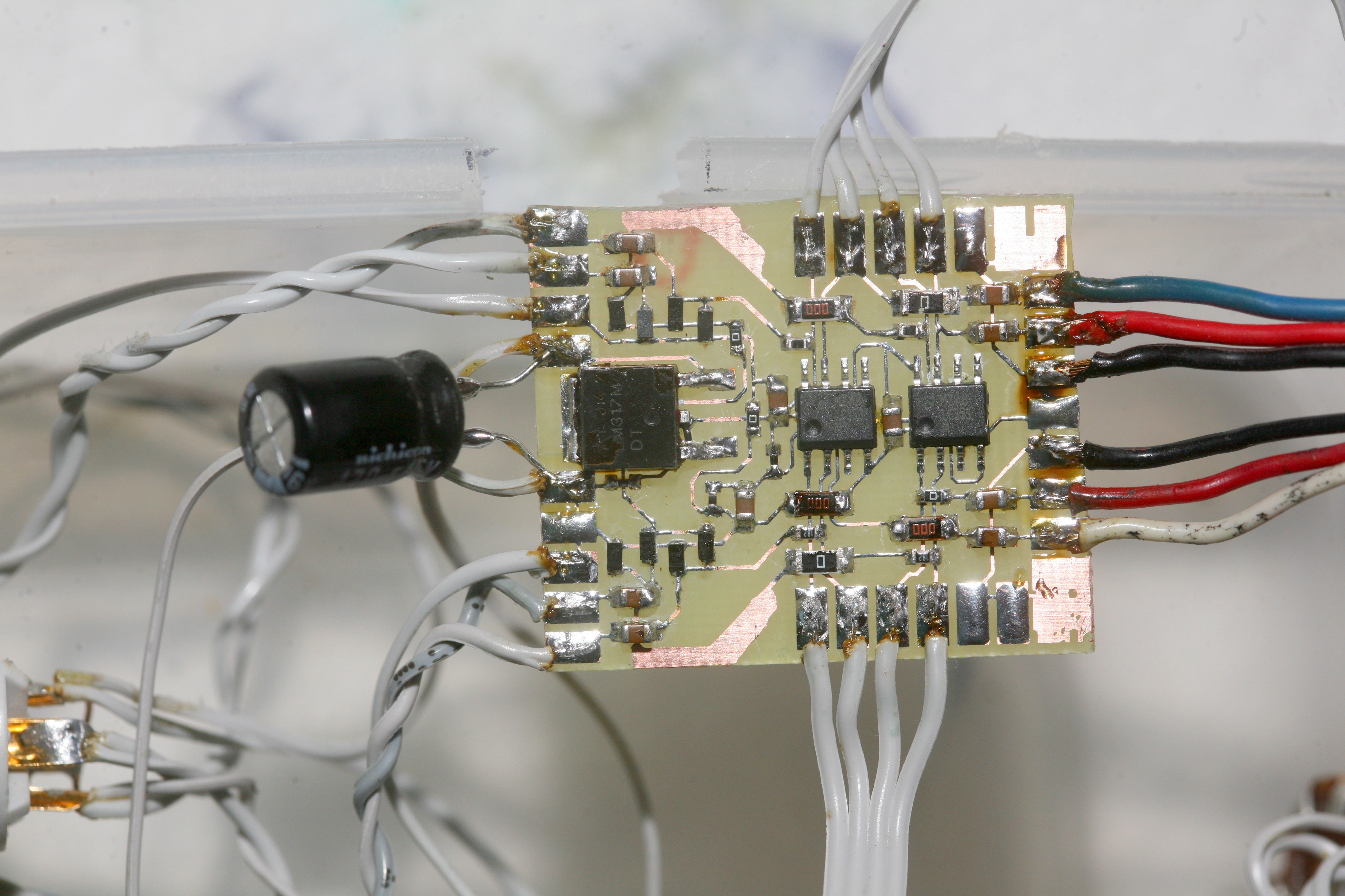
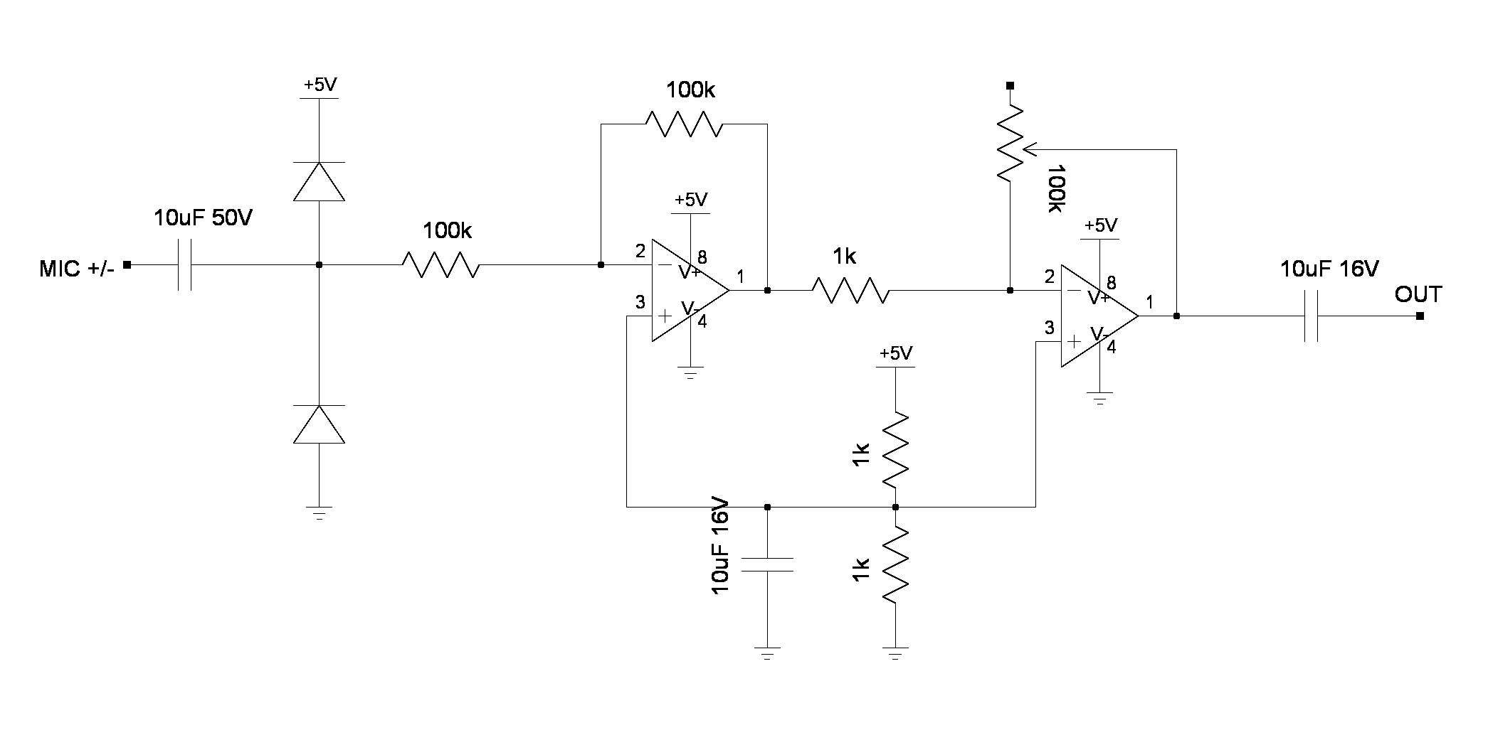
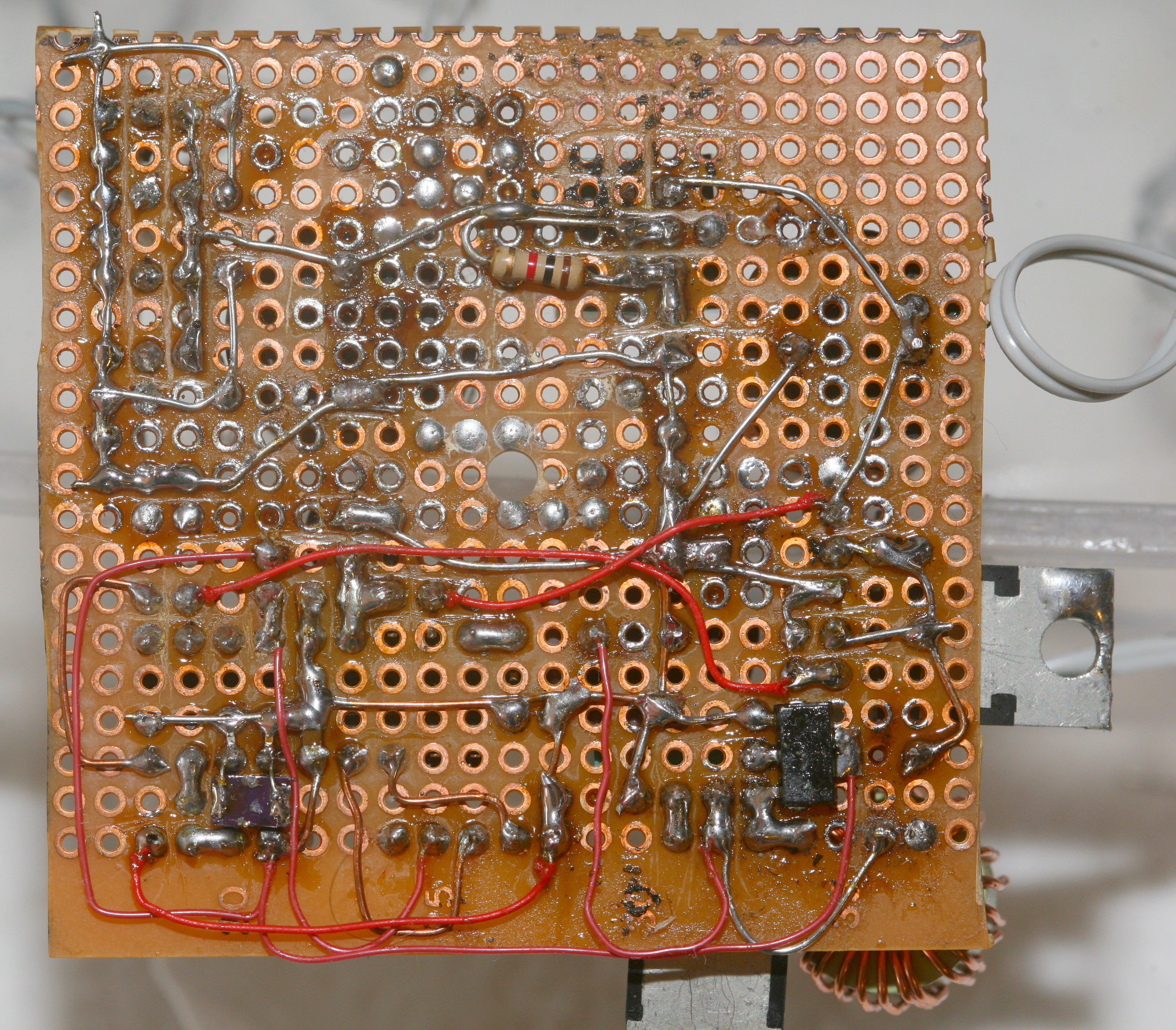
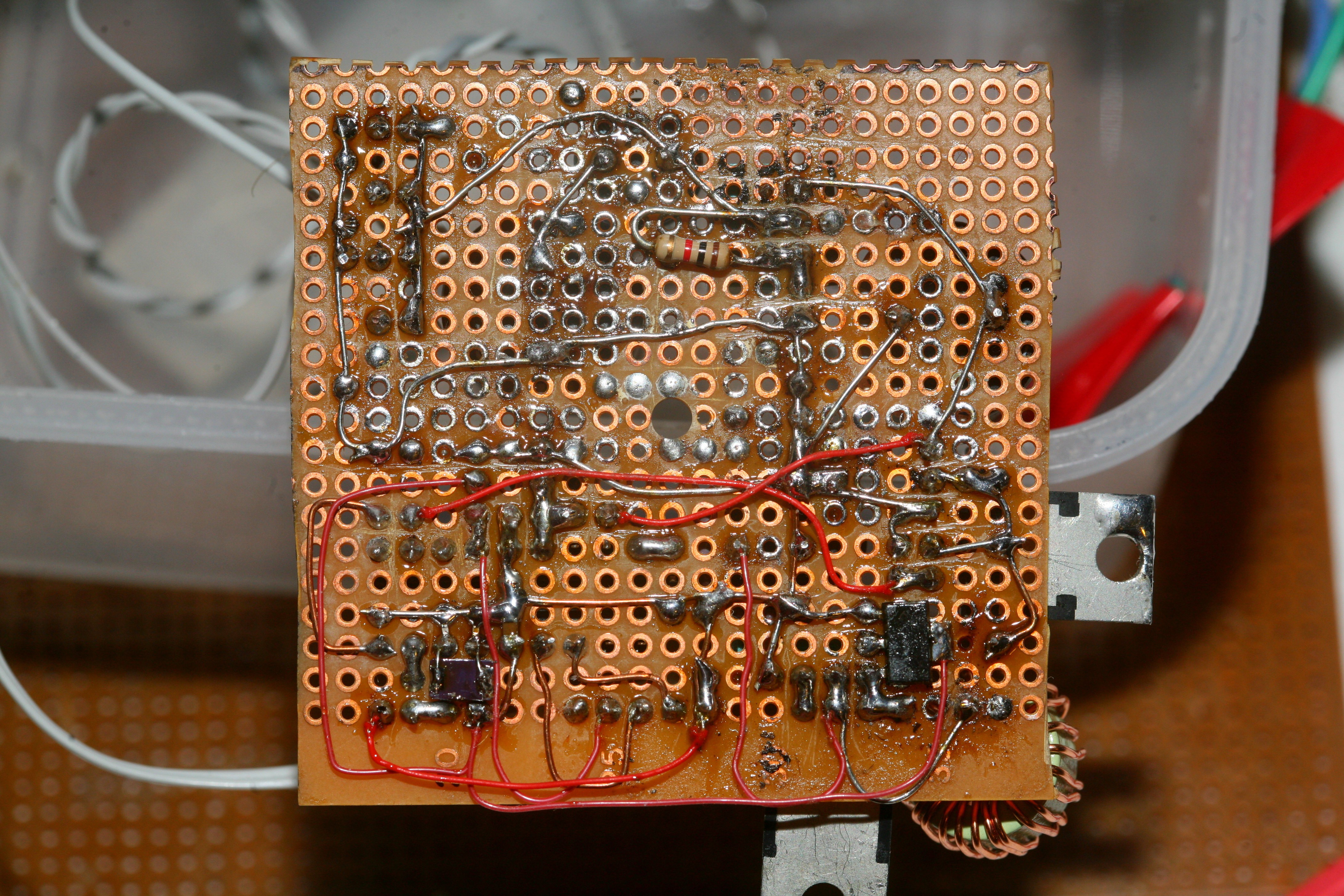
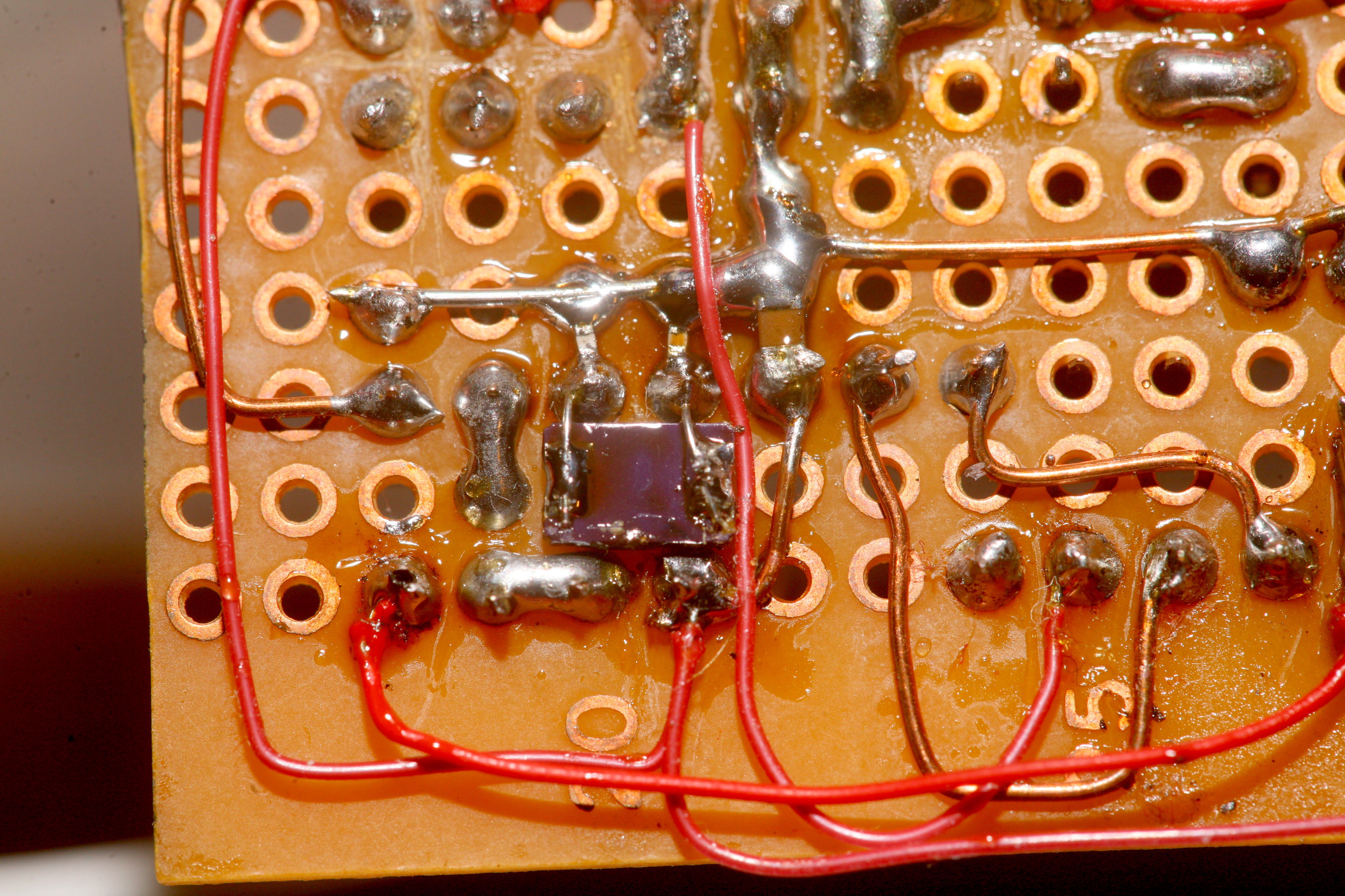
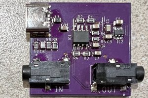
The final version amplified the intact differential signals from the 2 microphones with LF353's. This eliminated all the power supply noise & it could finally run on the same battery as the Zoom. It had some diodes to protect it from 48V & was surface mounted. There's a 5V virtual ground from a regulator.
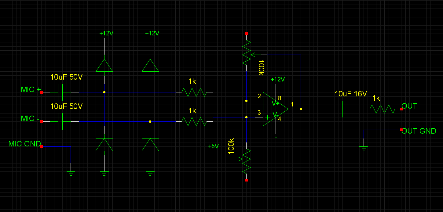
Final design of the preamp stage.
Future developments would be part of the ultimate 4 channel recorder, since the microphones were never used for anything else. Isn't it easier, more compact, & less utterly pointless just to whack a new pair of USB microphones into a raspberry pi? Of course it would. Even the 24 bit 96khz of an external preamp probably can't compare to digitizing right up against the capsule. Maybe there was a belief a better analog microphone would come along or it would be like vinyl.
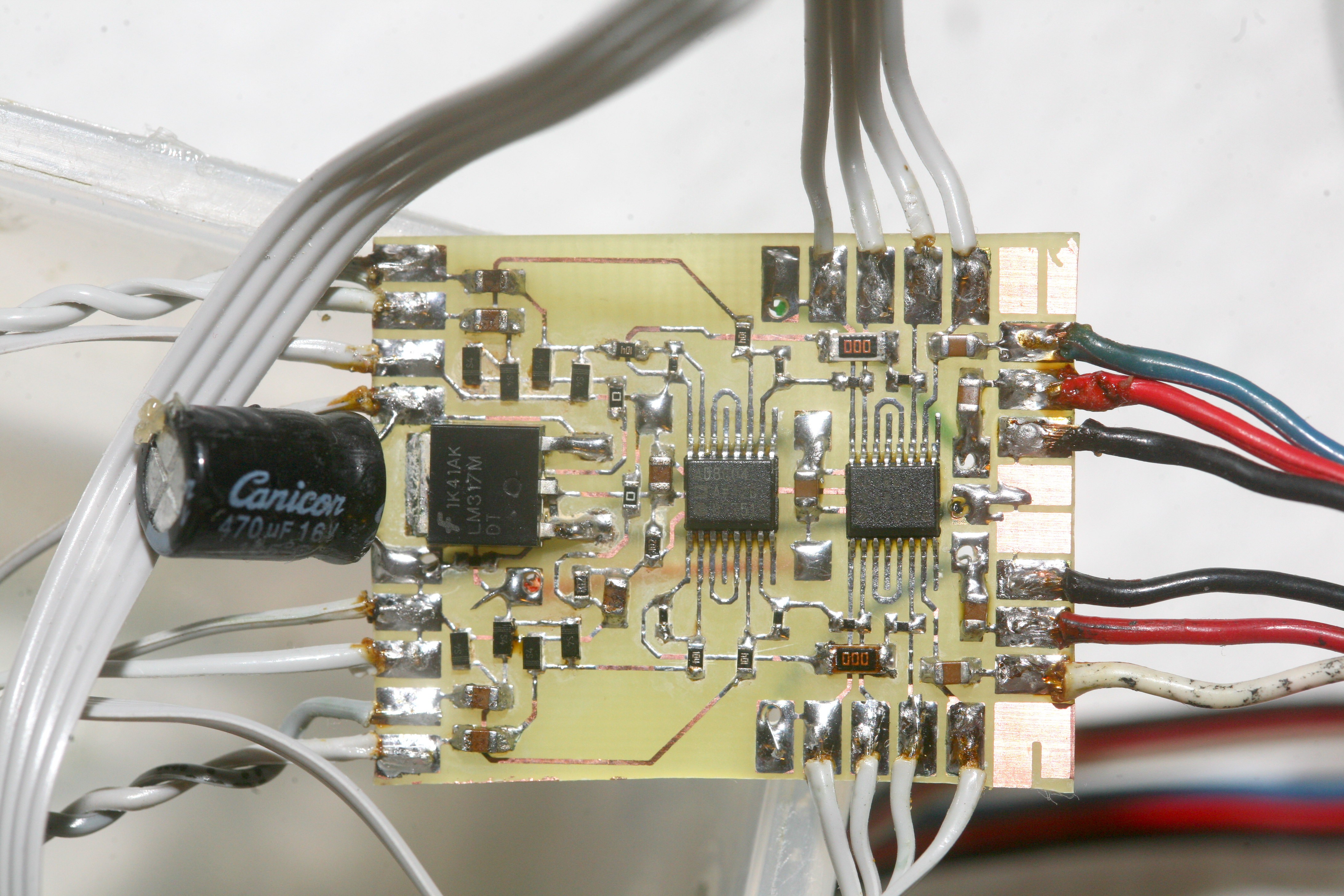
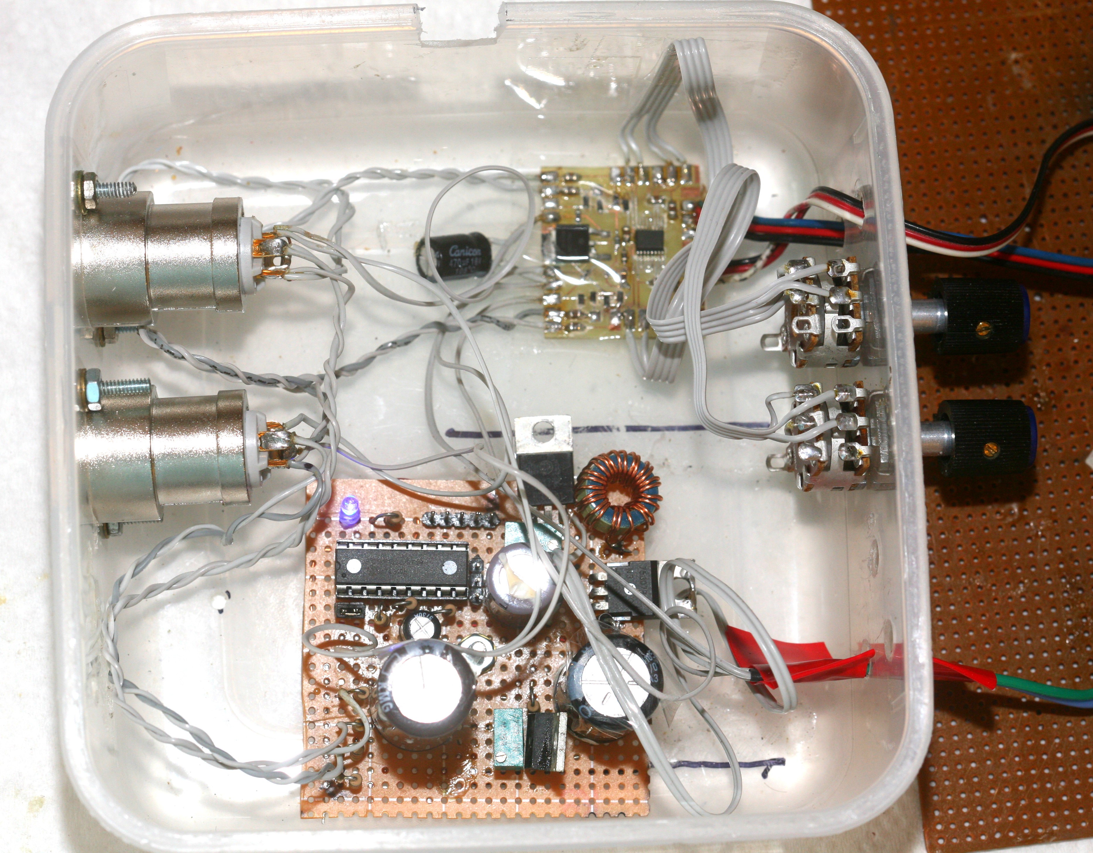
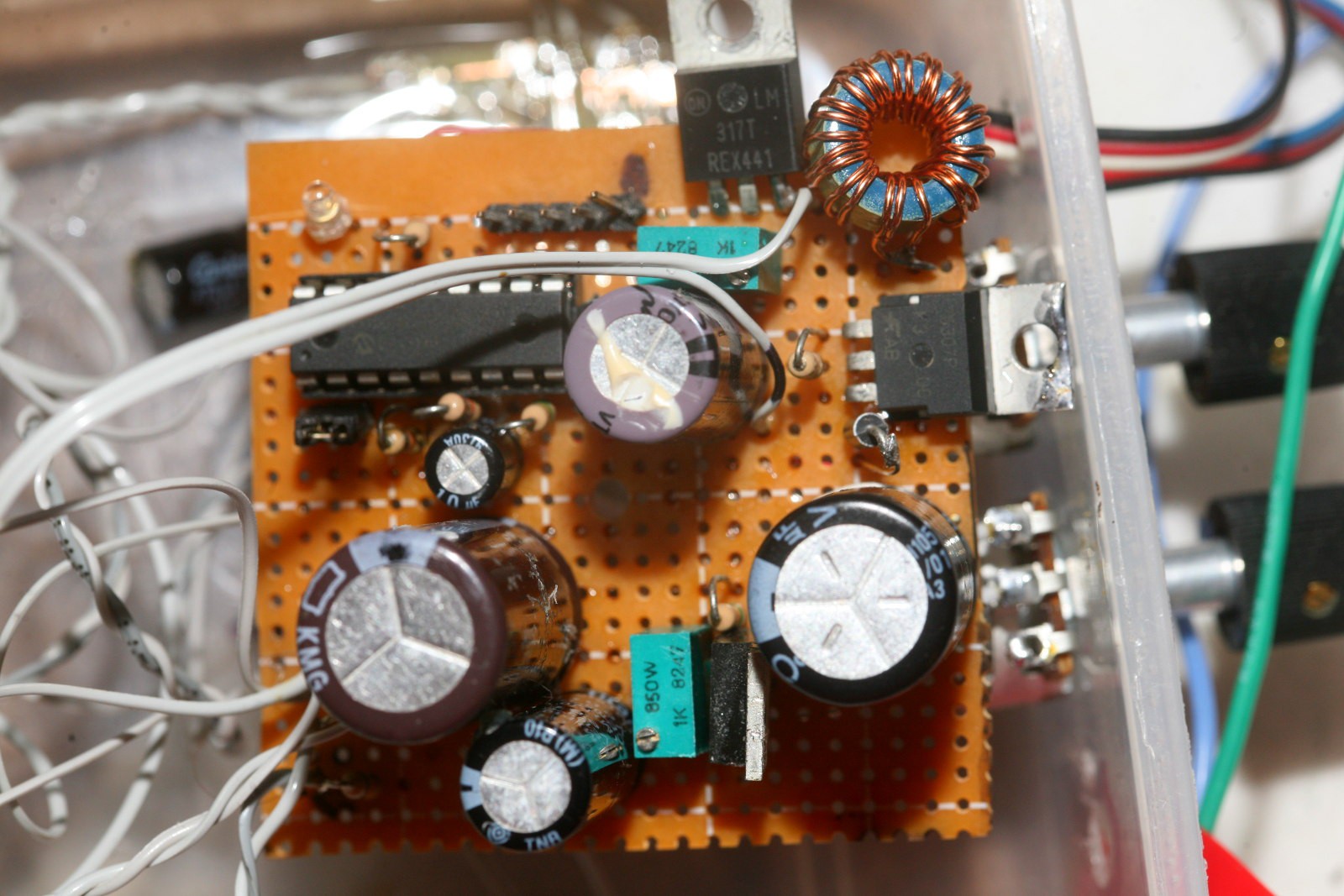
A revised design in 2018 was much more efficient.
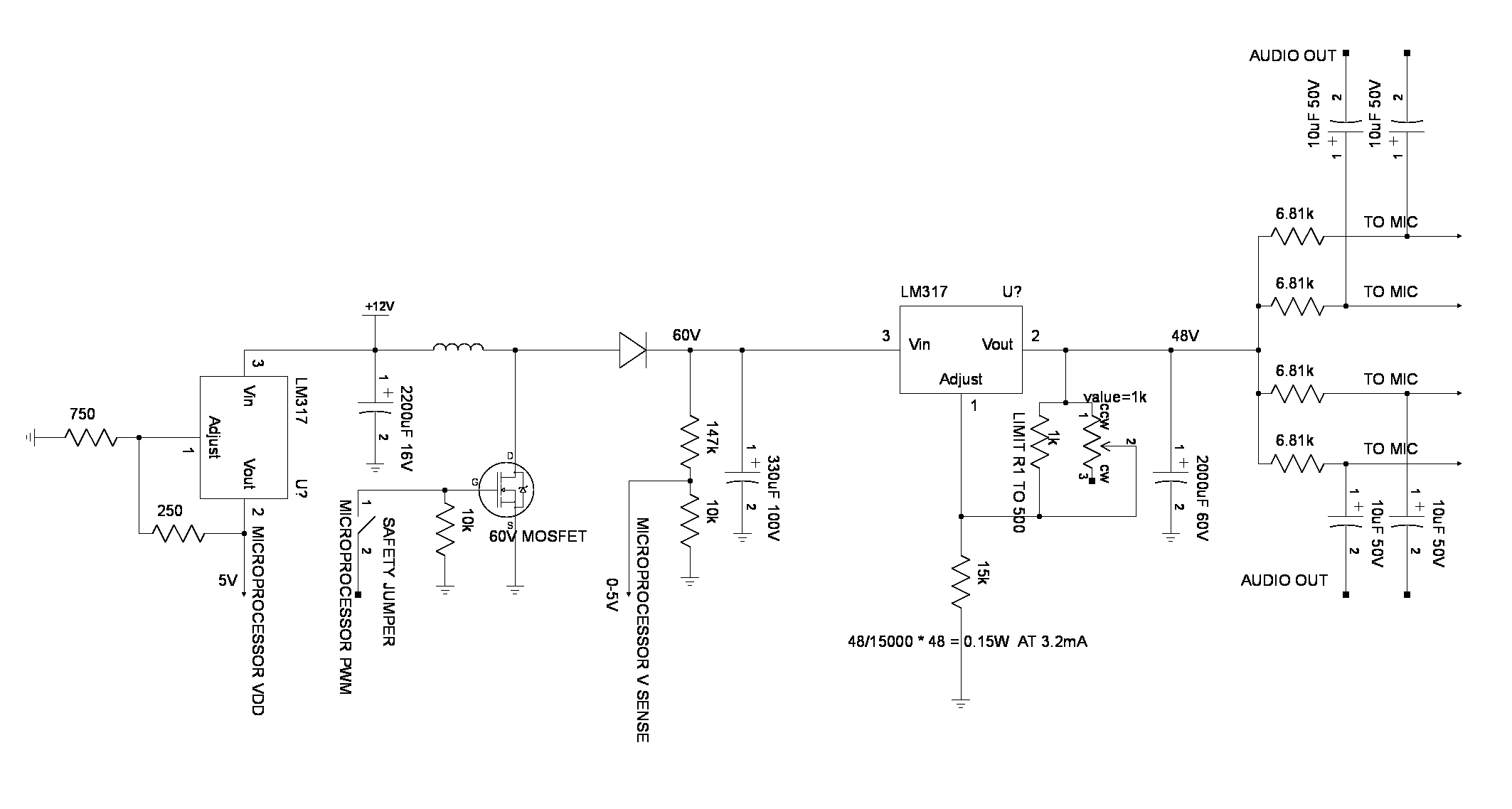
The new boost converter used a linear regulator to drop an unstable 50-60V to a stable 48V.
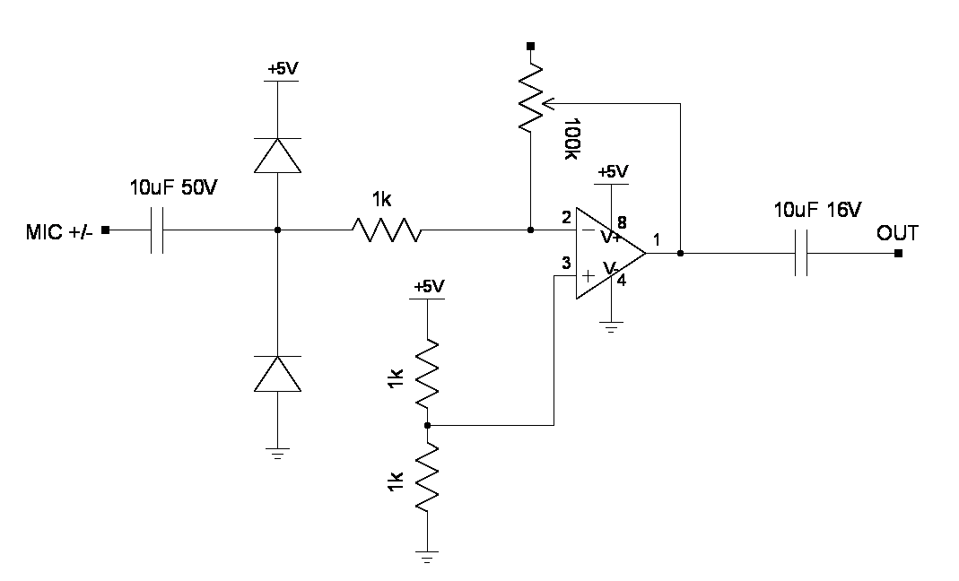
The new amplifier section was just 4 inverting amplifiers. The input resistance is too low, but it's good enough. Minimizing noise & harmonic distortion on such a circuit can be an obsession.
https://cdn.hackaday.io/files/292031249421152/mane.c
New but extremely simple booster firmware handled the newer voltage.

 Nick Sayer
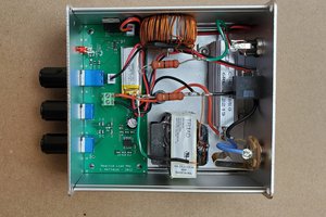
 Collin Matthews
 Szoftveres