 Sebastian Lenartowicz
My primary goal for this project is to build a functional 3D printer for less than $150 (not including filament), but I really want to try and do it for less than $100. I'll be keeping a tally in the parts section, and a grand total here.
The whole thing is made more complicated by the fact that I don't have access to any real machining equipment or an existing 3D printer (so far as I'm aware), so I have to build everything using no tool more complex than a dremel or soldering iron. Oh, and I've never built a 3D printer before, so I'll be learning everything as I go.
On the upside, my university throws out a ton of awesome scrap, including functioning computers, and this is likely to be one of my primary sources for parts.
TOTAL COST SO FAR: $2.30
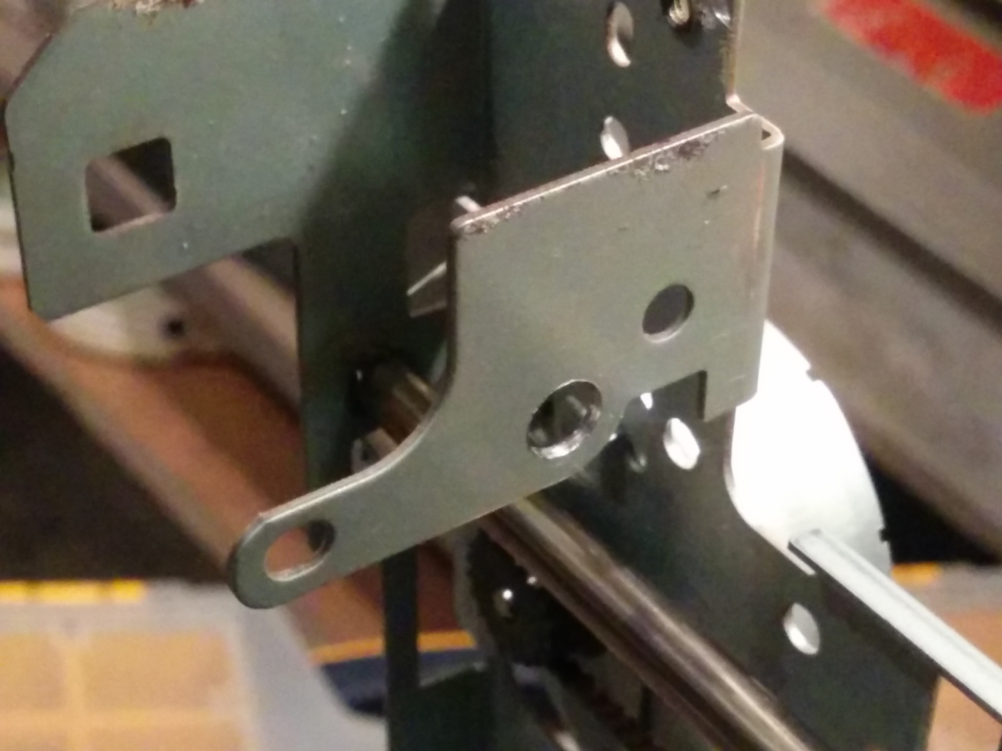
 out the bit marked with Sharpie in the bottom left, with the idea that I would use the protruding cylindrical bit as a second slider on the new rail.
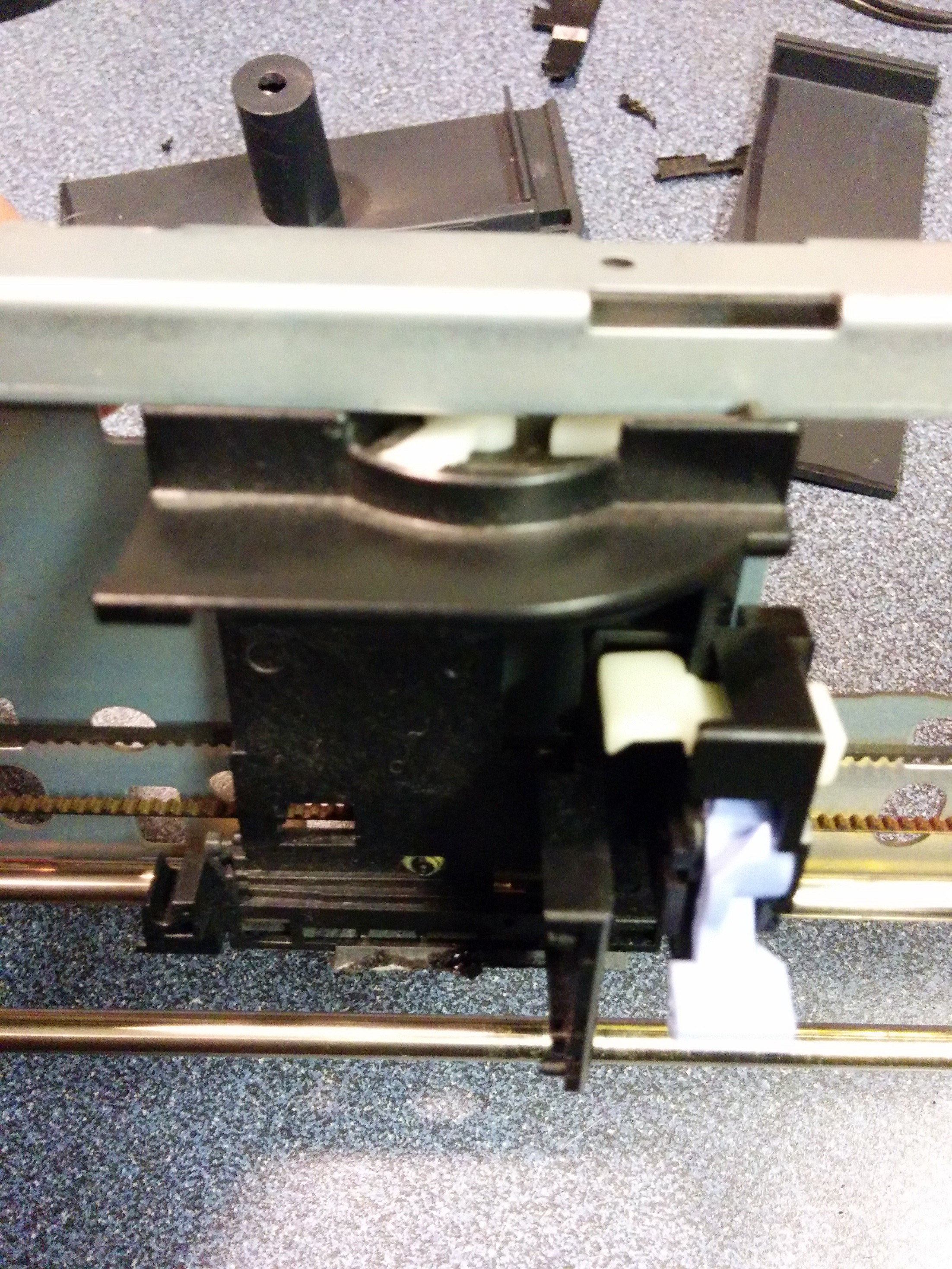
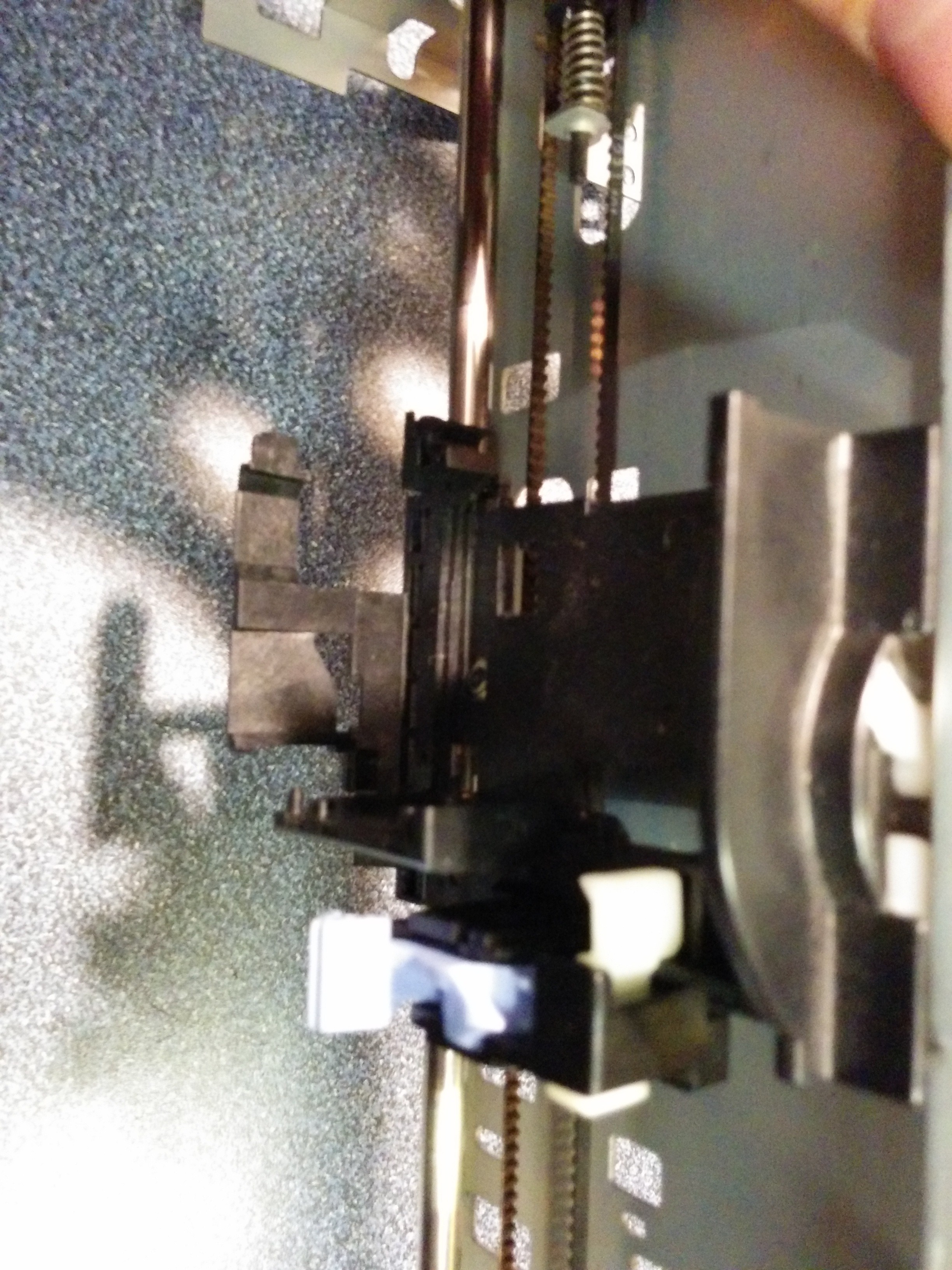 After cutting it to the right size (I just rough-cut it from the plotter end-cap), I realized that the best way to mount the new piece was to use some long M4 bolts, with a couple of nuts between the protruding element and the slider acting as standoffs (because the protruding element has an uneven surface, mounting it directly wouldn't work very well, and I wouldn't be able to do a good enough sanding job to make it work because it's made of ABS and would melt rather than grinding).
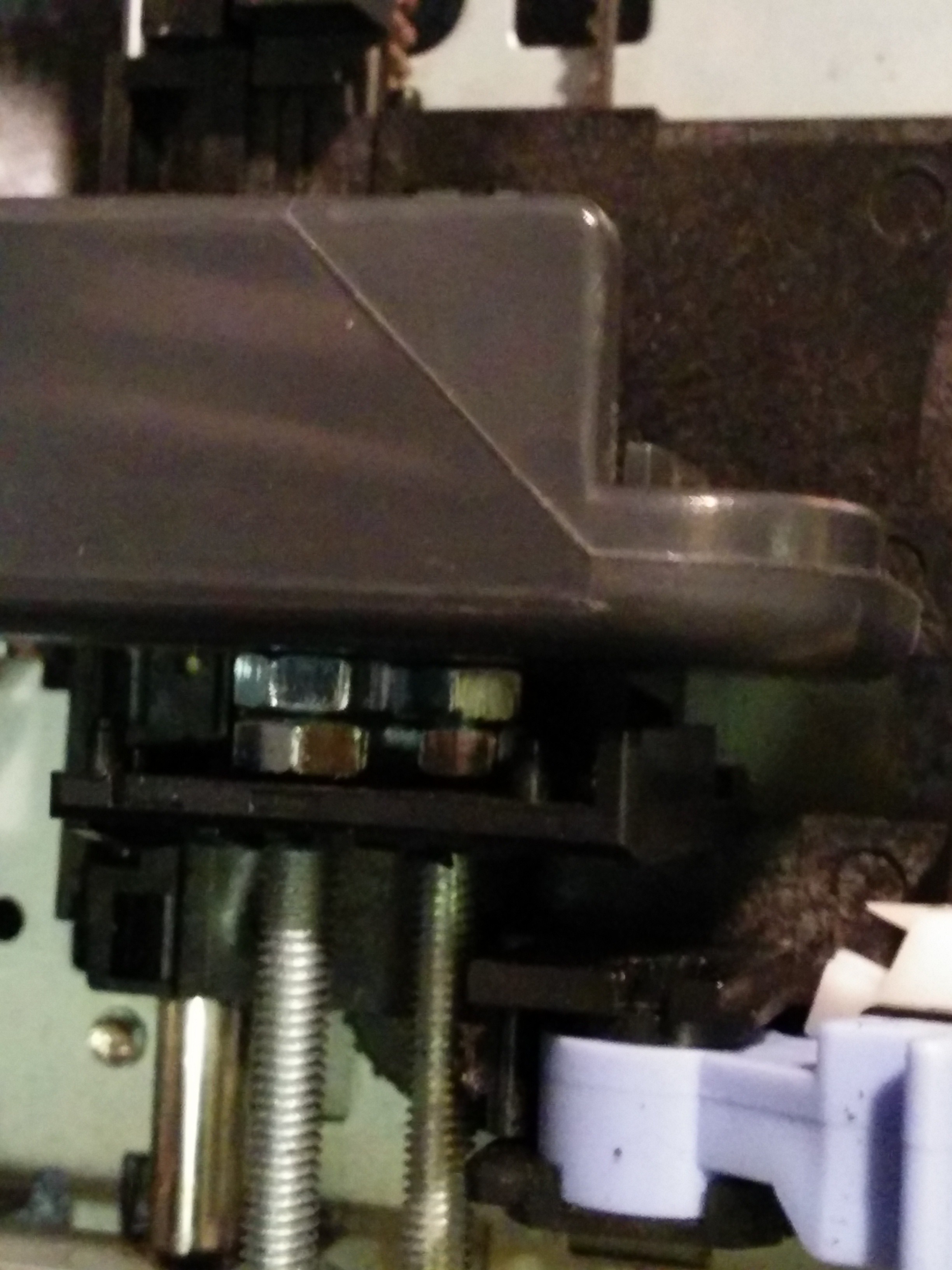
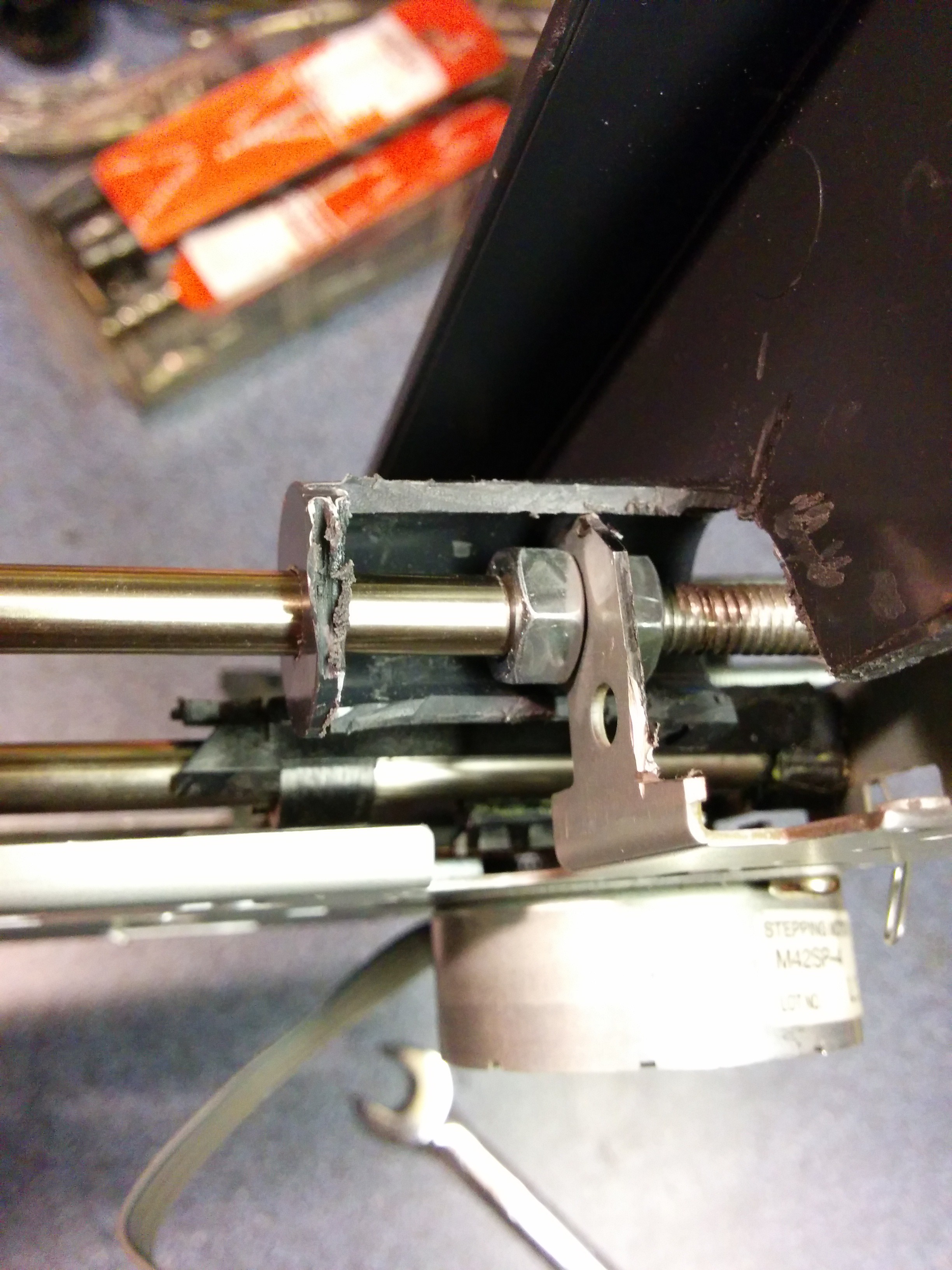
 The first, and biggest, problem is the wobble in the print head itself - the way it's designed, it uses only a single rail and the force of gravity to keep it stable and on target relative to the paper. This is unacceptably error-prone when it's being used for a 3D printer (as it will be moving around in more than one axis, and might jerk around and move off-target as it's being adjusted in the Z-axis).
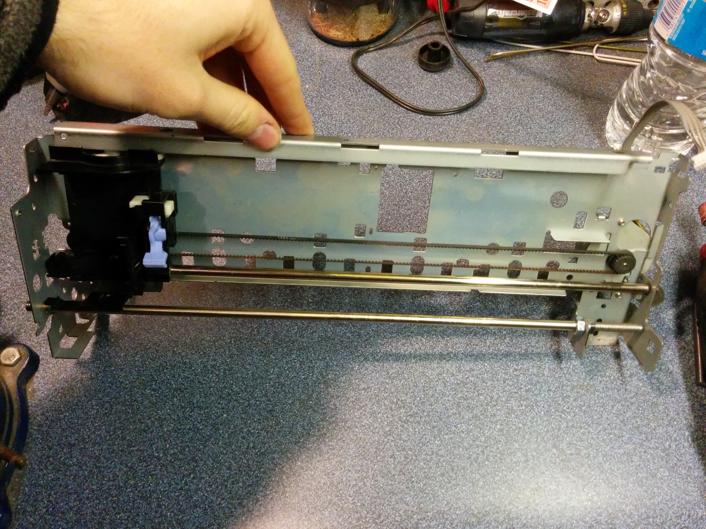
 It has a shorter travel distance than the Z or Y axes, but I figure the light weight is worth the tradeoff. My one possible concern is that the datasheet for the stepper lists it as having an angle change of 7.5 degrees/step, though whether that will be an issue remains to be seen.
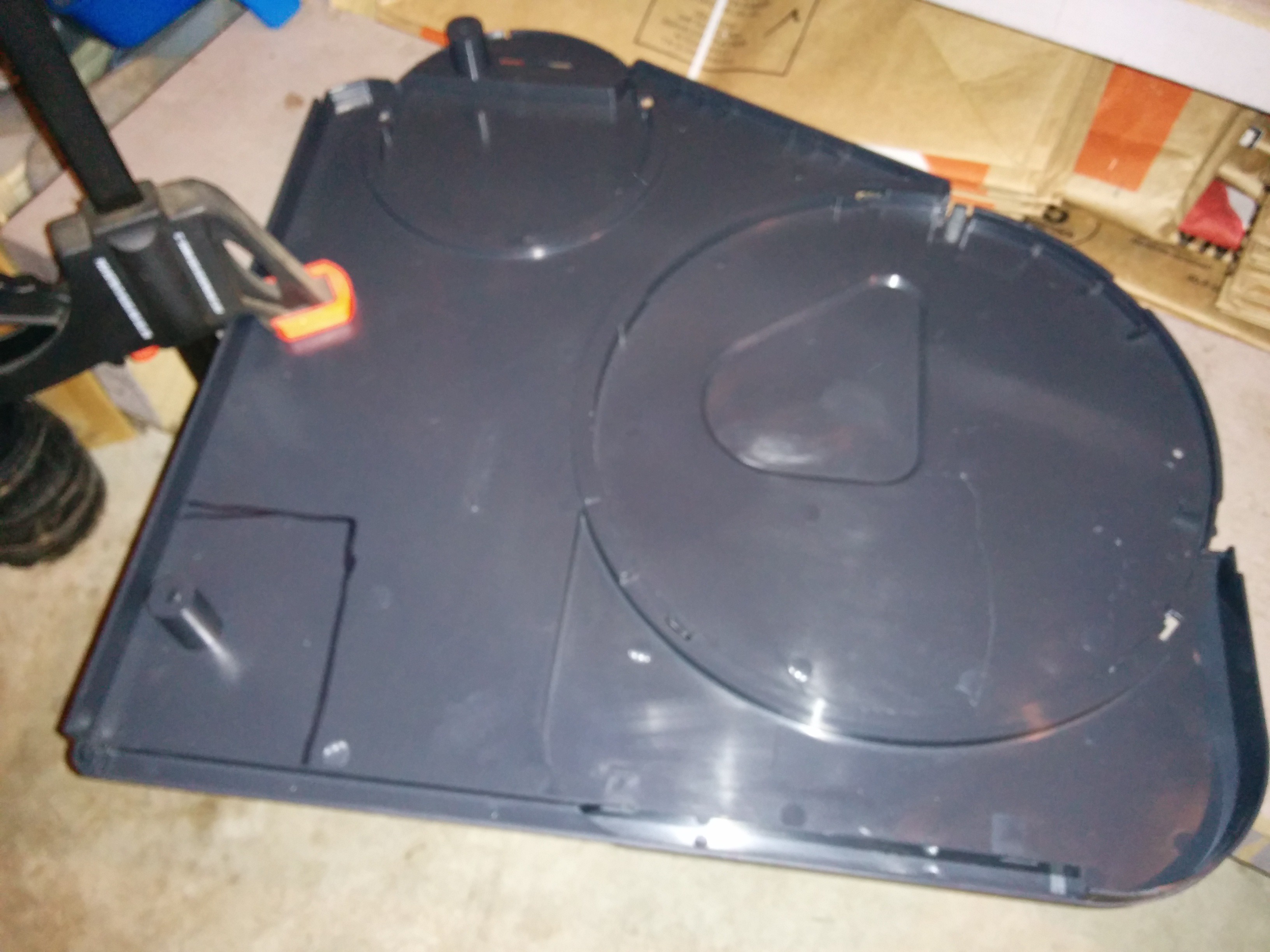
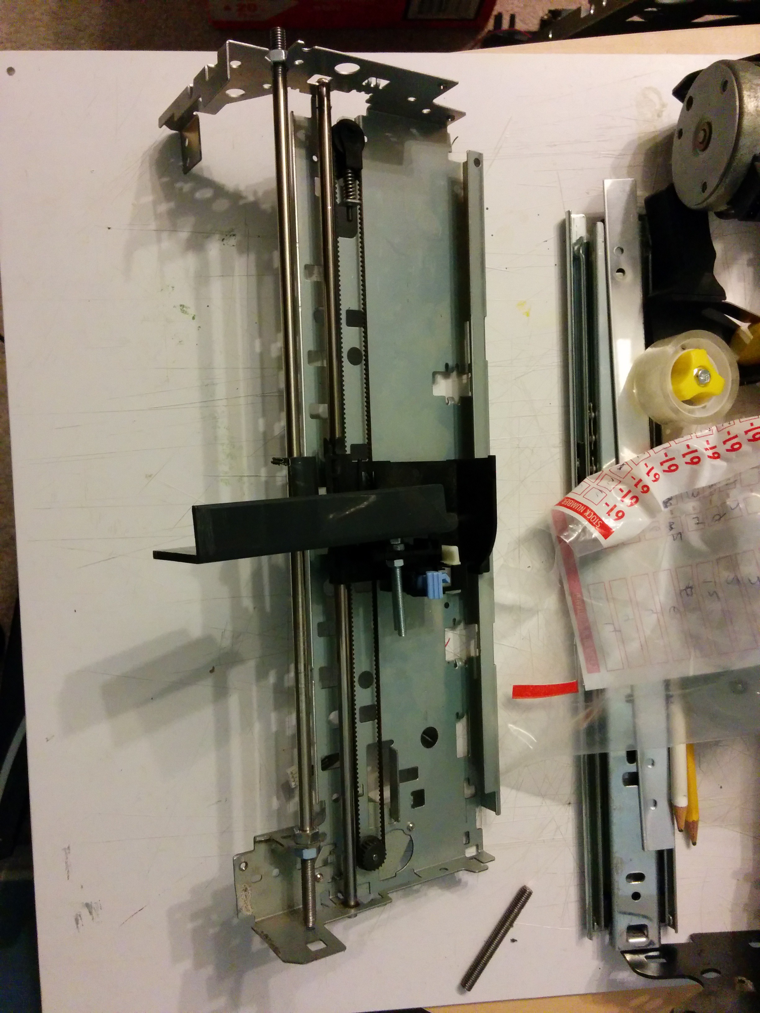
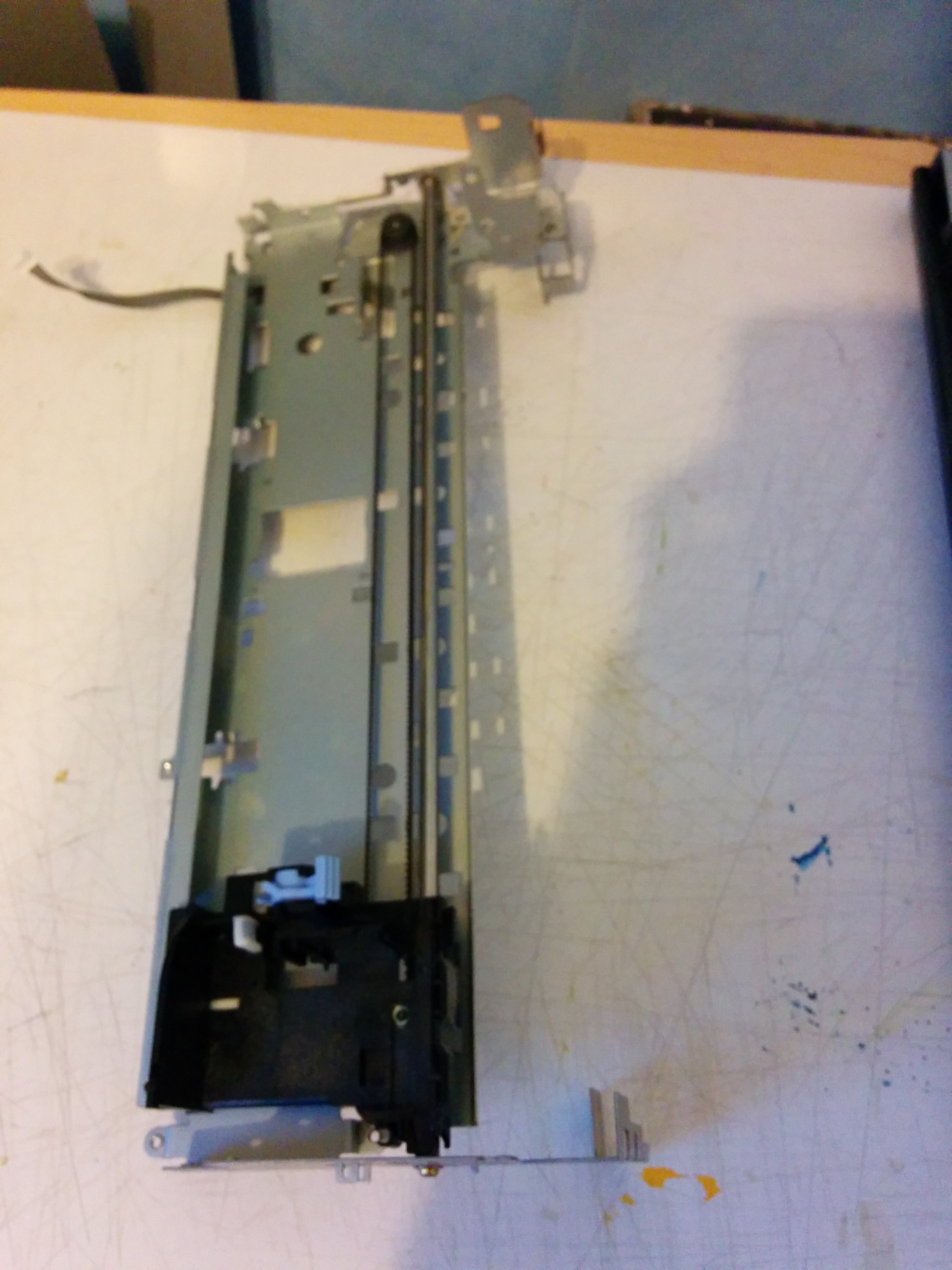
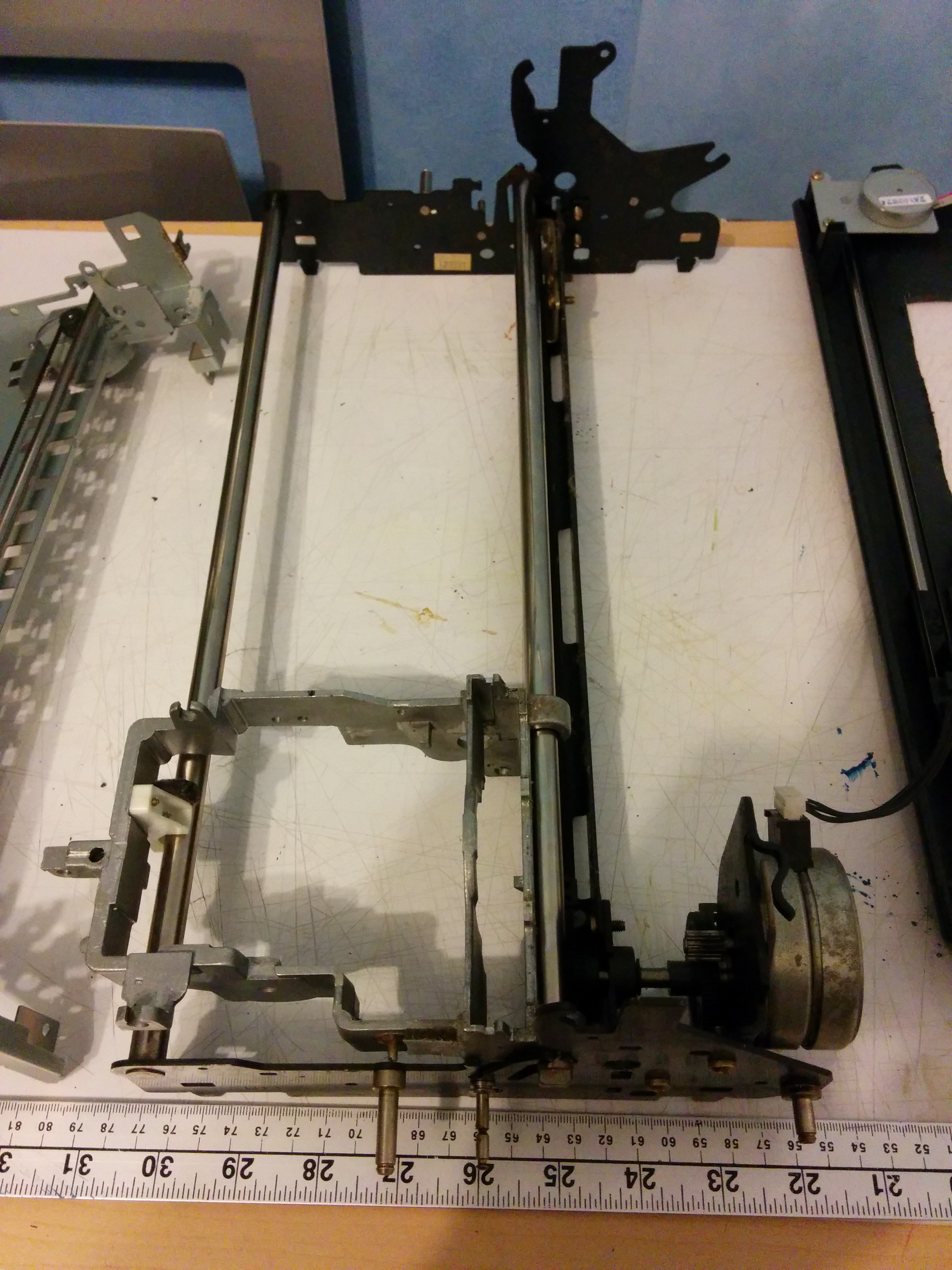
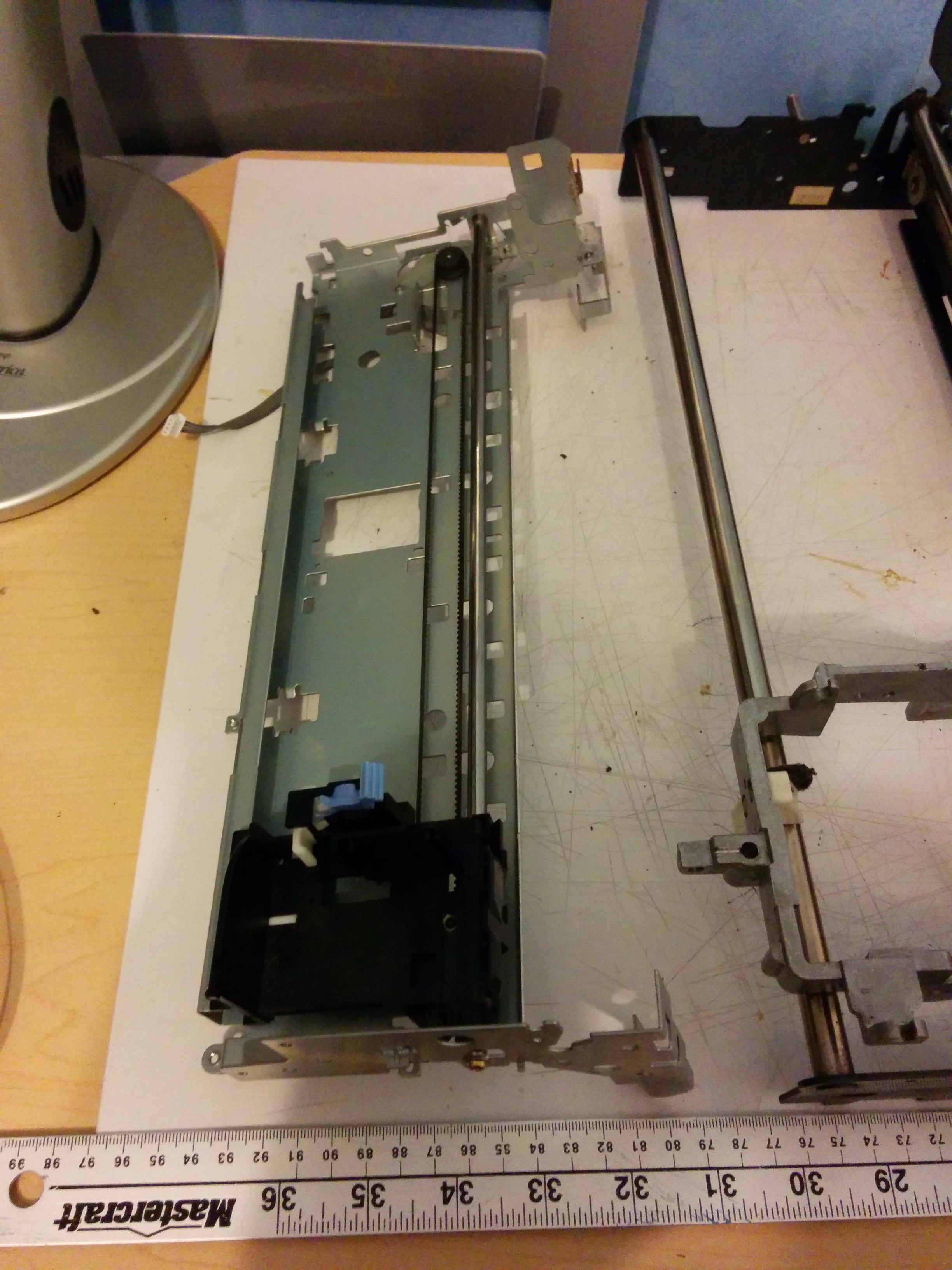
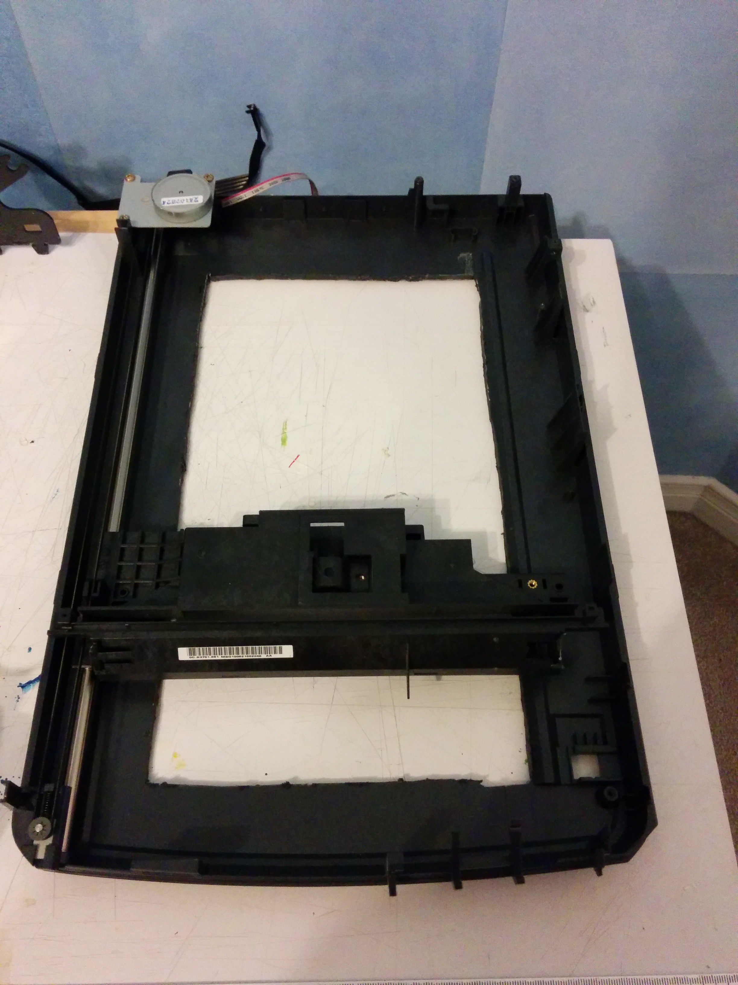 the Y-axis will be built from this: a dismantled Epson flatbed scanner (left). This model has a high maximum scan resolution, which leads me to believe that the stepper will be relatively precise. The current idea is to use brackets and bolts to mount the bed to the scan head (which has been completely dismantled, with only the plastic housing left behind). The scan head itself runs using a stepper and timing belt on one side (left in the picture) and a small wheel on a raised plastic ridge on the other. Whether the motor will be able to hold up to the rigors of 3D printing remains to be seen. And, yes, that is a hole in the bottom, cut when my design idea was for an XYZ-together printer (I was going to mount the extruder on the scan head). Now I figure it'll save some weight and make it a bit easier to see what I'm working on when I'm building it.
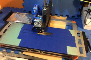
 ken.do
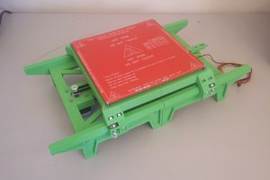
 TTN
TTN
 heinz
heinz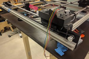
 Nikolai Ovesen