 Stefan Lochbrunner
Initially I planned on building a very basic case out of two pieces of acrylic in the style of the Dangerous Prototypes Sick of Beige cases but then I picked up one of these mini cigar tins. (yes, that picture AGAIN)
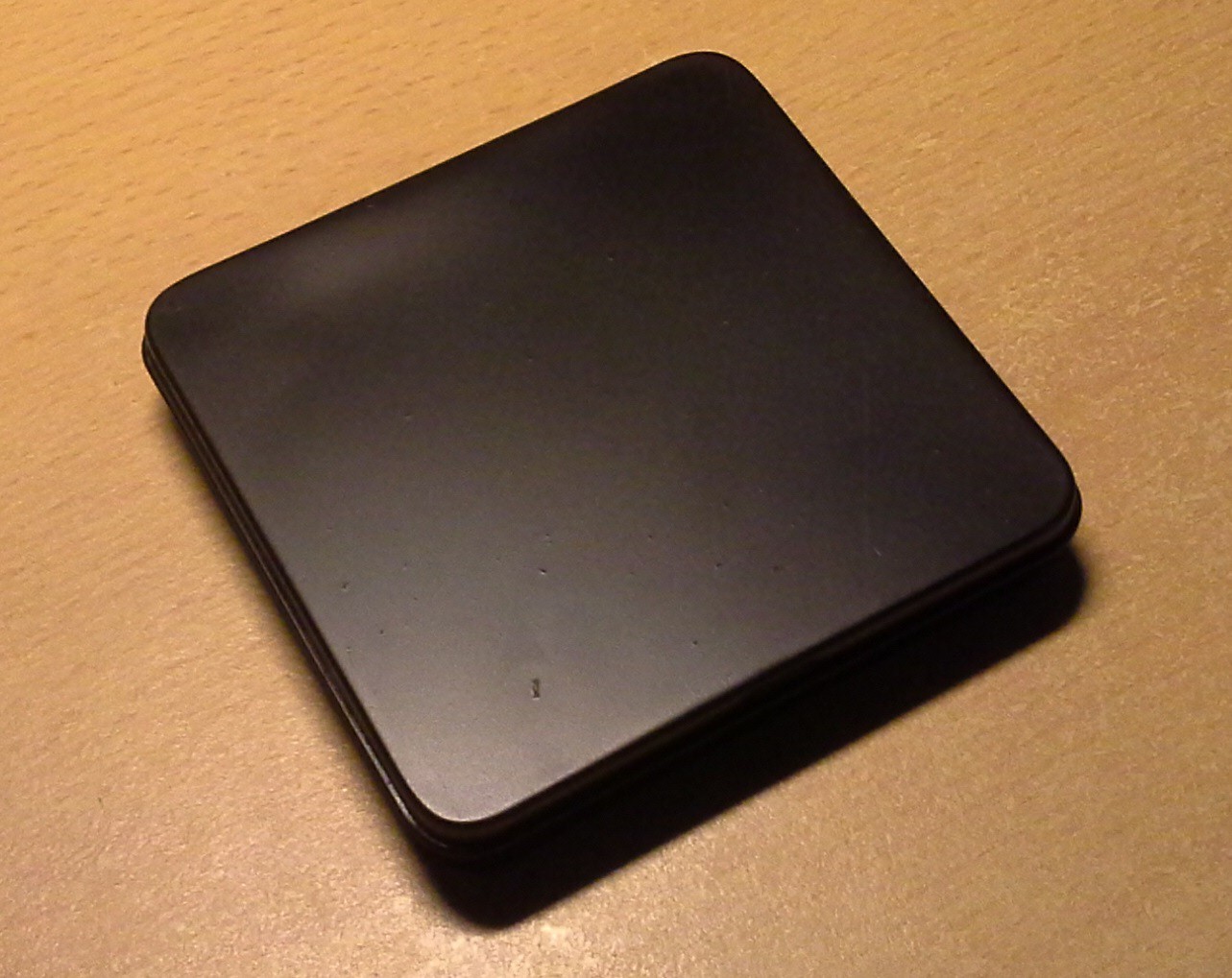
It's about 92x89x18 mm so I figured it would be about the right size for the amount of buttons and would have enough space for the components.
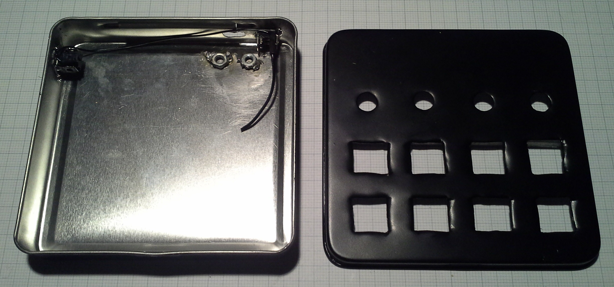
The idea was to mount the buttons and rotary encoders to a perfboard (as seen in a previous log) and mount that board to the lid of the case while the MCU and other components are mounted to the main body of the case. From the perfboard with the buttons and encoders I transferred the positions of the required openings to the lid and cut them out or drilled holes to the required diameter. Since the openings in the main body didn't have to fit precisely over buttons (and USB port) but instead the buttons could be aligned to the holes I just eyeballed those holes and ended up with this:
During test fittings I realized that I'd run out of space in the back of the case where the MCU should be placed. I would have liked the keyboard part to be detachable via some pin headers but to make it work I decided to permanently solder them together like this:
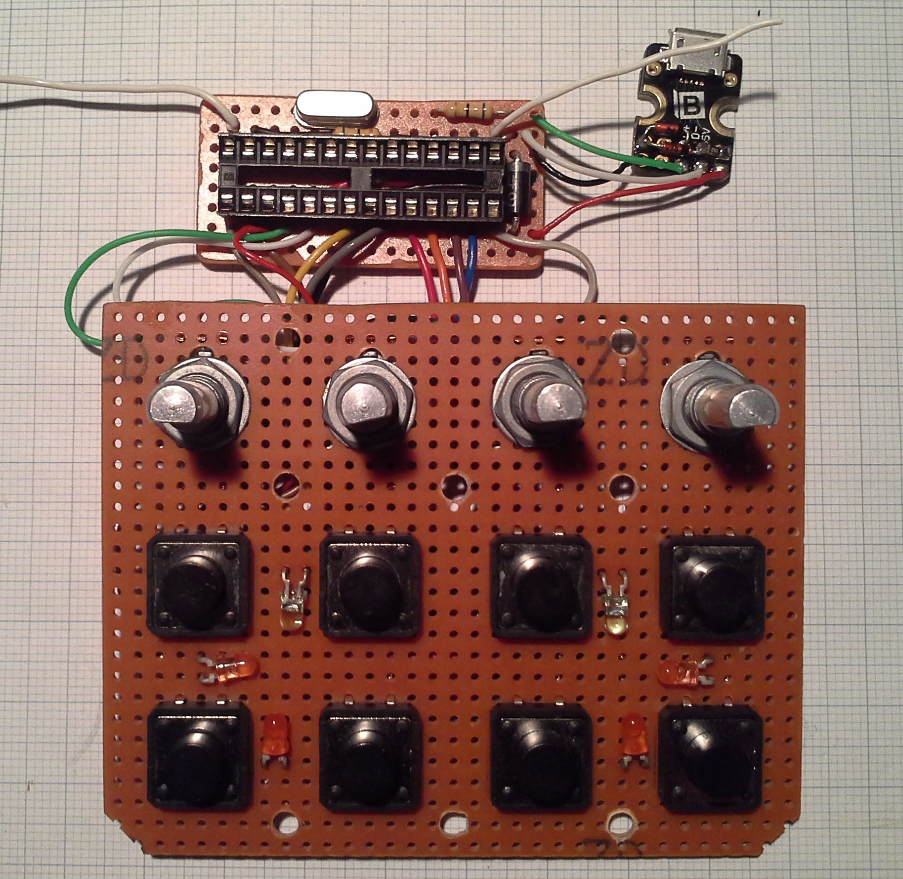
Due to these spacial constraints I had to omit mounting points for the MCU board as can be seen in the image of the bare case and the board itself. With the bottom of the perfboard isolated from the case with a sheet of plastic and the wires pressing against the board it is safely (enough) "mounted" in the case such that it won't move around.
Note: It might look like I'm missing some components for the Pro Trinket circuit such as filter capacitor, reset pull-up resistor and so on. To save space I used mostly SMD components and through hole where I wanted to bridge a longer distance. This time I even included the capacitors at the crystal ;) The two white wires are connected to the reset and mode buttons in final assembly.
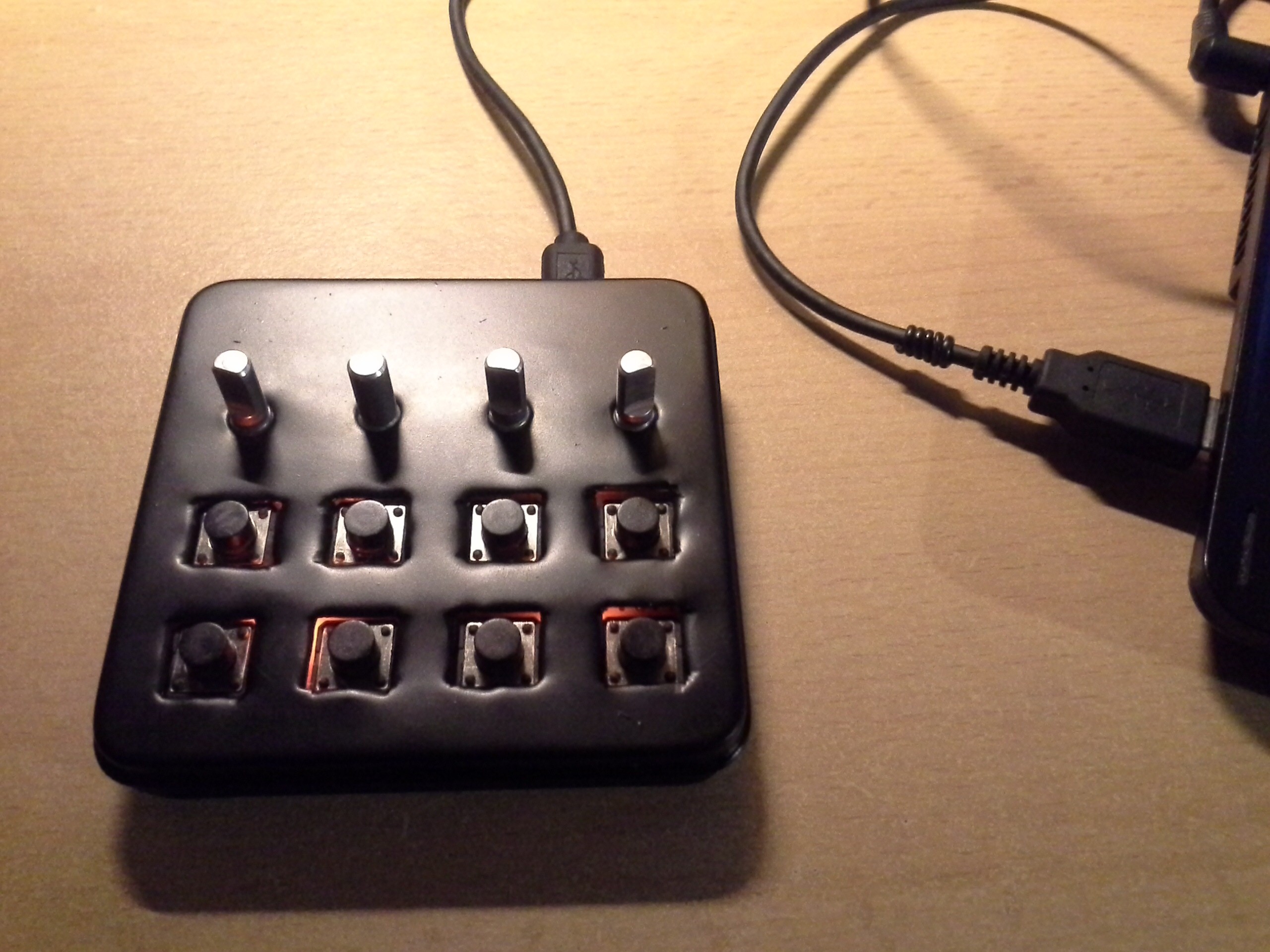
Next I super-glued some spacers to the lid to which the keypad is attached.
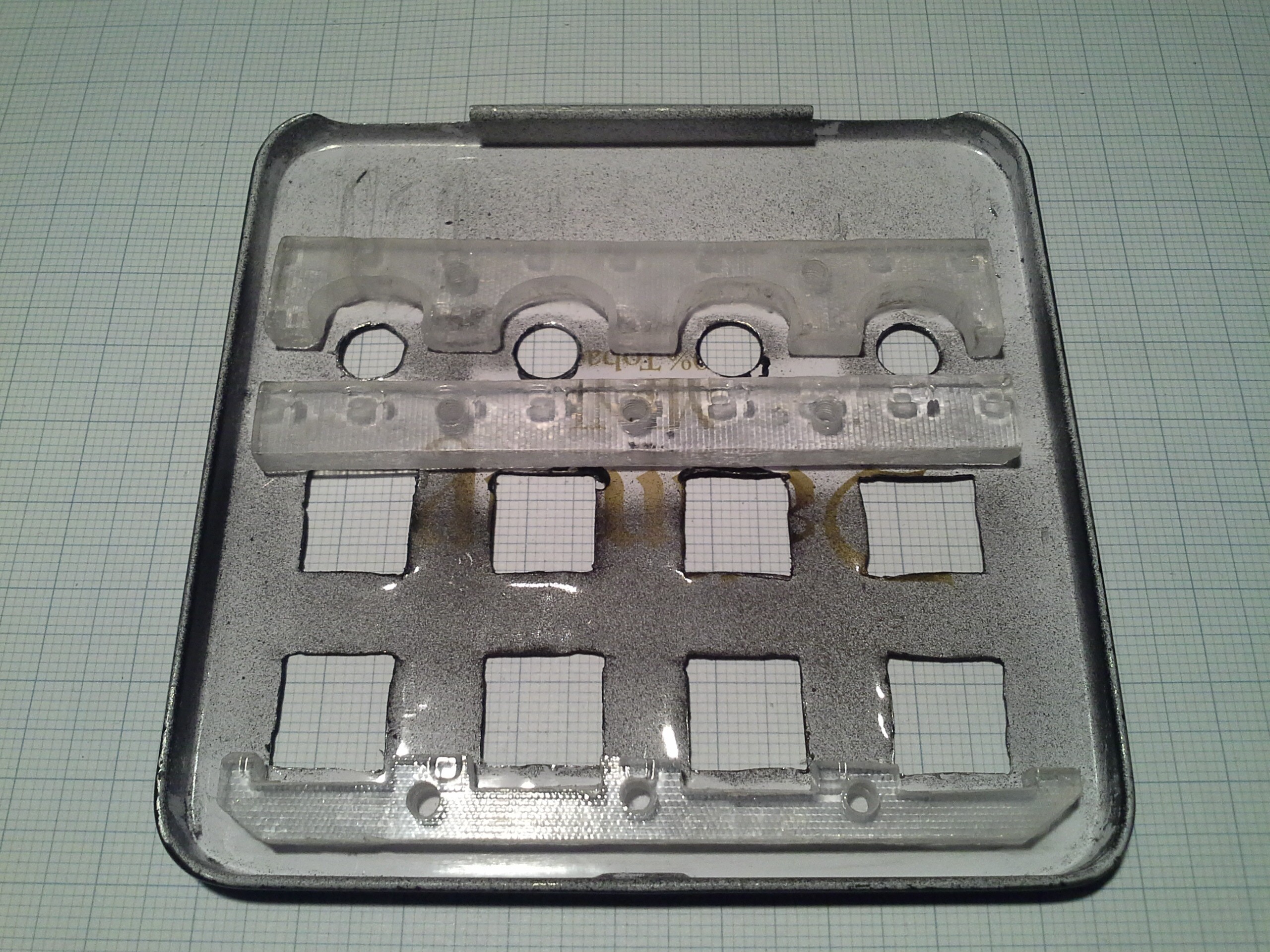
The spacers are a little thicker than the body of the tact switches such that there will be a gap through which the backlight can be seen from the outside.
To finish it off the keypad is screwed onto the lid, the micro USB jack is mounted in the case and when closing the lid care is taken to keep the MCU board in place.
And that's it.
Discussions
Become a Hackaday.io Member
Create an account to leave a comment. Already have an account? Log In.