Tim
Tim-
Final EDC Contest Update!
01/02/2015 at 15:14 • 0 commentsI'm wrapping everything up for the EDC contest today. I just changed the project name to 'Robotic Third Hand' instead of 'EMG Third Hand'. I"m not sure if that is going to break any links or mess up my entry, hopefully the omniscient hackaday staff has got that all under control. The EMG just didn't make sense to keep in the name since I found the EMG part not fit for the spirit of this project.
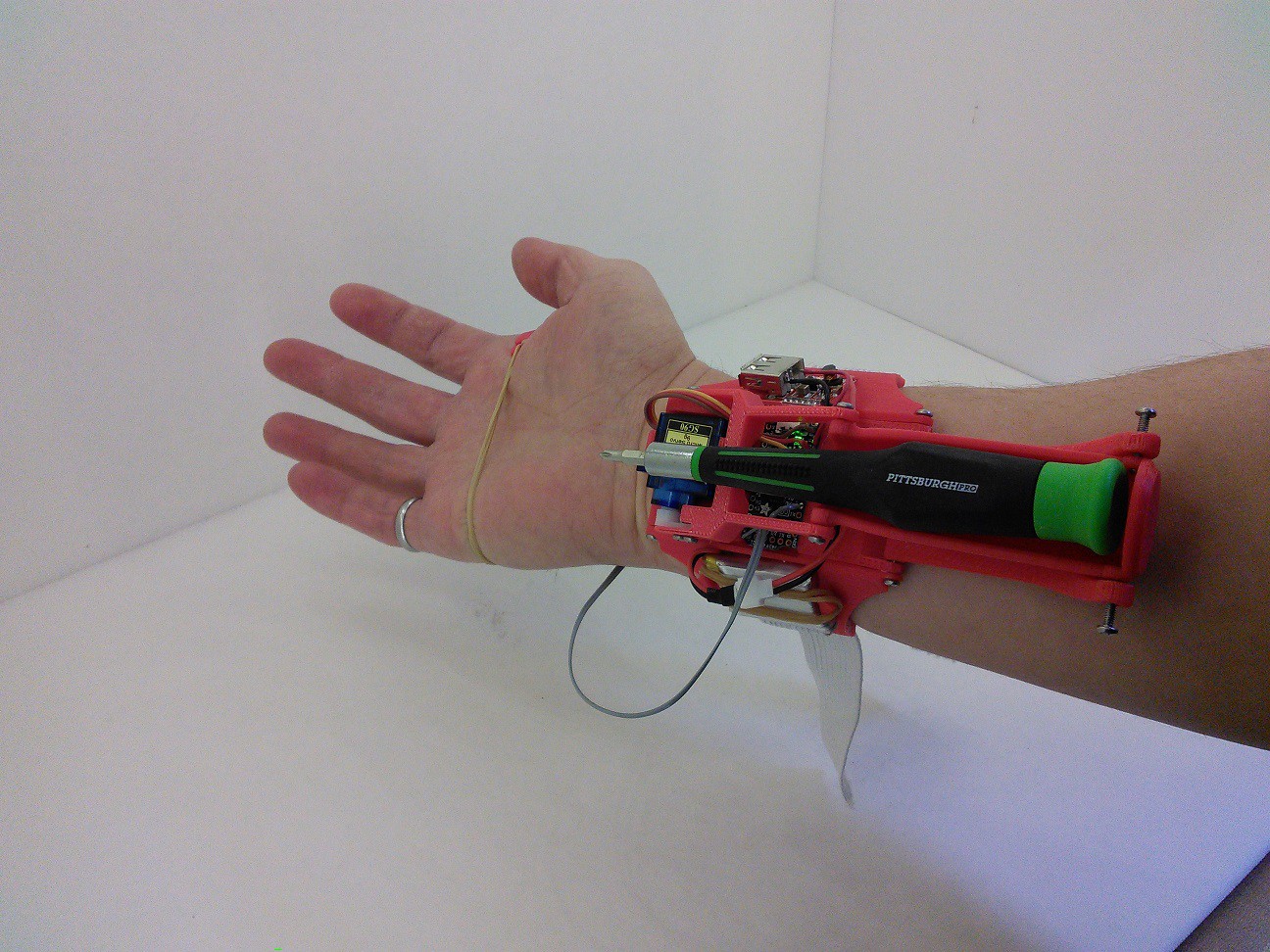
Here are a couple of videos of it all in action! This first video gives a good look at the whole Robotic Third Hand and it's motion.
This second video shows a real world use case for it's functionality as I secure the lower server into a MeArm. Notice that the movement and use of my right hand is not encumbered at all by the use of the Robotic Third Hand.
All the design file are up on thingiverse now: http://www.thingiverse.com/thing:618811.
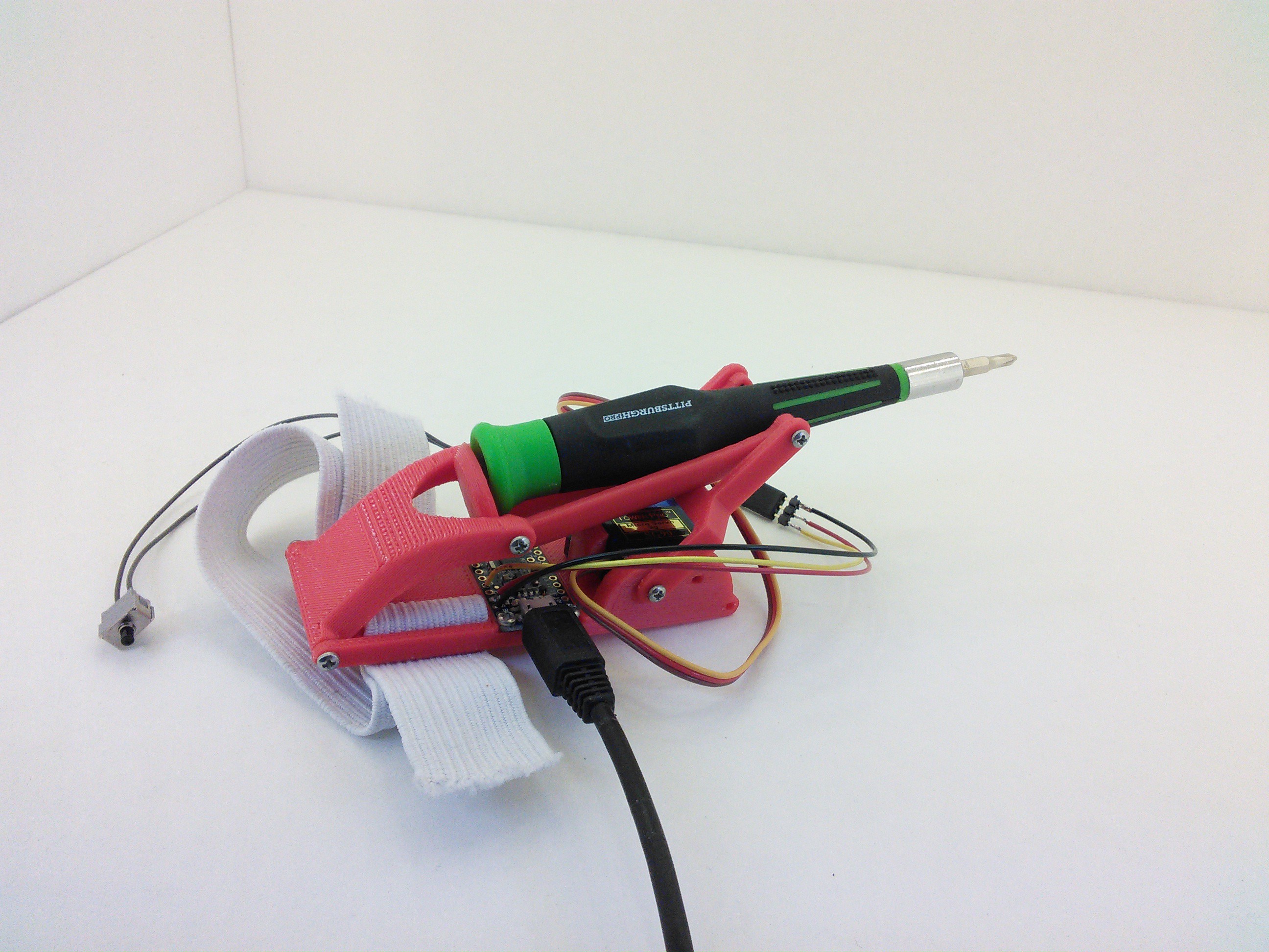
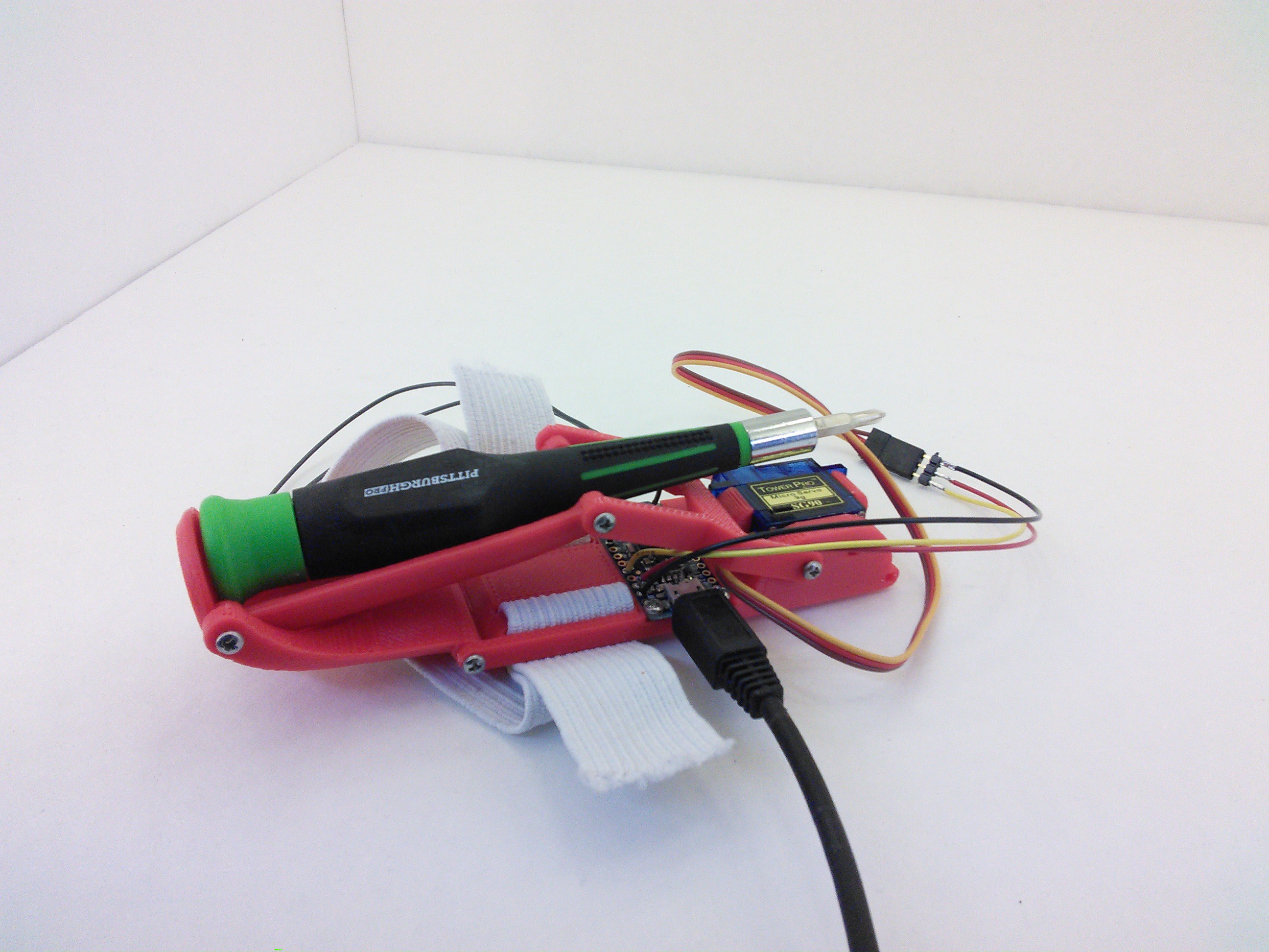
A few more pictures:
![]()
![]()
![]()
![]()
I guess that's all! Happy Hacking!
EDIT:
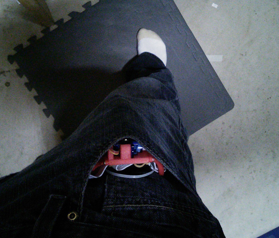
I wouldn't want to get disqualified based on the technicality of pocketability of my project. I interpreted the everyday carry-ness of my project as something that you would be able to wear on your arm everyday, the contest post spelling out the rules sounds like it needs to be carried in a pocket so....
![]()
It all fits! I still had more pocket too, I didn't push it down all the way so that you could tell that I actually had the Robotic Third Hand in there.
-
Refinement and Finishing Touches
12/30/2014 at 16:56 • 0 comments![]()
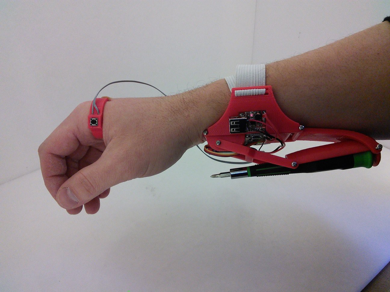
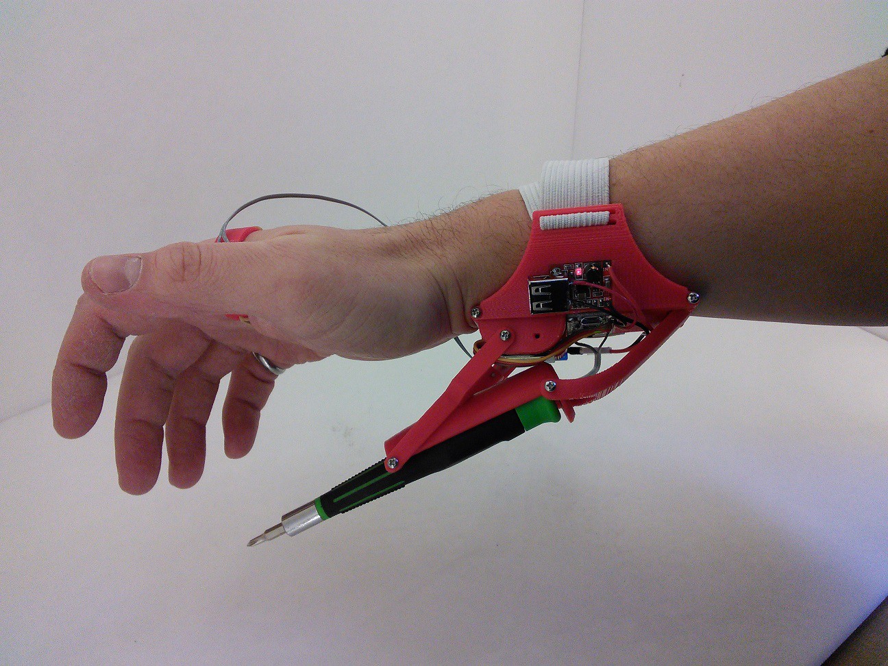
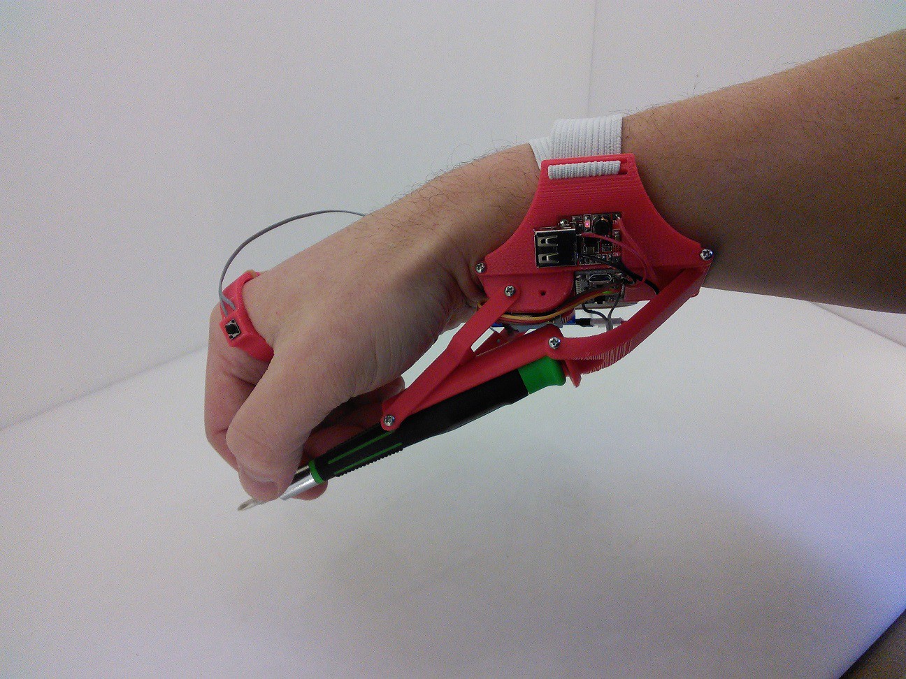
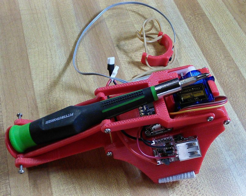
I went through 2 more revisions of the mechanical bits this week, taking me up to revision 5. I increased the movement of the screw driver by 1.5 inches, so it is much easier to grab. I also added 2 "wings" that follow the curvature of my forearm so that it fits ergonomically. One of the wings has a recess that holds the battery, the other wing has a recess that holds the 5V boost supply.
![]()
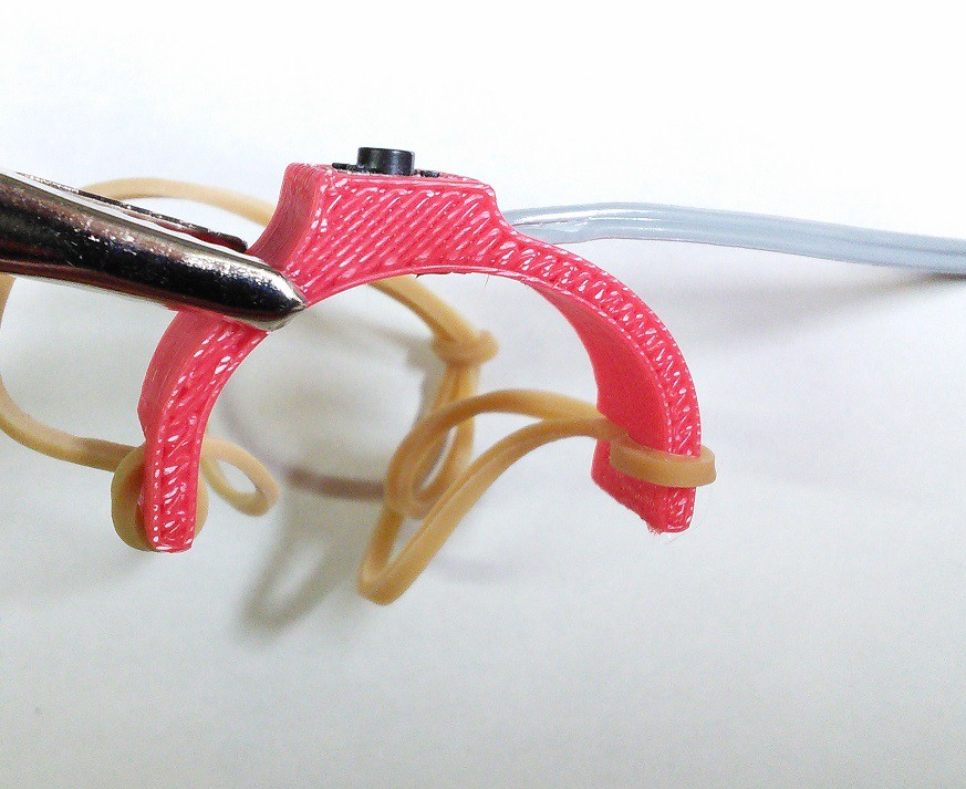
I used a common snap action SMT button that I removed from a garbage VCR for my official button and made a printed holder that is held on my hand with a rubber band.
![]()
I am very happy with how this all works. I'd like to add the flashlight functionality and an area to hold several of the screwdriver bits, but I'm not sure that I will have time to do that before the end of the contest. In the event that I don't get that done, I will continue development beyond the end of the EDC contest as I tweak this to my liking. :)
In the next few days I need to post up all my design files and put together some build instructions to make sure that I meet all the requirements of the contest.
-
Mechanical Motion!
12/23/2014 at 03:00 • 0 commentsSince the last update I was focused on getting the mechanical motion really nailed down. I went through 3 revision of the mechanical bits.
I didn't take any pictures of revision 1. That was more or less just a test to see if the geometries I was working on would even print.
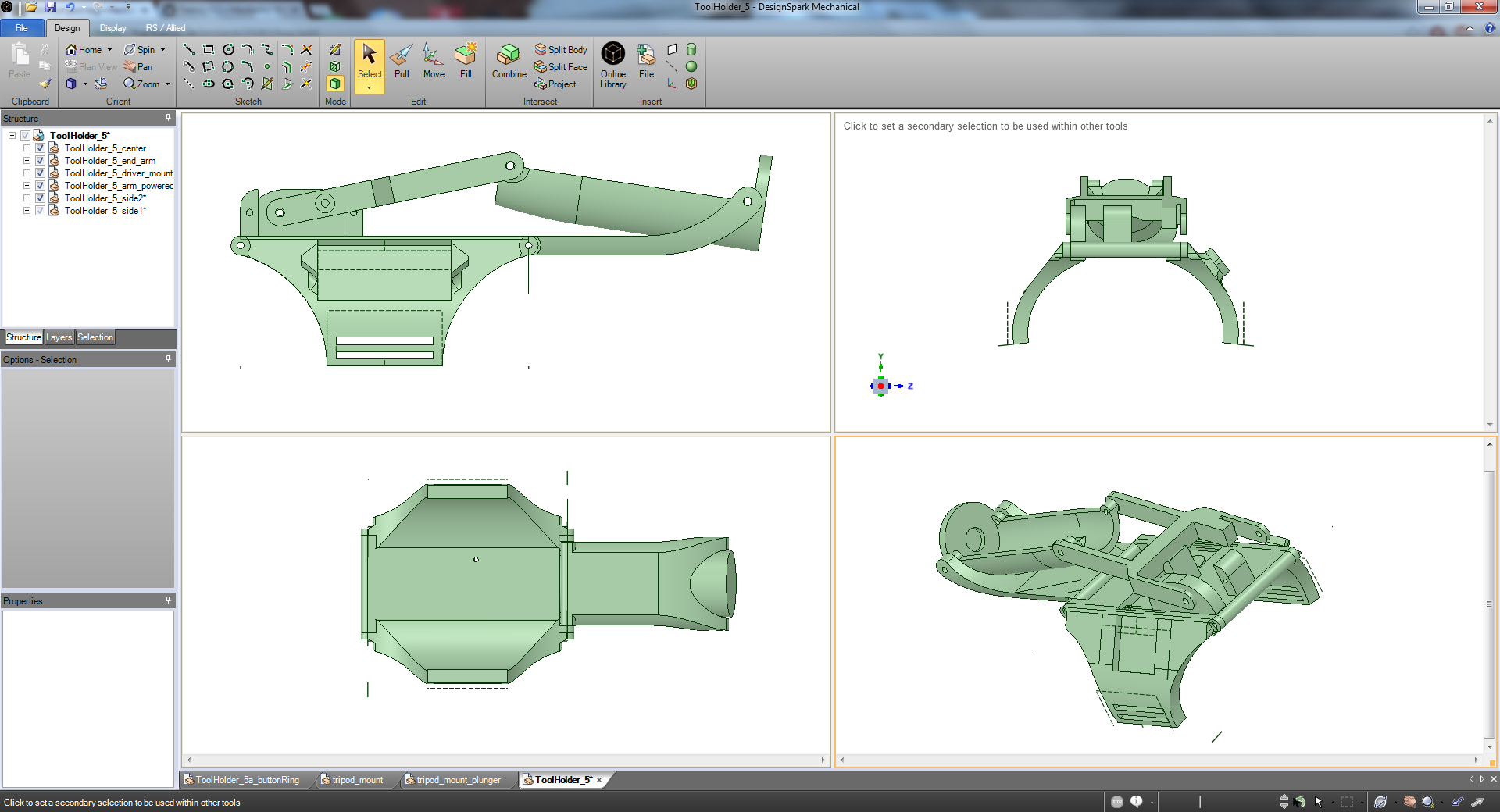
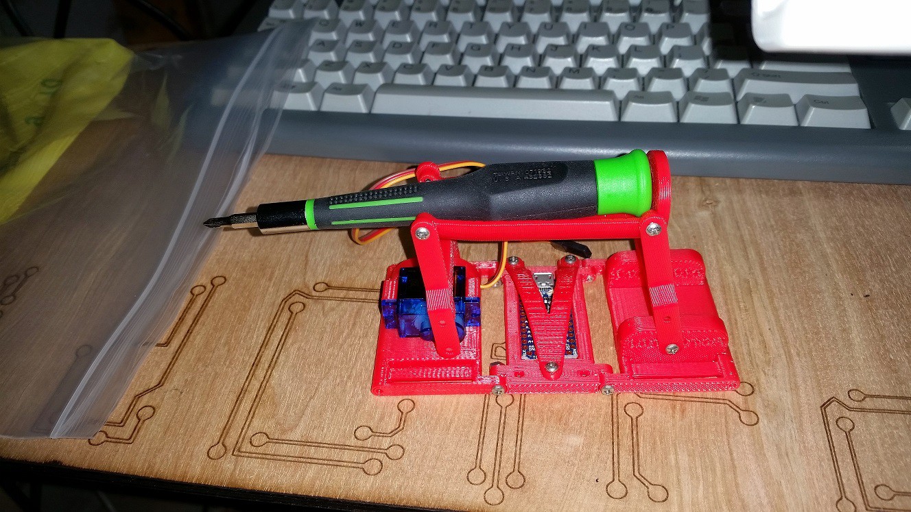
Revision 2 is pictured below. It is 3 sections screwed together. My printer is an UP! Mini (which I think is a fantastic printer) but it only has a roughly 4" print bed, and this contraption was a little more than 5" long. Having it be 3 separate sections also made the design a little easier. I'm doing all the 3D modeling in Design Spark Mechanical and I'm learning a lot along the way. Before this project I only ever used design spark to make really simple parts, but this project is forcing me to learn how to use it well. This revision didn't work out awesome. I wanted the screw driver to get slanted up when fully extended, but I didn't get my hinge points correct with this model to make that happen. I also had a few interferences with the arms when trying to move over the full range.
![]()
Revision 3 of the hardware is a big improvement over revision 2. Trying to fix some of the interferences of revision 2 lead me to realize that the right most section of the design really wasn't necessary. I could instead make the whole third section an arm. And it needed to be contoured to the screwdriver holder to make it fold up nicely. With the 3rd section gone I could now print sections 1 and 2 as one piece, so I merged them together and moved the Trinket Pro a lot closer to the servo.
![]()
![]()
Revision 4 is going to be necessary to fix a few more issues. The screwdriver needs to extended about an inch further to your hand to make it easy to grab. Also I need to integrate a small battery area. I don't think I'm going to use my 18650s, I got a cheap 5V boost supply that can run off of a single lithium cell. I'm going to see if some of my small indoor quad batteries will drive it OK.
I threw together a real quick servo moving sketch for the Trinket Pro and put on a button so I could see it in motion and test fit it on my arm.
Lastly - I've decided to scrap the EMG circuit. Even with everything all tuned up well, it is unreliable. I probably just need to buy a nice set of skin probes, but my home made probes are difficult to get good skin conductivity. And I don't want to muck around with probes that wear out and require a conductive gel to be used. That would just be a barrier to this thing actually being useful. I haven't decided yet how I will actuate it, but the EMG is out the door. Now I need to think up something creative that the EMG in my project name should stand for. Suggestions? I'm thinking Electro-Mechanical... Glove? Gauntlet?
-
EMG is working + Test Carrier
12/16/2014 at 01:45 • 0 comments![]()
Since my last update I populated my EMG sensor board and made a few changes to the design. I had put down a MAX1720 switched capacitor voltage inverter to create the negative voltage, but found that it's switching noise was corrupting the output of the first amplifier. The MAX1720 has an ~11kHz switching frequency, making it very difficult to filter out. If I was using something based on an inductor with a ~1MHz switching frequency it would be very easy to filter out. I used series 35 Ohm resistors followed by 47uF caps for both the V+ and V- supplies to filter them. This seems to have been enough to fix that issue. However, while testing the next day I forgot that the absolute maximum Vin of the MAX1720 was 6V. I tried the EMG board with 6V while troubleshooting what was actually a probe/skin interface issue, as I remembered that all the OPAMPs should be perfectly fine at 6V. Sadly, that blew up the MAX1720. So for the time being I've wired around the MAX1720 using 2 18650 battery cells to test. Once I have everything working I'll replace the MAX1720. I bought 2 of everything when I ordered my EMG parts last week. :0) I figured that something like this might happen. With the batteries I have confirmed that the EMG circuit is up and running.
![]()
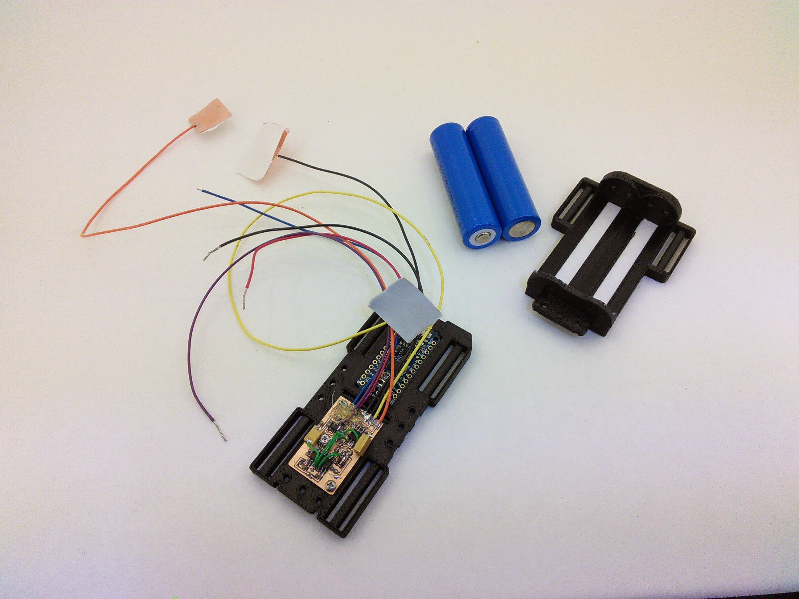
I 3D printed up a test carrier housing for the EMG board, trinket board and batteries. I find time and time again that it is best to have boards in some sort of case / development fixture when I'm working on things like this. With the wires all over the place traces get ripped off of boards, or random screws on my workbench will short out the connections on the board. I integrated a belt loop feature on the side of the test carrier so that I could strap the whole things to my arm for testing. I just determined that the loops need to be improved because the elastic material that I got to use as straps doesn't stay put in them like I thought it would.
With the batteries in I didn't have any way to measure the current draw so I busted out my mega-sweet Seek Thermal Camera to see if it was getting hot. It was not, so all was good.
![]()
The next big step is working on the mechanicals of this contraption. Hopefully what I have floating around my head is actually creatable. :)
-
The Beginning
12/09/2014 at 03:16 • 0 commentsI have been dreaming up this project for a long time, and the Trinket Everyday Carry Contest is the perfect excuse to actually do it. I started about a week and a half ago to acquire parts and brainstorm how I'm going to create this thing.
Before I read about EMGs, I was planning on wrapping a flex sensor around my forearm and hoped that I would get enough feedback out of it that I could detect patterns of muscle movement. Some preliminary experiments make me think that would be either very difficult or unreliable.
I found the "Muscle Sensor V3" (http://www.advancertechnologies.com/p/muscle-sensor-v3.html) and thought that would be perfect for what I want to be able to detect... but $50? I probably would have paid $20, but $50 was out of the budget for this project. The guys at Advancer Technologies were nice enough to post all their schematics though, so I took that design and improved it with a MAX1720 switch capacitor voltage inverter so that the EMG circuit can run on a single cell. (The opamps need a +, GND, and - voltage rail). All my parts arrived for the EMG circuit from Digikey today (12/8/14), my Trinket Pro arrived sometime last week. Friday at lunch I took advantage of my at work access to a T-Tech pcb mill over lunch and cut out the board that I drew up for the EMG circuit.
![]()
![]()
Robotic 3rd Hand
The Robotic 3rd Hand is worn on the forearm and hands you a tool right when you need it.