David Hopkins
-
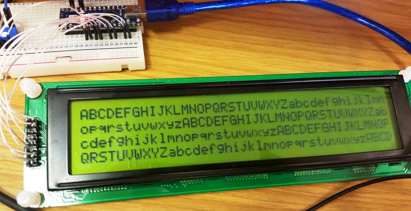
PC4004 LCD working :-)
03/03/2015 at 15:08 • 0 commentsfinally got the friggin thing working, and fast too, using the LiquidCrystalFast Library :-)
![]()
-
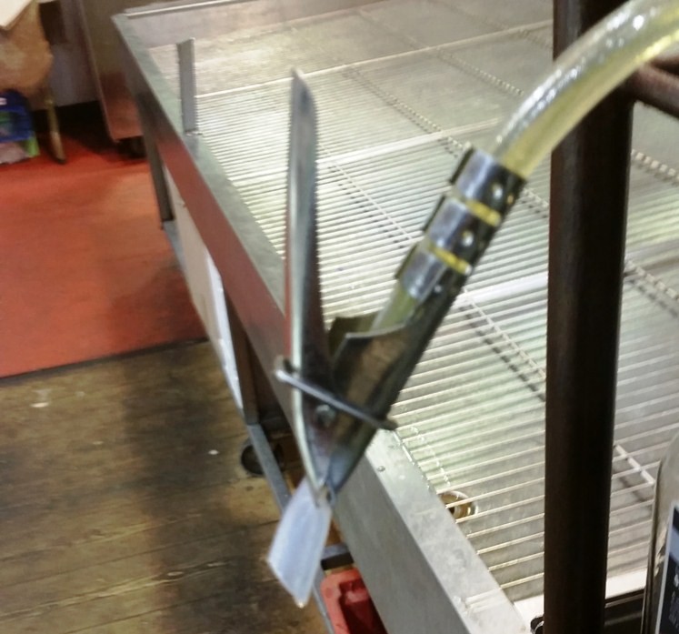
Alternative clamp-valve design
03/02/2015 at 09:03 • 0 commentswhilst i was away visiting family, saw this on a bottle of olive oil - v nifty, could be useful in future iterations, though it would take up more space.
![]()
-
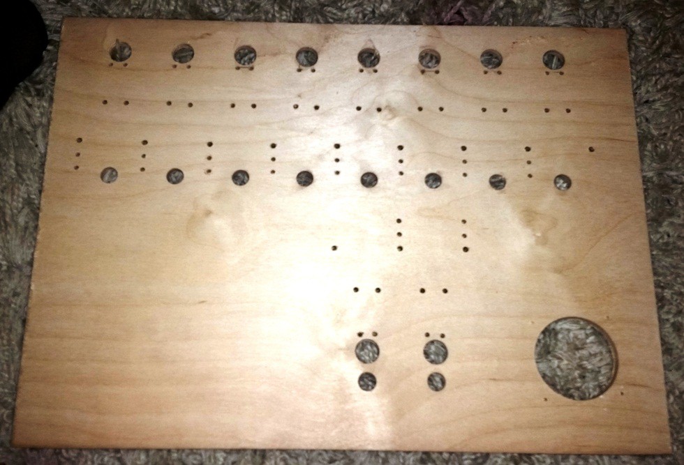
Template Drilled
03/02/2015 at 09:01 • 0 commentsWith help from a friend (John Ward BA MCMI) and his workshop, the template is now drilled :-) missed a coule of holes off the template but that was easily sorted.
the result:
![]()
Now for finishing and varnishing to protect it from spills etc, then i can stat building the thing :-)
-
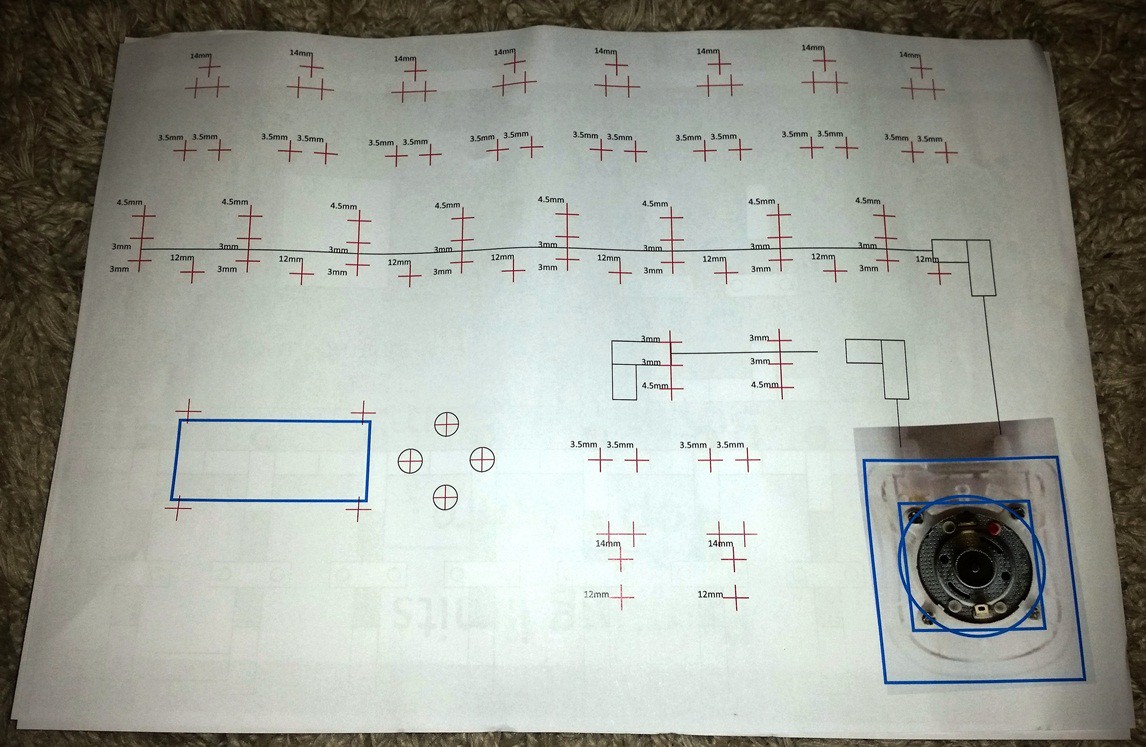
Drill Template
03/02/2015 at 08:58 • 1 commentDrill template created:
![]()
preliminary markings for the buttons and the display, probably wont be cut out until i know what display I'm using; i have recently got a 4004 (40 char, 4 line) display that I'm going to try to get working with the i2c backpack. The size of the display will determine the position of the buttons.
-
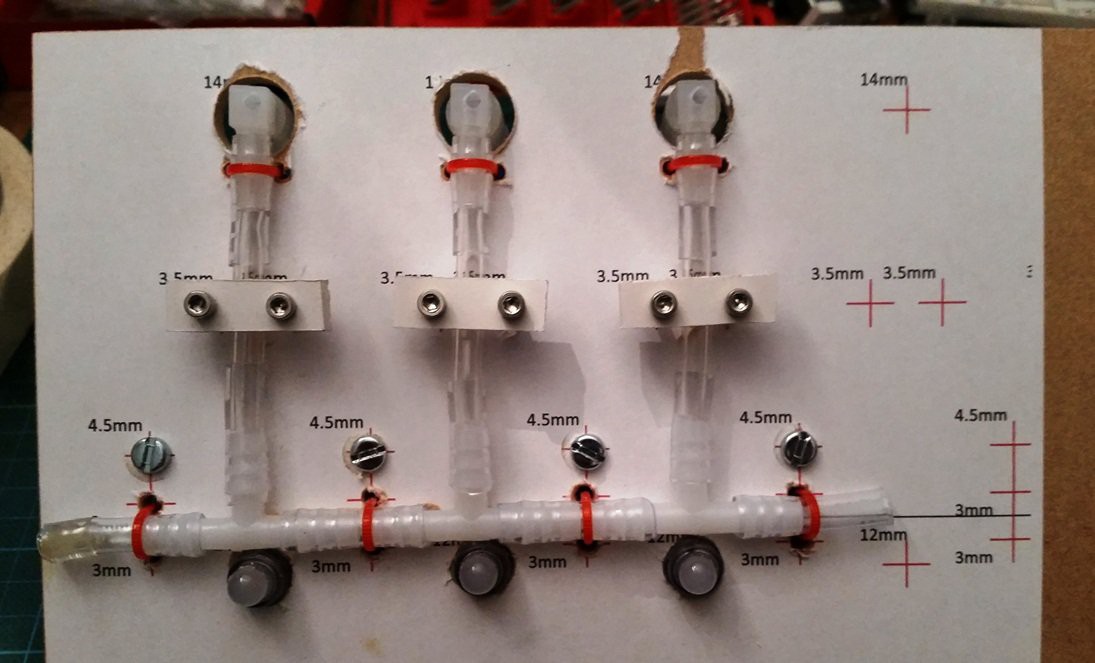
Testing the drill template and pipework layout
02/16/2015 at 10:47 • 0 comments![]()
will need some fine tuning but the spacing works out well, toying with the idea of using different leds underneath the T joints to illuminate the plastic connectors, but not sure. may just have a L connector on the end instead of capping it off, will def be neater.
-
Clamp/Valve Design
02/04/2015 at 16:17 • 0 commentsBased on some numbers I ran through a handy tool, if I have a short (40mm) length of 4mm tube in the run of 6mm, based on the flow rate of 500ml/min the pressure difference will be negligible.
2meters of 6mm pipe at 500ml/min results in 0.52 mBar - Reynolds number 1768.39 (Laminar Flow)
40mm of 4mm pipe at 500ml/min results in 0.53 mBar - Reynolds number 2652.58 (Transition region Flow)
so if I have a short length of thinner, flexible pipe for the valve, I can keep the same, proven design and not have any major pressure/flow issues. From what I understand from the Reynolds number, the smaller pipe is on the verge of turbulent flow eg causing chaotic eddies, vortices and other flow instabilities. Whereas the rest of the pipe will exhibit laminar flow eg smooth and, well straightforward.
I'm not sure if the internal diameters of the connectors, but they may end up by having more of an effect than the 4mm pipe sections... we shall see.
-
Pump, sequences and LCD display
02/04/2015 at 08:56 • 0 commentsPump arrived, a doddle to hook up, seems to work well, will check the flow rates this evening. Its louder than I had hoped but hey ho.
LCD display found in parts box (and I2C backpack), basic feedback given. will form the core of the HUI (with buttons).
Sequences work well, using the serial interface, the sequence in the video is "R1010R2020R4030EC"
This translates to: Reagent 1 10ml, reagent 2 20ml, reagent 4 30ml, End sequence(flush with air), Clean sequence(divert to dump pipe, flush with water then air)
New pipe also arrived but its very thick, I may have to either redesign the clamp mechanism, use thinner pipe, or just use thin sections for the valves. Unsure what route to take until I can test further.
-
Pipe routing decision made
02/02/2015 at 10:56 • 0 commentsits going to be a through-board solution, it will be a little more tricky to make as will need to design all the holes before drilling, and slightly more fiddly to assemble, but it will look a lot nicer, a neater look. Also allows for some kind of edging on the baseboard
![]()
-
codebase established
02/01/2015 at 18:08 • 0 commentsFading LEDs and decent servo control implemented, now to make wrapper functions etc for dispensing sequences
-
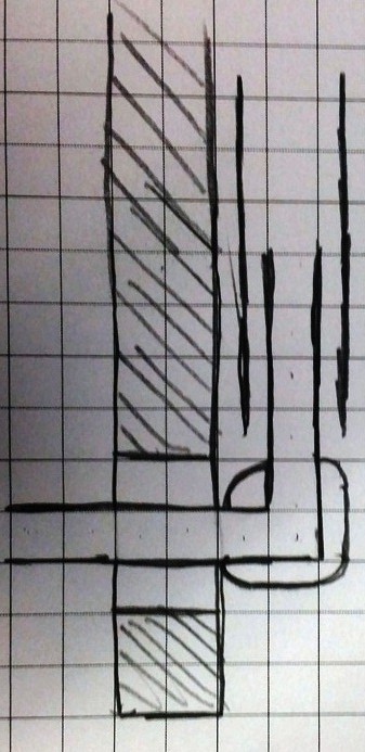
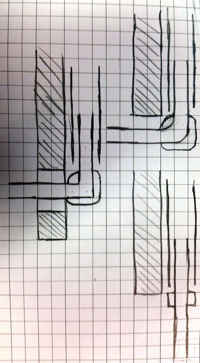
Design Decision: pipework exits/entrances
01/30/2015 at 15:48 • 0 commentsI need to decide how im going to connect the pipework to the board, various options as detailed below are: elbow over the edge, straight connector for dangling tube and elbow through the baseboard.
straight connector would be easiest i think, and elbow-through-board would be the neatest by far.
not sure how to decide, hmmm
![]()