 Bruce Land
Simulated visual system
We want to use artificial neural systems to teach biological
instrumentation methods. The goal is a set of small circuits which
behave like neural systems with respect to voltage, timing, and system
behavior. This will enable students to exercise their skills in setting
up amplifiers and oscilloscopes, getting rid of noise, connecting to a
computer and writing software , while concentrating on the electronic
technology, rather than the biological technology. We believe that
modeling is no substitute for work with real animals, but modeling can
help in understanding electronic and logical concepts before the
students use real animals.
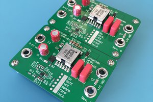
We built a simple model of an array of light sensors with the following properties:
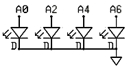
- The light sensitive elements are LEDs being used in a
photovoltaic mode. The voltages produced by the LEDs are digitized by
the microcontroller. Each positive lead of each LED is connected to a
ADC channel (0,2,4,6). The negative leads are all grounded. The
schematic is shown below.
![]()
- Sensor output is proportional to light intensity, but has a highpass characteristic which simulates accomodation to a fixed light level. The highpass filter is simulated on the microcontroller.
- The sensor outputs go to integrate-and-fire (IF) neurons which are simulated on the Atmel mega32 microcontroller.
- There are four sensors and four IF neurons. Each sensor excites its respective neuron, and inhibits the neurons on each side This simulates lateral inhibition. The equations for this are given below.
- Each neuron has a different amplitude and duration action potential output so that the neurons can be distinguished. The outputs may be made the same to make analysis more challanging.
- All four digital spike trains are summed together in the microcontroller, as if the student were recording from a nerve containing all four axons.
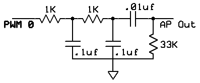
- The digital spike train is modifed by an analog highpass/lowpass
filter to more closely resemble real extracellular recordings. The pulse
train output from the microcontroller was shaped using the following
circuit. The two lowpass sections surpress the 62,500 Hz PWM artifact
and limit the rise rate. The highpass section produces the undershoot at
the end of the AP. The final version will probably have a voltage
divider added to the output to make the amplitude a few millivolts.
![]()
The Codevision C program running on the Mega32 microcontroller consists of three parts:
- Initialization
sets up
- PORTA for analog input and sets up the A/D converter for lef-justifed read using the internal Vcc reference.
- PORTB for pulse width modulator (PWM) channel 0 output. This allows D/A output.
- Timer0 to run the PWM at 62,500 samples/sec. The fast PWM cycle helps with filtering out PWM noise.
- Timer1 to interrupt every 2048 cycles (about 7800 Hz) to update the neuron dynamics and the PWM value.
- UART for debugging
- Turns on interrupts
- The timer interrupt
- Updates the integrate-and-fire neuron voltage.
For speed, all operations were done in 16-bit integer arithmetic, using only add, subtract and shift operations. Multiplies are too slow. The equations were scaled by multiplying by 64 to avoid fractions. For the 4 cells the voltages updates were
v[0] = v[0] - (v[0]>>6) + (neuronInput[0]<<gain1) - (neuronInput[1]<<gain1) ;

      v[1] = v[1] - (v[1]>>6) + (neuronInput[1]<<gain1) -
(neuronInput[0]<<gain2) - (neuronInput[2]<<gain2) ;

      v[2] = v[2] - (v[2]>>6) + (neuronInput[2]<<gain1) -
(neuronInput[1]<<gain2) - (neuronInput[3]<<gain2) ;

      v[3] = v[3] - (v[3]>>6) + (neuronInput[3]<<gain1) - (neuronInput[2]<<gain1) ;
and the inputs are scaled up to account for the factor of 64. Nearest neighbor inputs were subtracted so that uniform illumination produced no output. The>>6corresponds to a membrane time constant of a few mSec. The indices refer to cell number. - Detects threshold crossing and forms action potentials and refractory periods by counting the number of clock ticks...
- Updates the integrate-and-fire neuron voltage.


 BleakyTex
 James Wilson
yes its very amazing to see this article i read it through out and there is no point where i disagree with you realy refreshing article i am also working on the similar project you can see here https://myhorsenames.com/