Mike Rigsby
-
Testing the Large Servo Motor
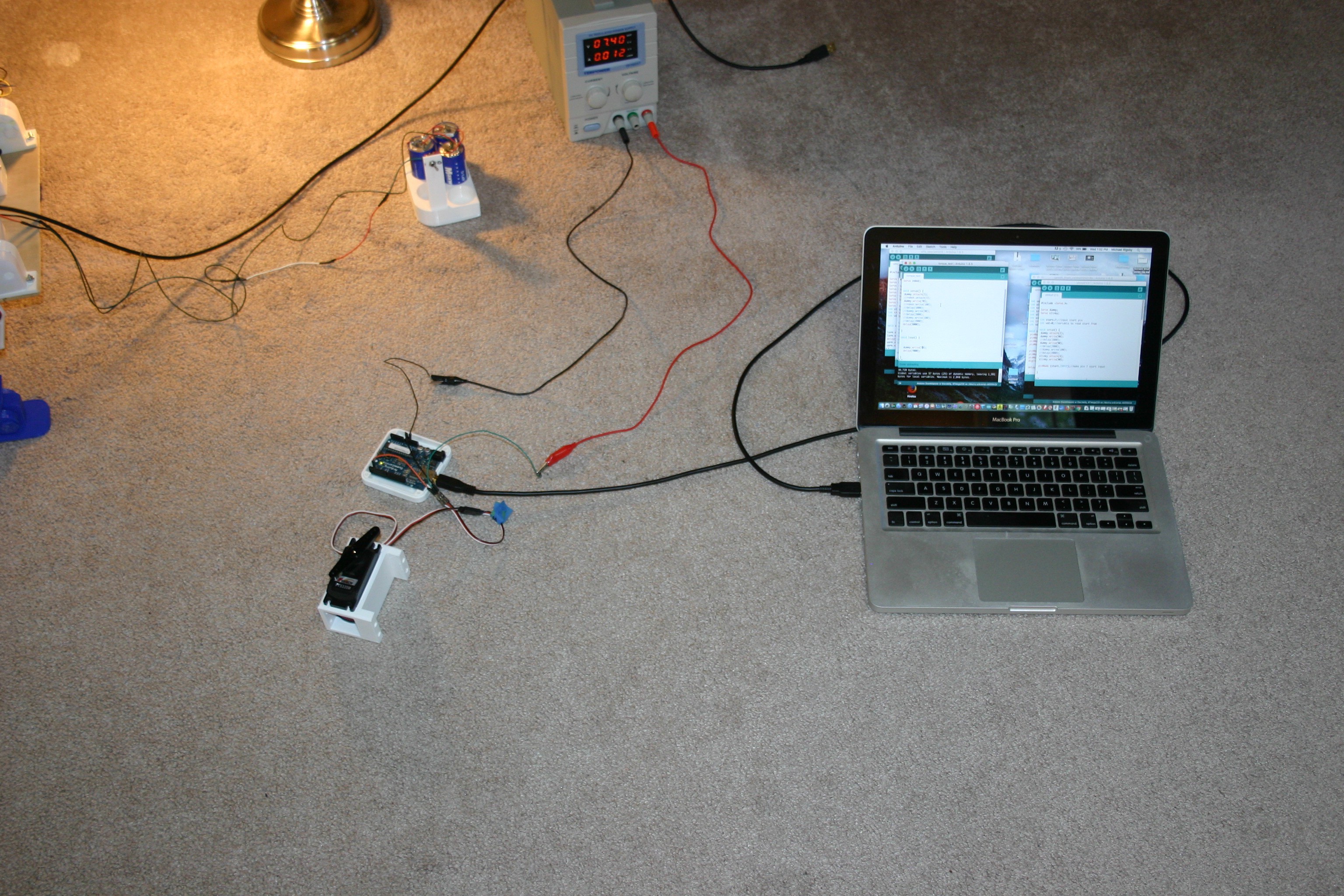
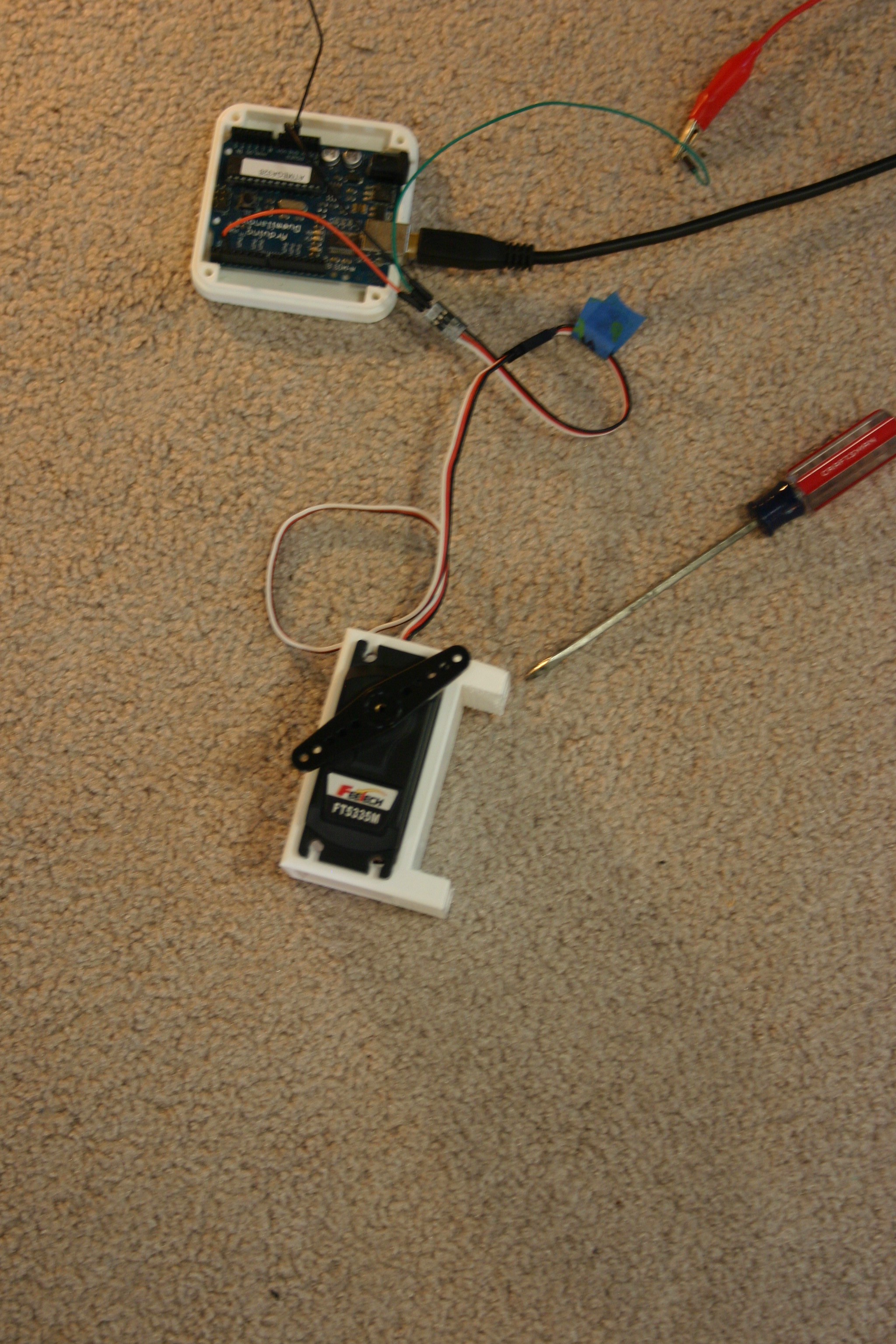
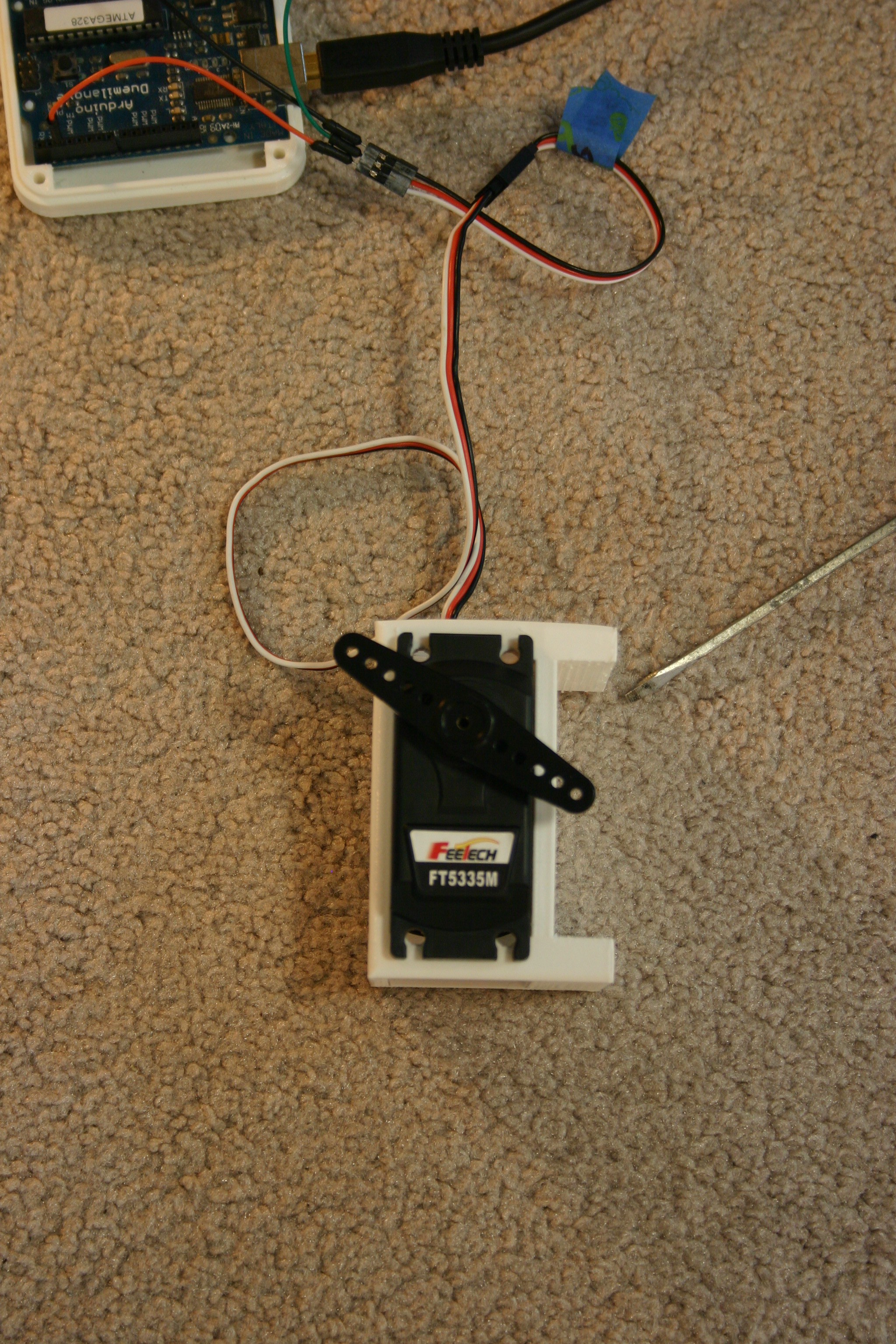
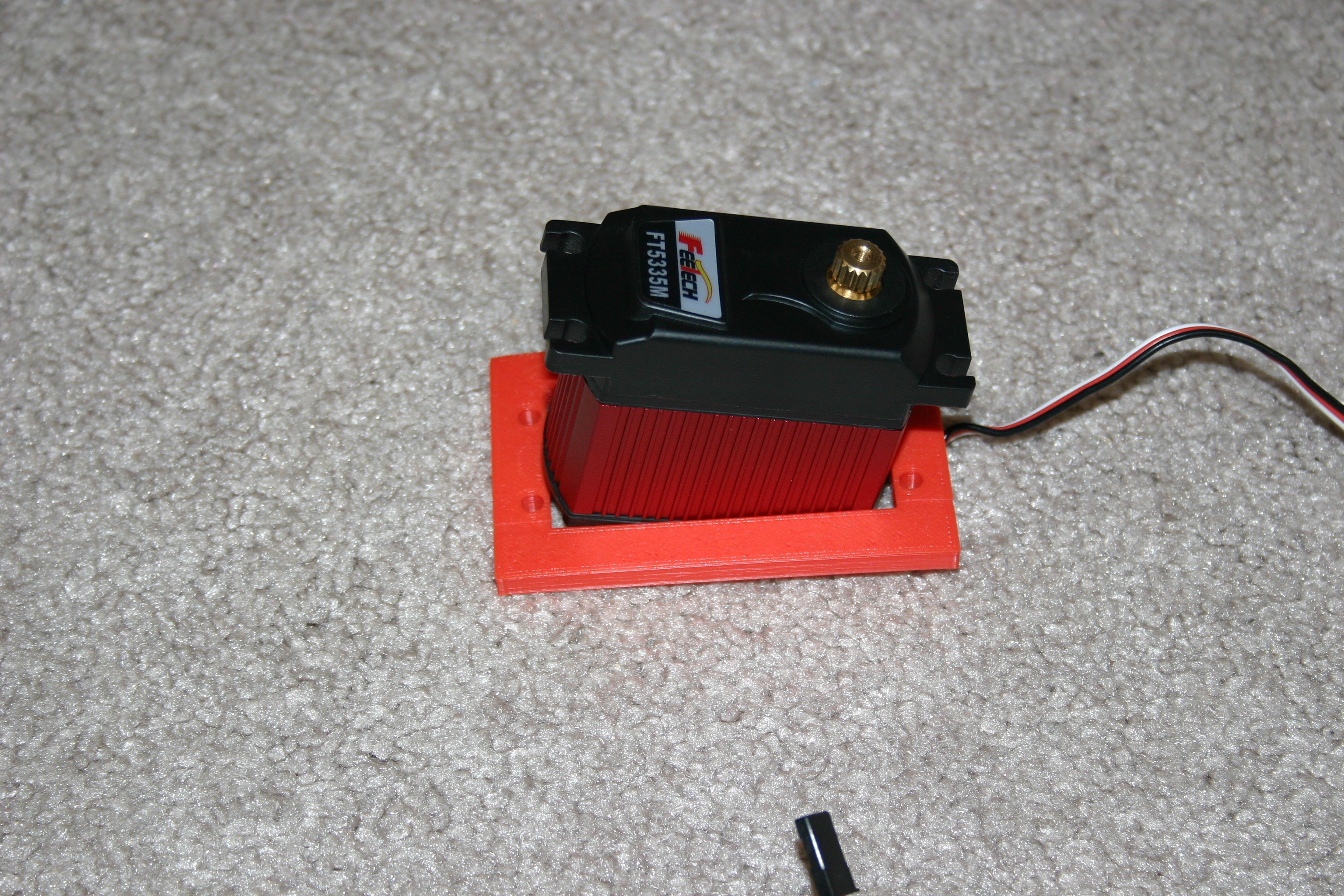
04/11/2018 at 19:12 • 0 commentsBefore changing the servo motors, I need to know something about the motion limits and power requirements of the large motors (FT 5335 M from Pololu).
![]()
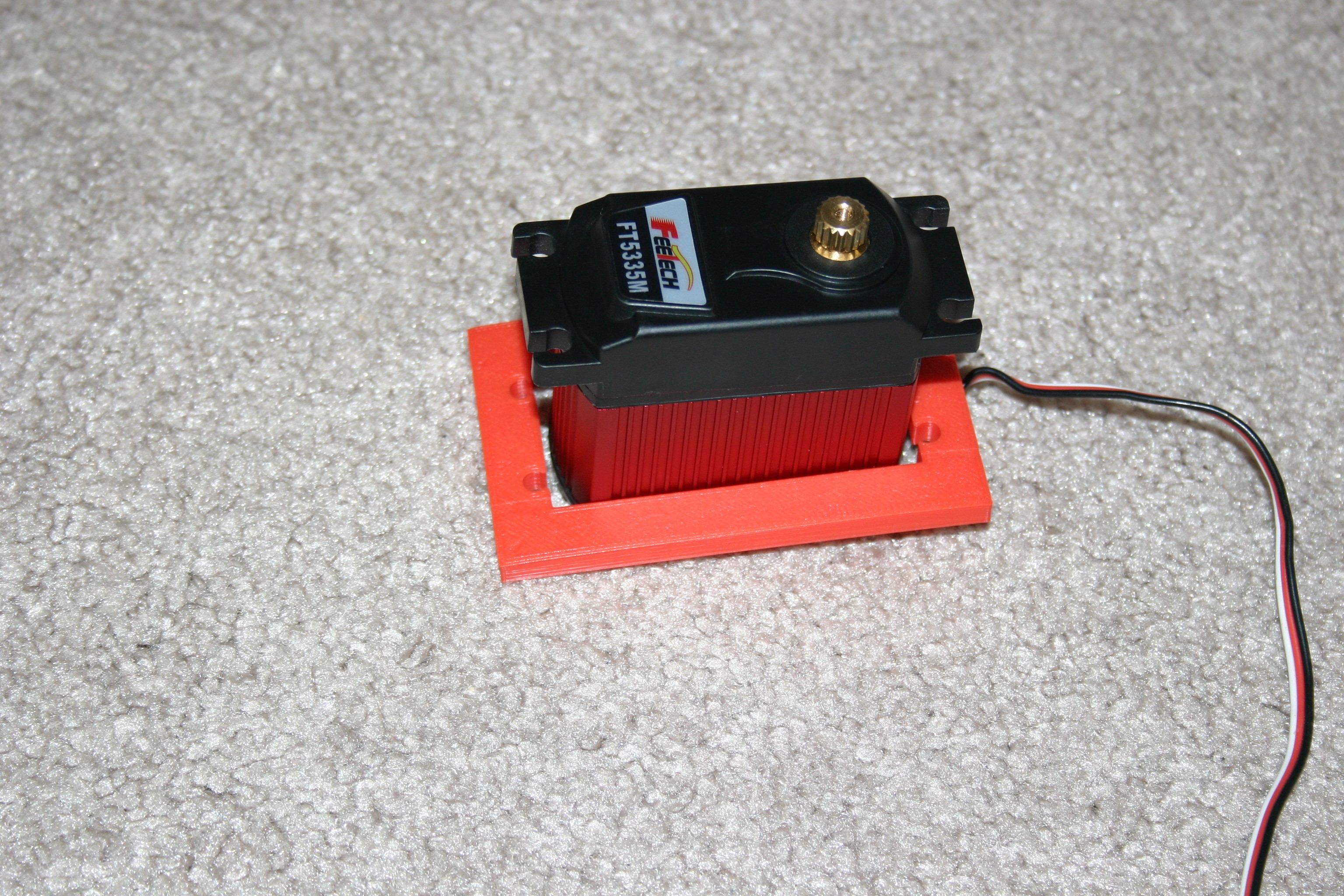
Using an Arduino, any commands lower than 30 degrees do not correspond to movement, thus 30 degrees represents the most clockwise position (viewed from the top).
![]()
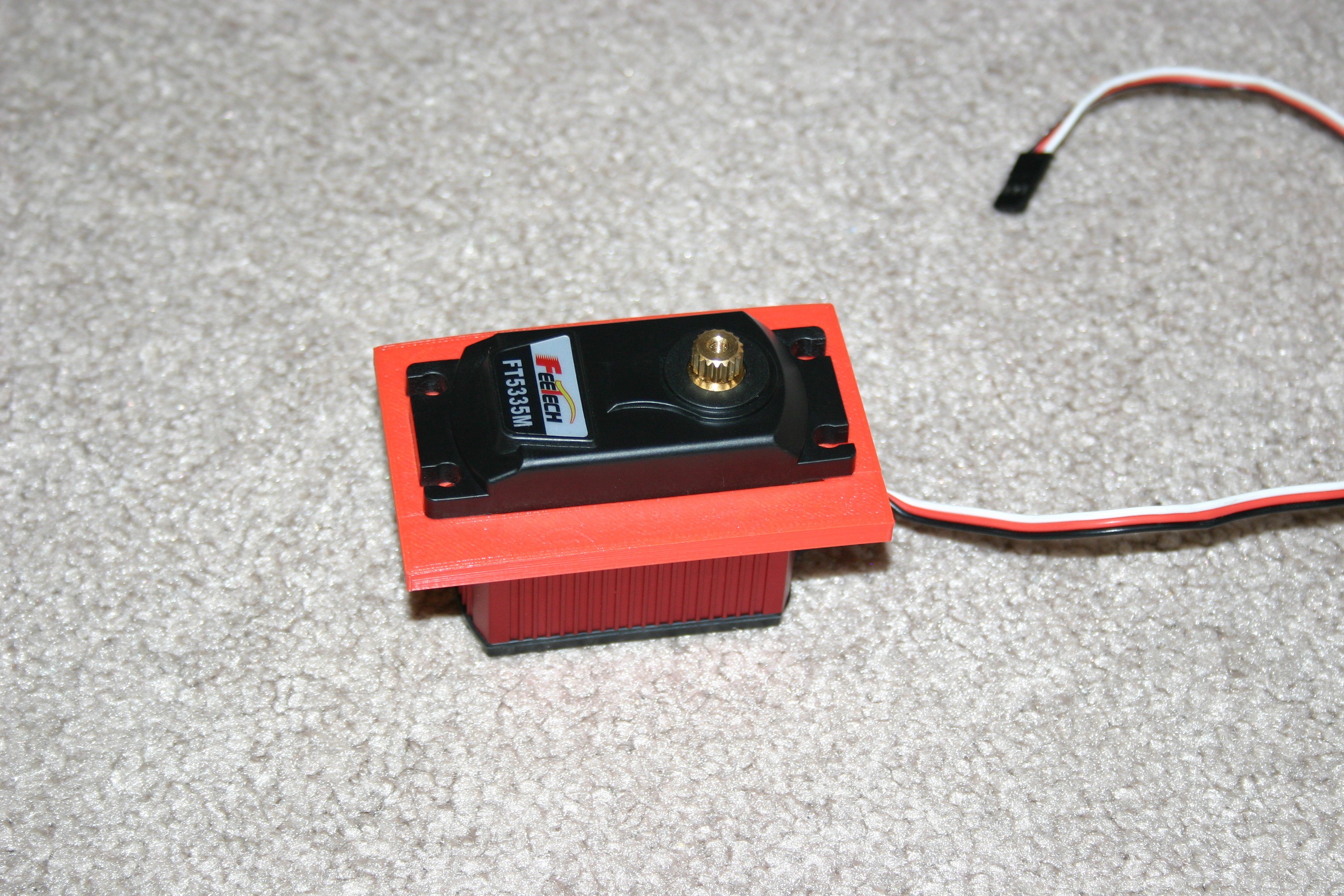
The 150 degree command is the last one that works in the counter clockwise position, thus I have about 120 degrees available for movement.
![]()
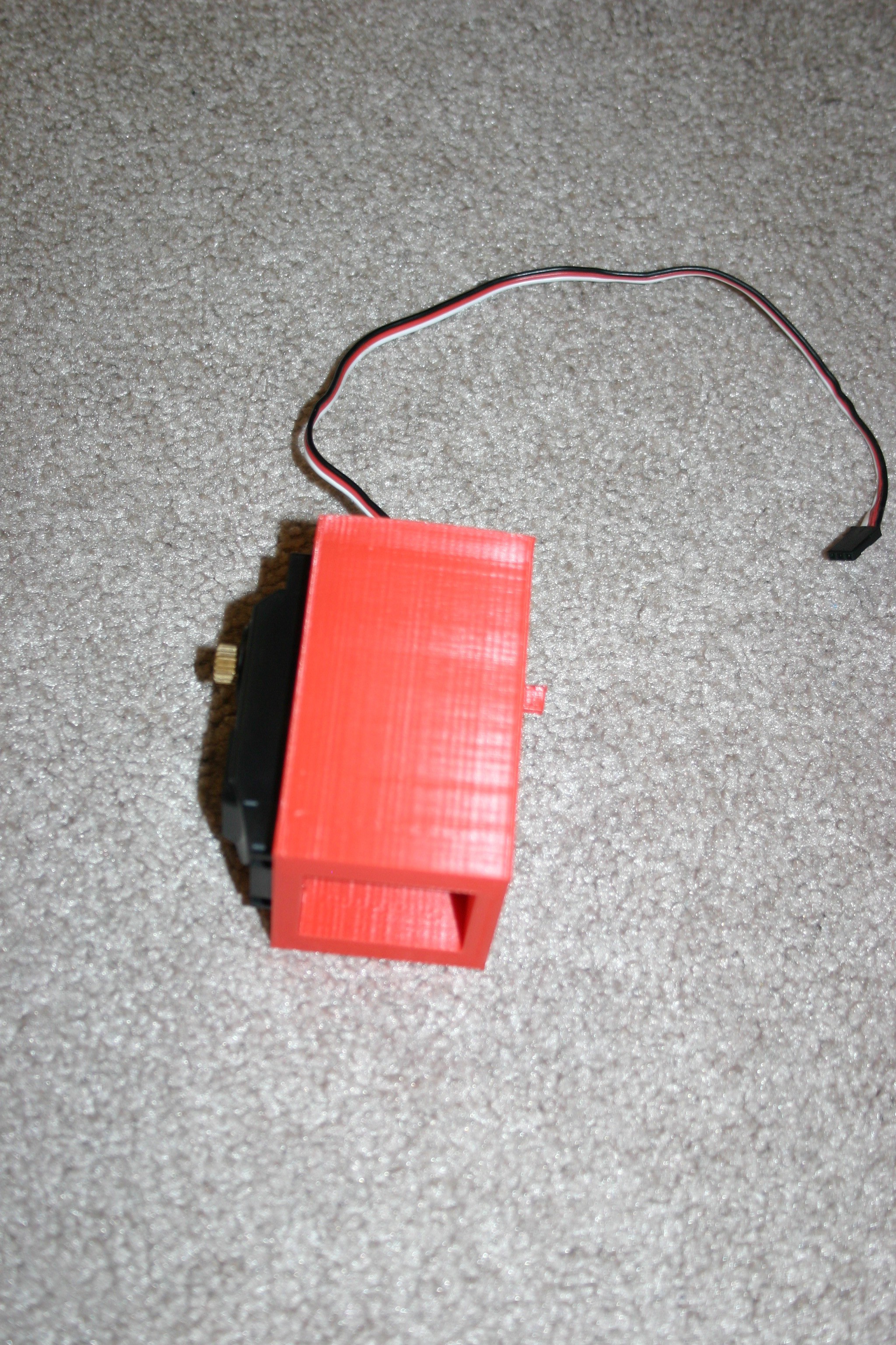
At 7.4 volts, two amps minimum is needed to during unloaded motor travel. About .12 amps are required to stay in position with no force applied.
-
Larger Servo Motor
03/30/2018 at 19:22 • 2 commentsThe dog stands, but just barely. As long as the voltage remains solid, motors don't overheat and all four legs share the lift in a fairly even manner, she will stand.
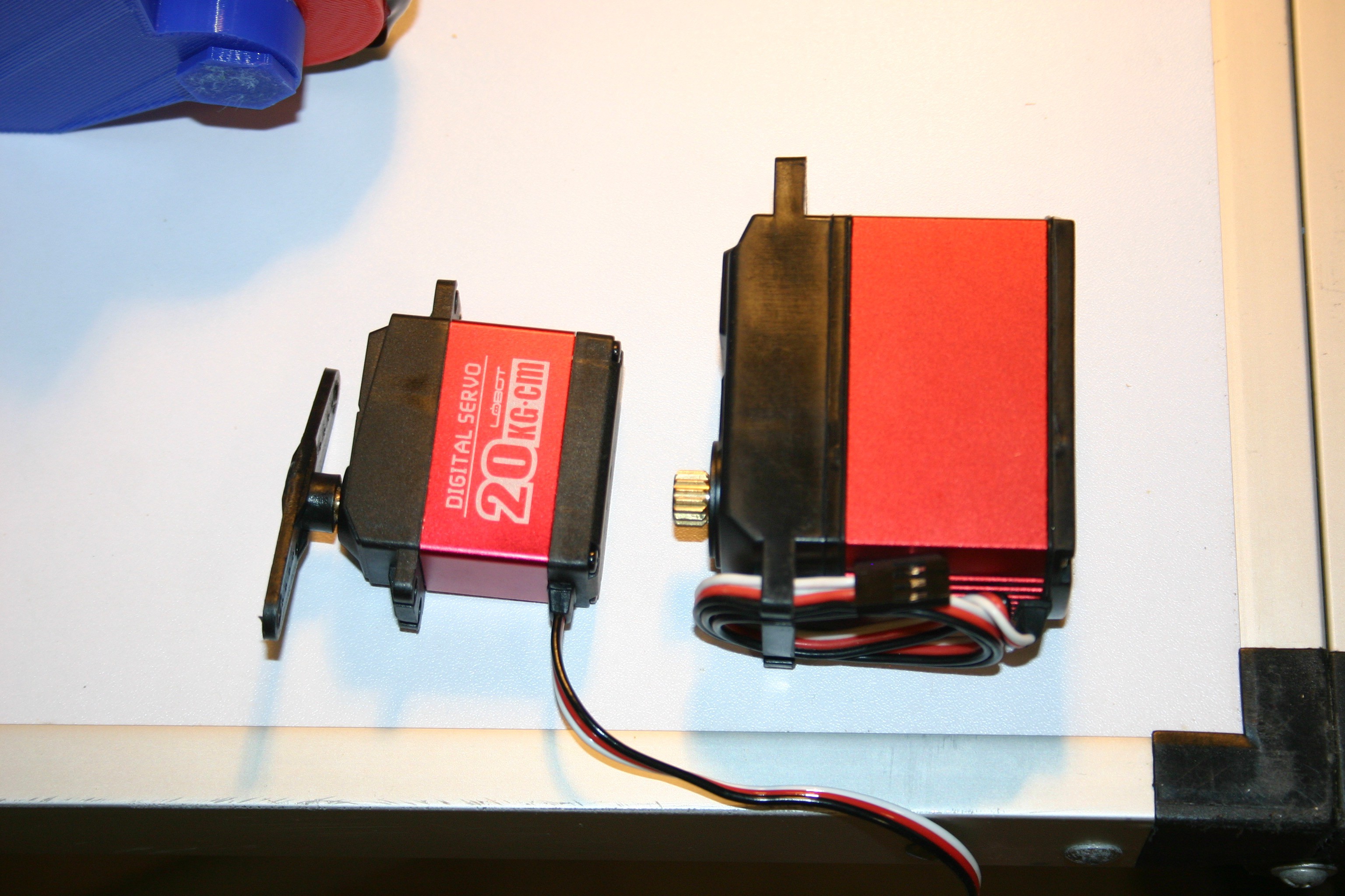
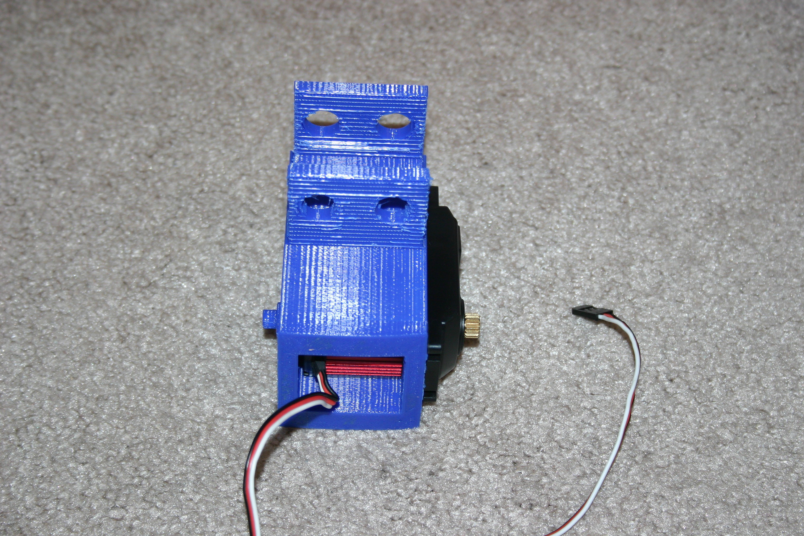
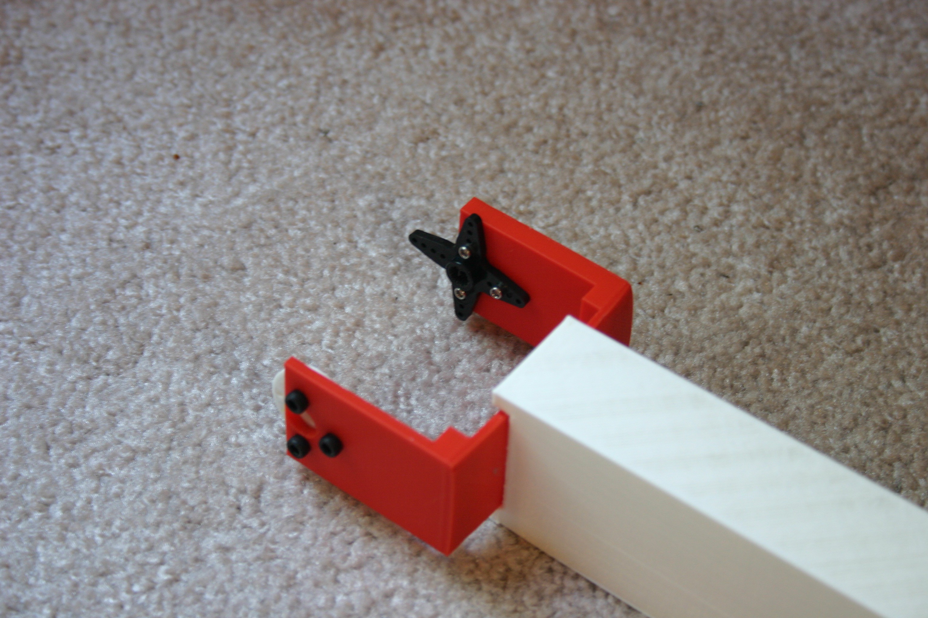
It's time for more torque. I'm trying a larger servo motor (1/4 scale) that provides double the torque of my current motors (550 oz. in versus 277) at slightly more than double the cost ($39.95 each).
Here's what the new motor looks like compared to the old one.
![]()
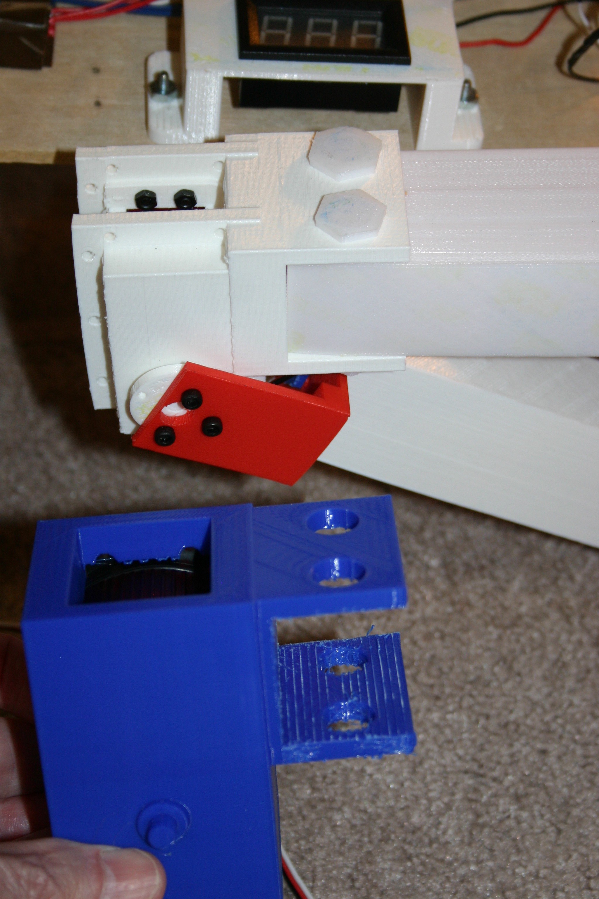
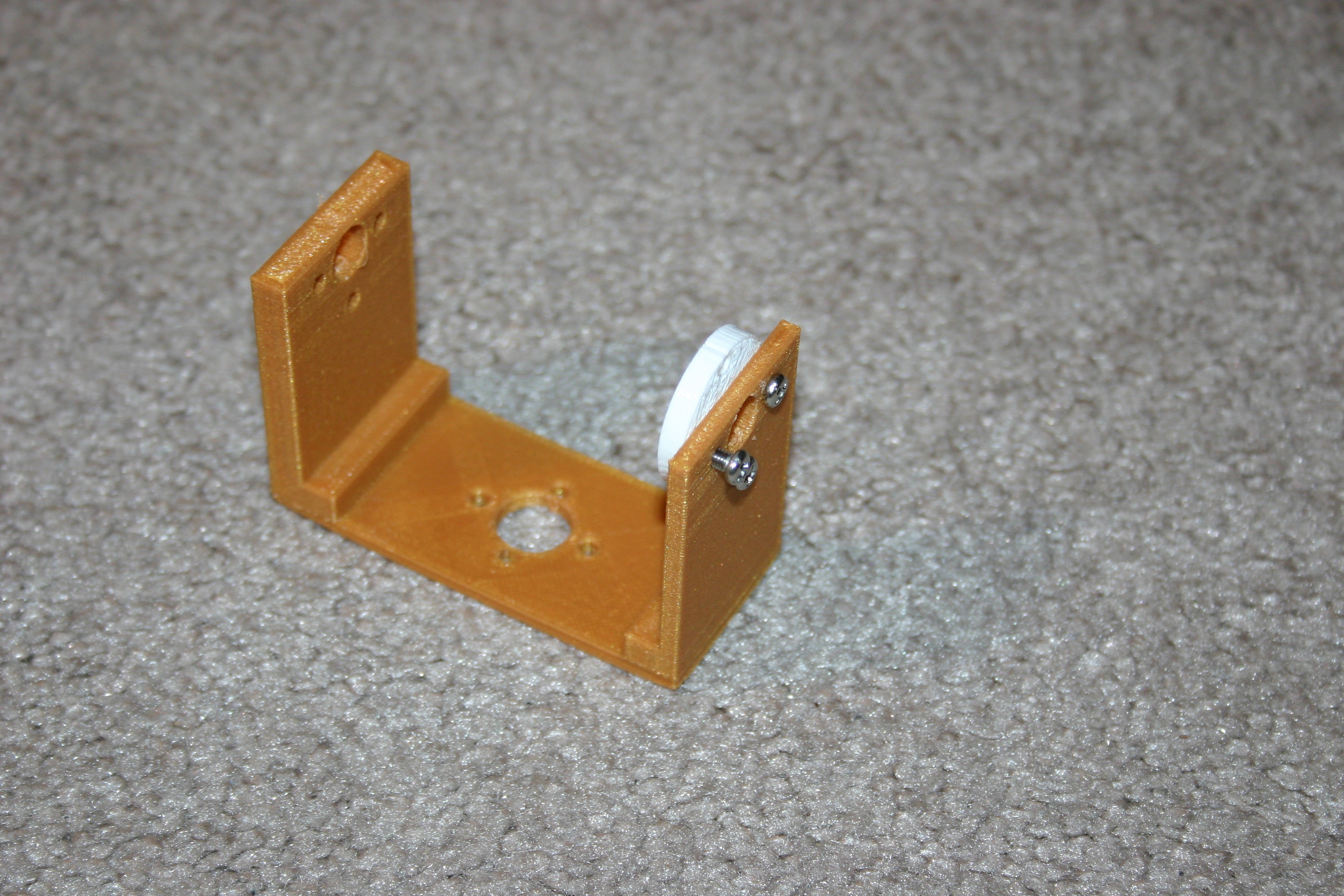
Now, to start the knee change design process. First, I measured the new servo and printed a template to see if the motor and screw holes would align.
![]()
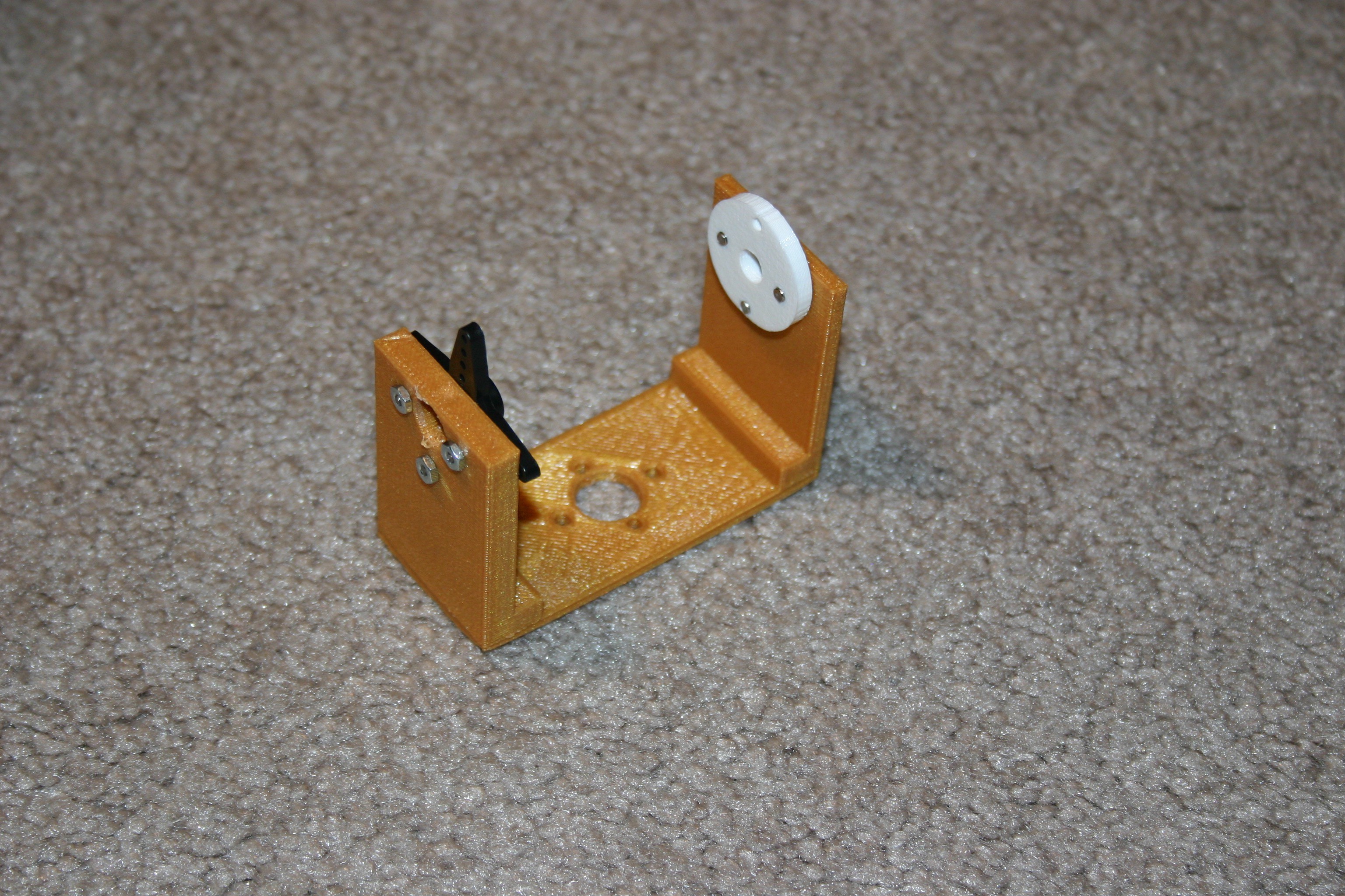
Too precise! The motor has to be "angled in" to fit the cable; thus the length of the slot must be slightly larger than the length of the servo body to work.
![]()
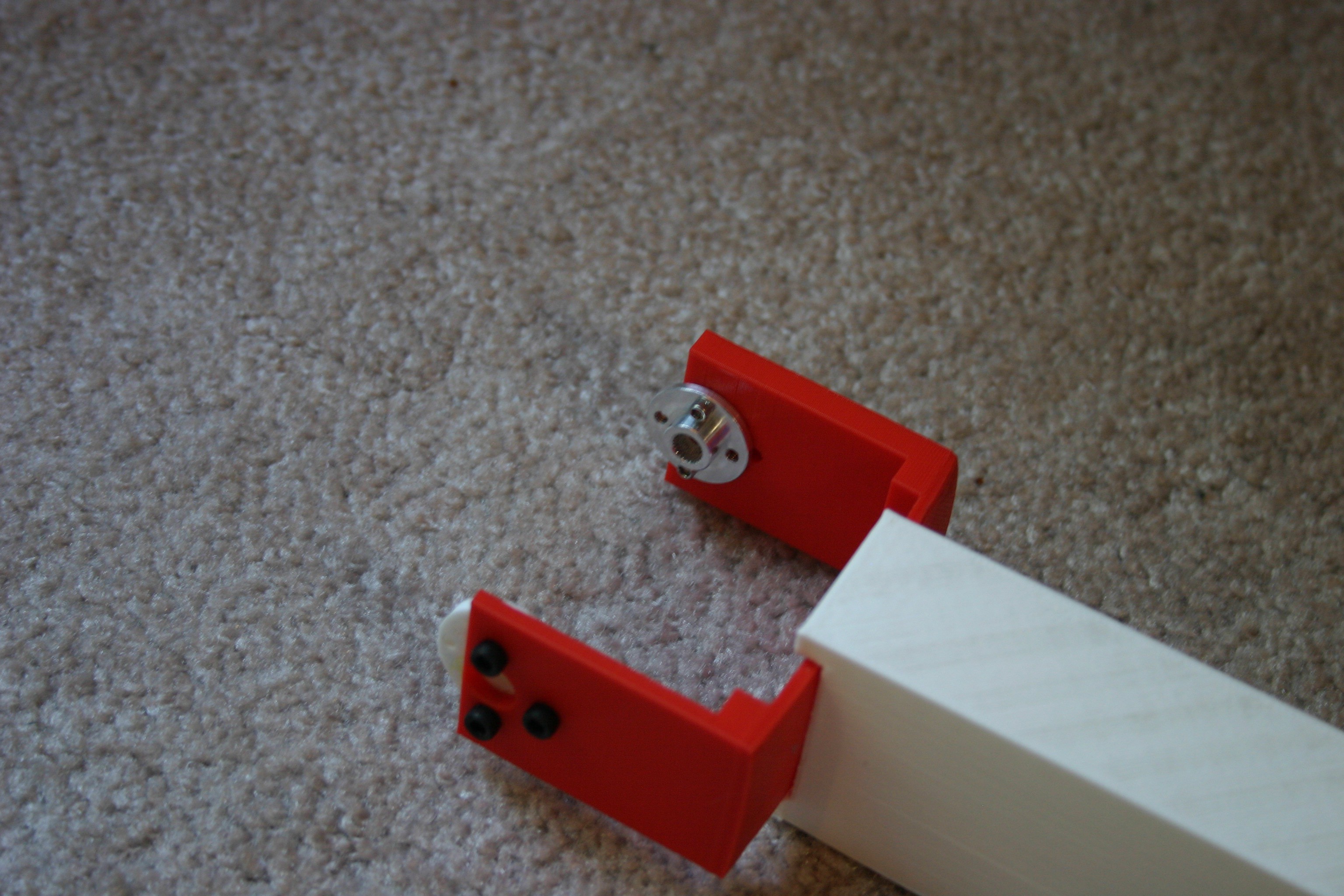
Just adding a millimeter here and there resulted in a hole too large. Time to adjust again and reprint the template.
![]()
This is a good fit--now to add some depth and sides.
![]()
That looks good. Next, it needs to blend with the upper leg attachment bracket.
![]()
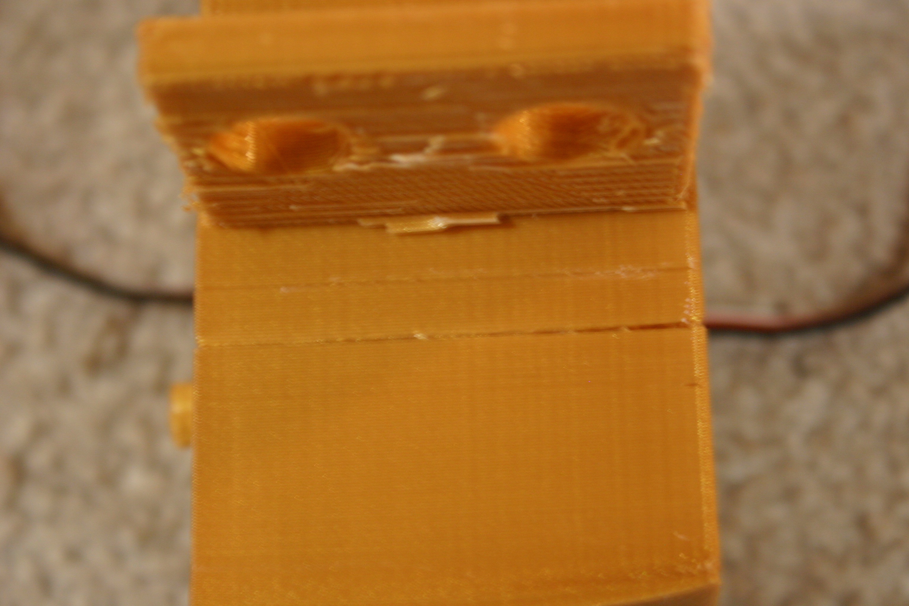
During the 4 1/2 hour print, filament on the spool was tangled and a weak layer was printed in the bracket. Time to change filament and print again.
![]()
This looks pretty good.
![]()
I think this will work--of course I'll have to create a new receiving bracket for the lower leg.
-
The Forces Are Not All With Me
03/26/2018 at 20:22 • 0 commentsMy experimental results were confusing, so I needed a better grasp of the forces at work.
The front end of the dog would stand easily enough. The rear end refused--either the feet would slide, the entire dog shift rearward or some other odd combination. Tests indicated that the rear legs could produce the same torque as the front legs, so what was going on?
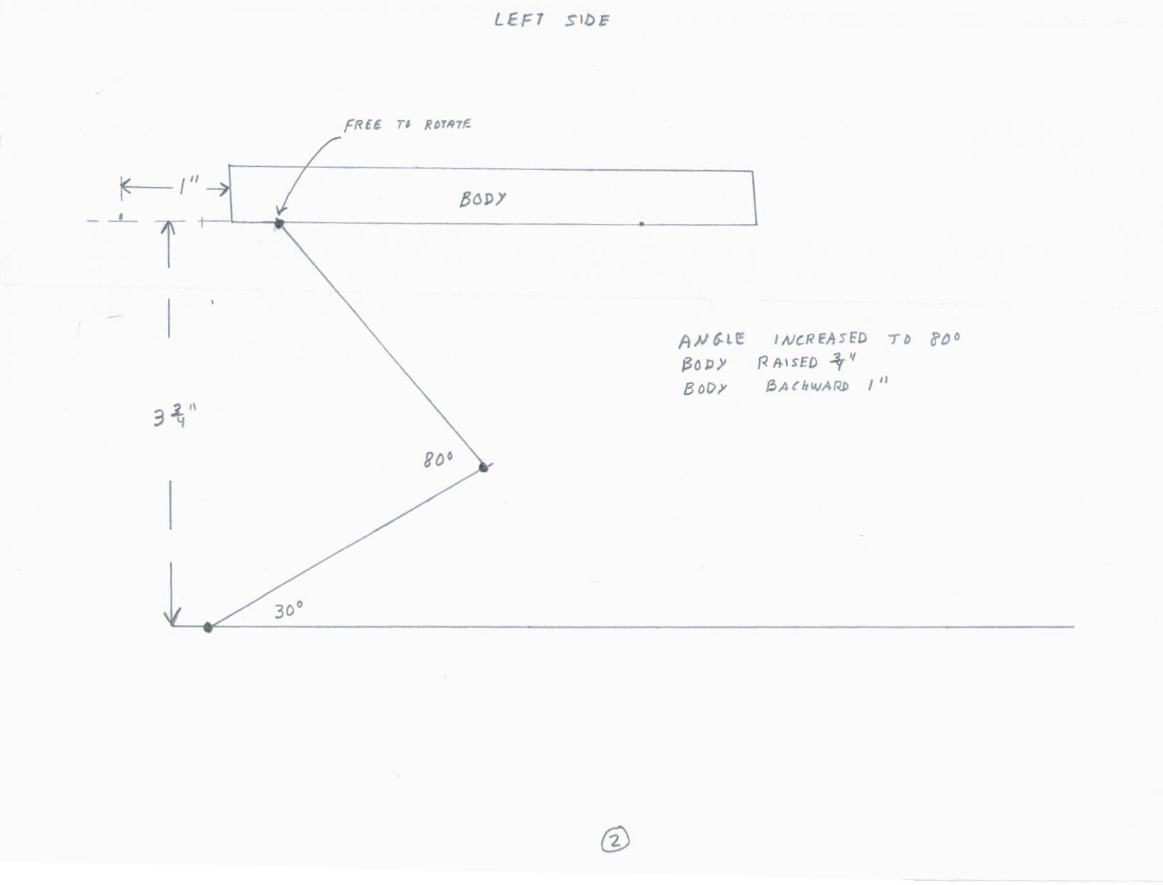
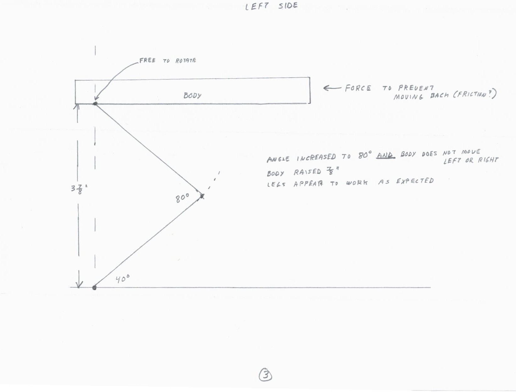
I decided to assume some experimental circumstances. From the left side, suppose that the left front foot is fixed to the ground and the shoulder is free to rotate. Change the knee angle from 60 degrees to 80 degrees.
![]()
The body should rise and move backward.
Now, same imaginary experiment, but don't let the body move rearward--let the friction of the rear legs or some other force prevent rearward movement.
![]()
The body rises and the leg "looks" the way I thought it would.
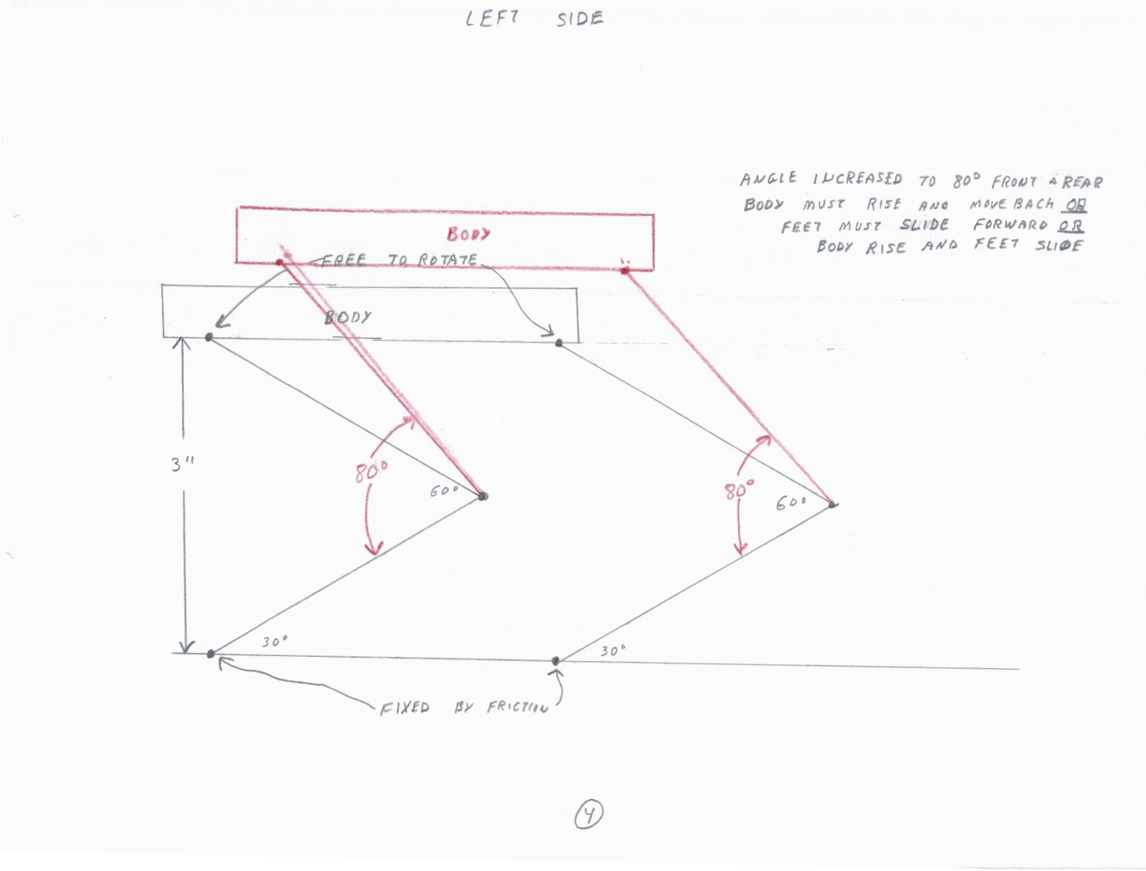
Now, looking at the left side, let's assume the front and rear legs are operational--feet fixed and shoulders free to rotate.
![]()
The body must rise and move rearward or the feet must slide forward or some combination.
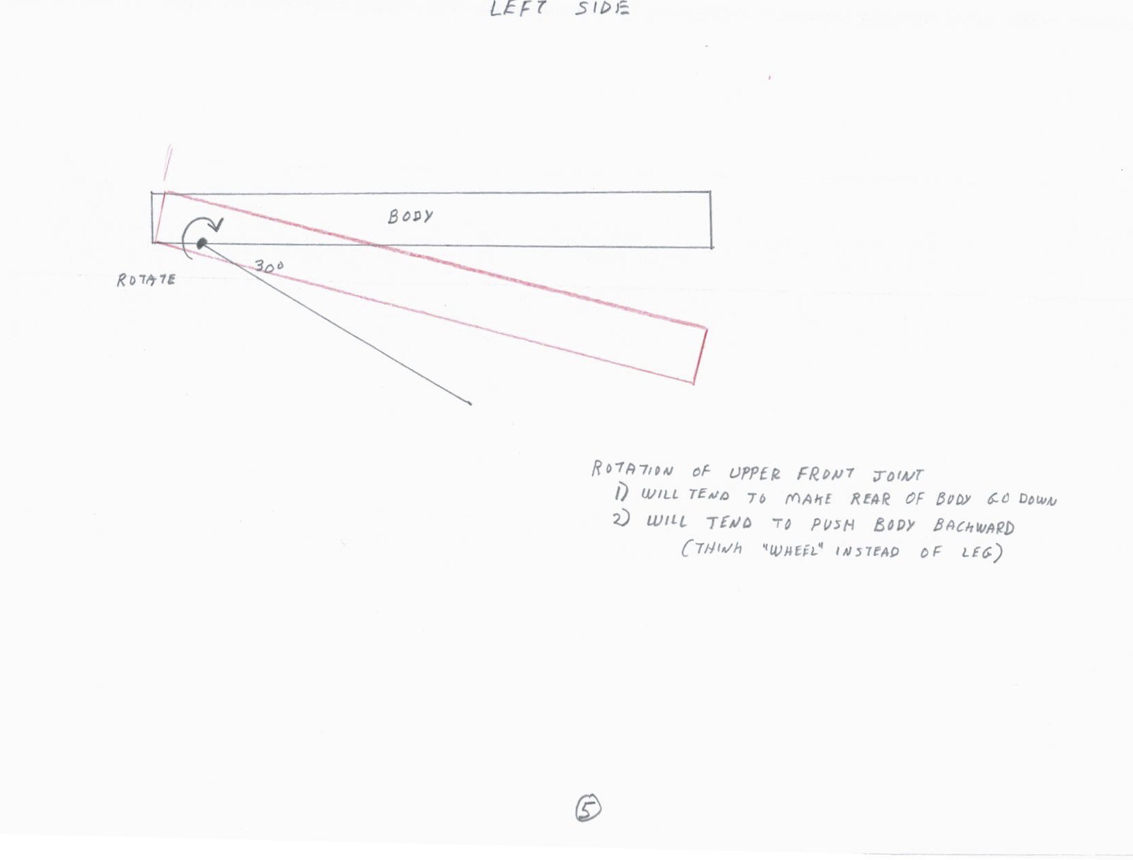
Now, another thought experiment. From the left side, let's look at the front shoulder joint and assume that the shoulder rotates in the clockwise direction.
![]()
This will tend to make the rear of the body go down and it will tend to push the body backward (think wheel instead of leg and the "foot" (wheel) does not slide).
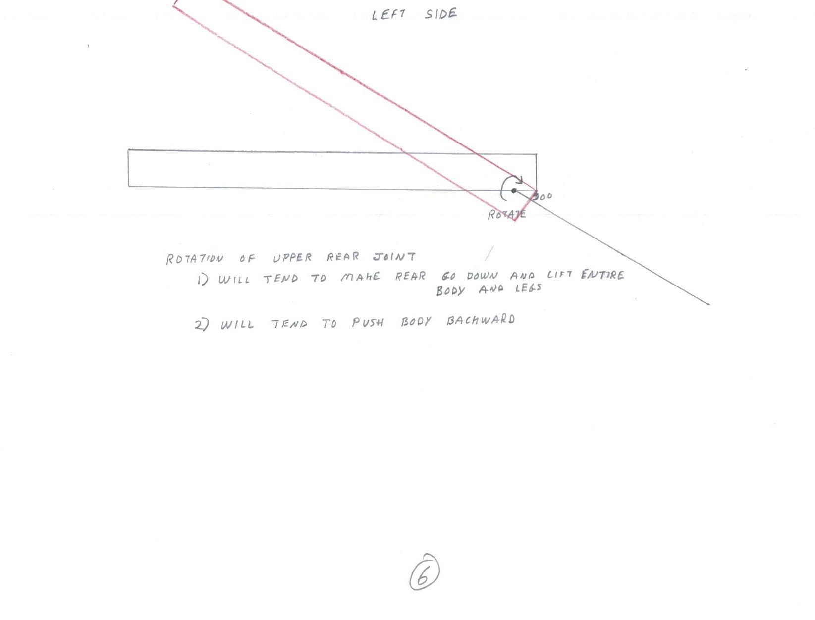
What happens when the rear shoulder joint turns clockwise?
![]()
This will tend to make the rear go down and the front rise up while pushing the body rearward.
Everything seems to push the body backward and a couple of things work to push the rear end toward the ground.
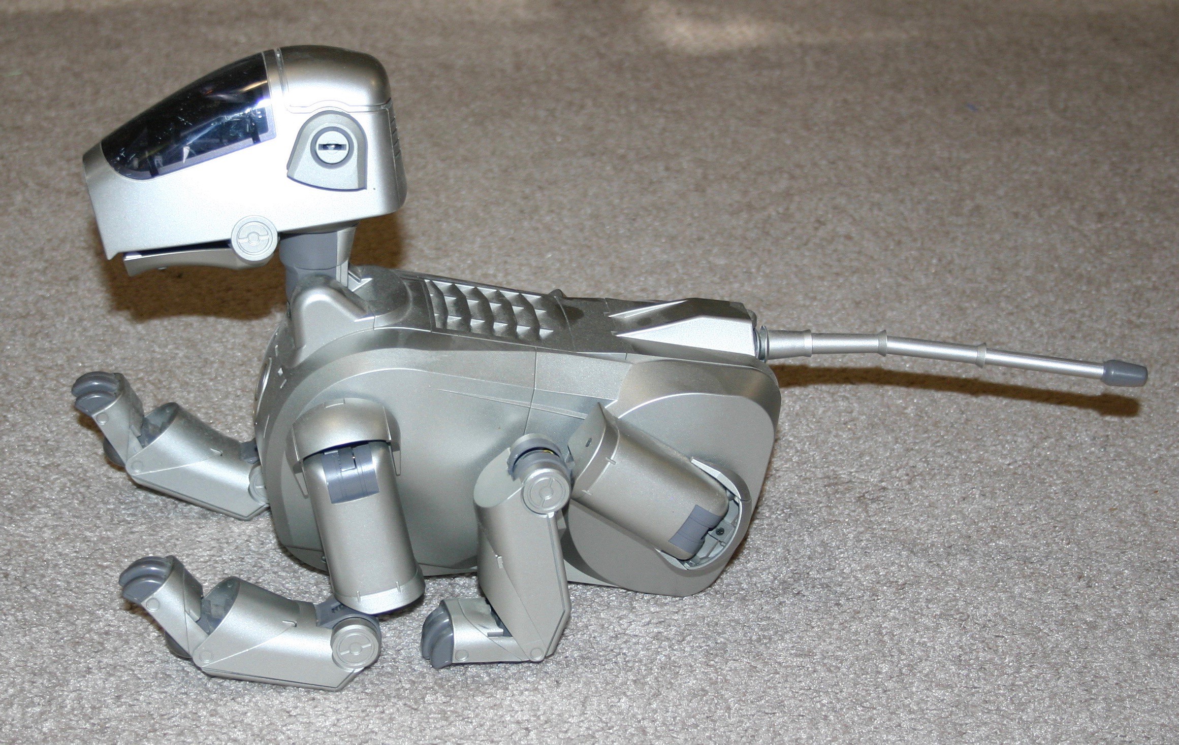
Now, I'm pulling out my ace--in 1999 I purchased a Sony robot dog, Aibo.
![]()
To stand, Aibo's left front shoulder turns clockwise and his left rear shoulder turns counterclockwise.
I flipped the rear legs on my dog (right rear became left rear; left rear became right rear) and he was able to stand.
This doesn't explain how Boston Dynamics gets their dog to stand--but that's not my problem. Note in the "Details" that the "Anymal" dog uses the opposing rotation method.
For general information, while tearing my dog apart I noted that a leg assembly (including three 67 gram motors and two steel bearings) comes in at 808 grams. I need to reduce this in a redesign--just another thing to keep in mind.
-
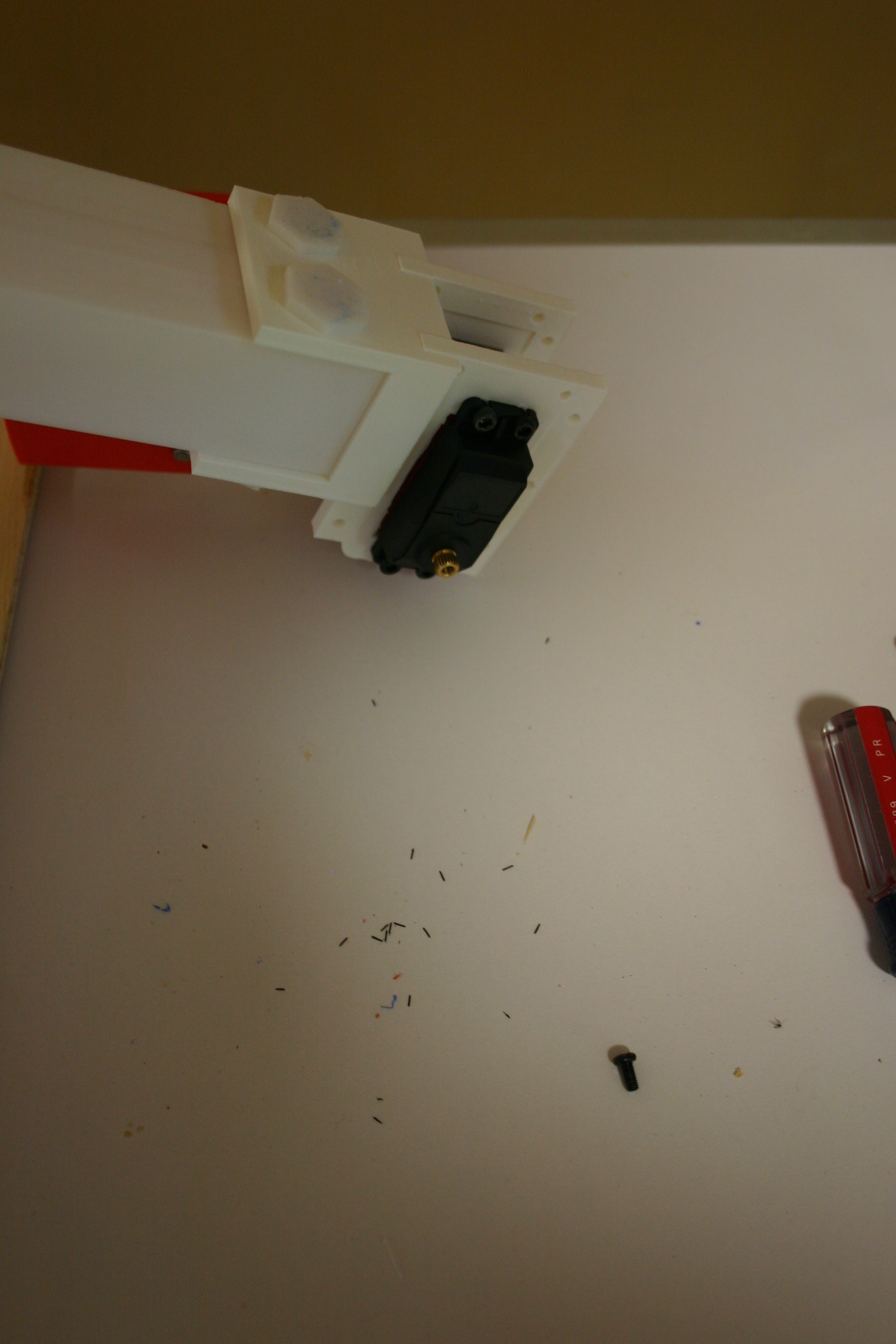
Torque Damage and Sitting
03/16/2018 at 19:21 • 0 commentsThe right rear leg quit--I figured a motor was cooked, but the problem turned out to be a stripped out plastic servo horn (note the bits of black plastic on the table).
![]()
I pulled the leg off to remove the old plastic horn.
![]()
The new aluminum horn fits the servo motor, but it's a bit dicey attaching the new horn to the 3d printed leg joint. It kind of works, but I'll have to redesign the joint and rework all the legs.
![]()
Changing two of these servo horns allowed enough control that I could attempt a sitting position.
-
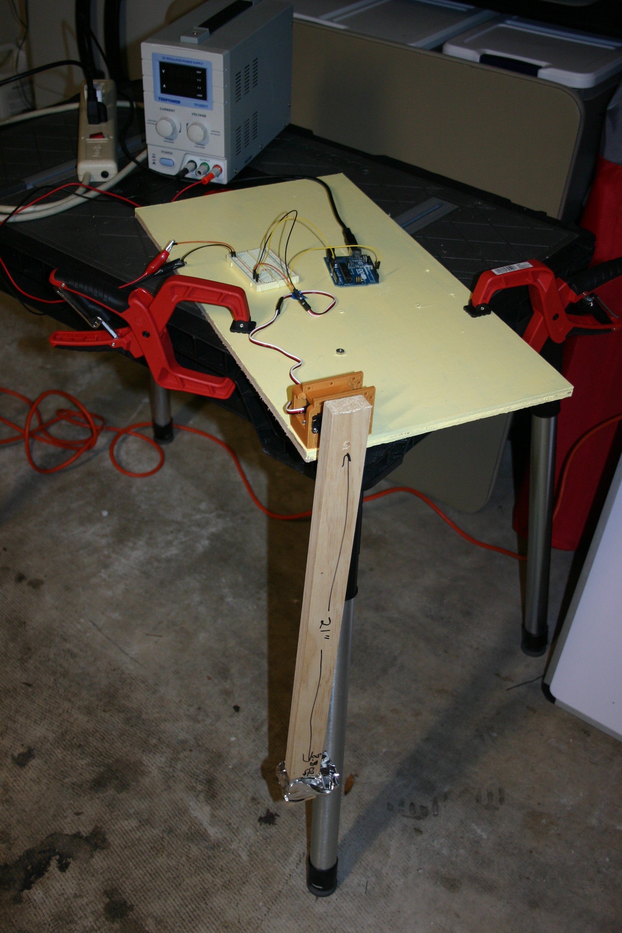
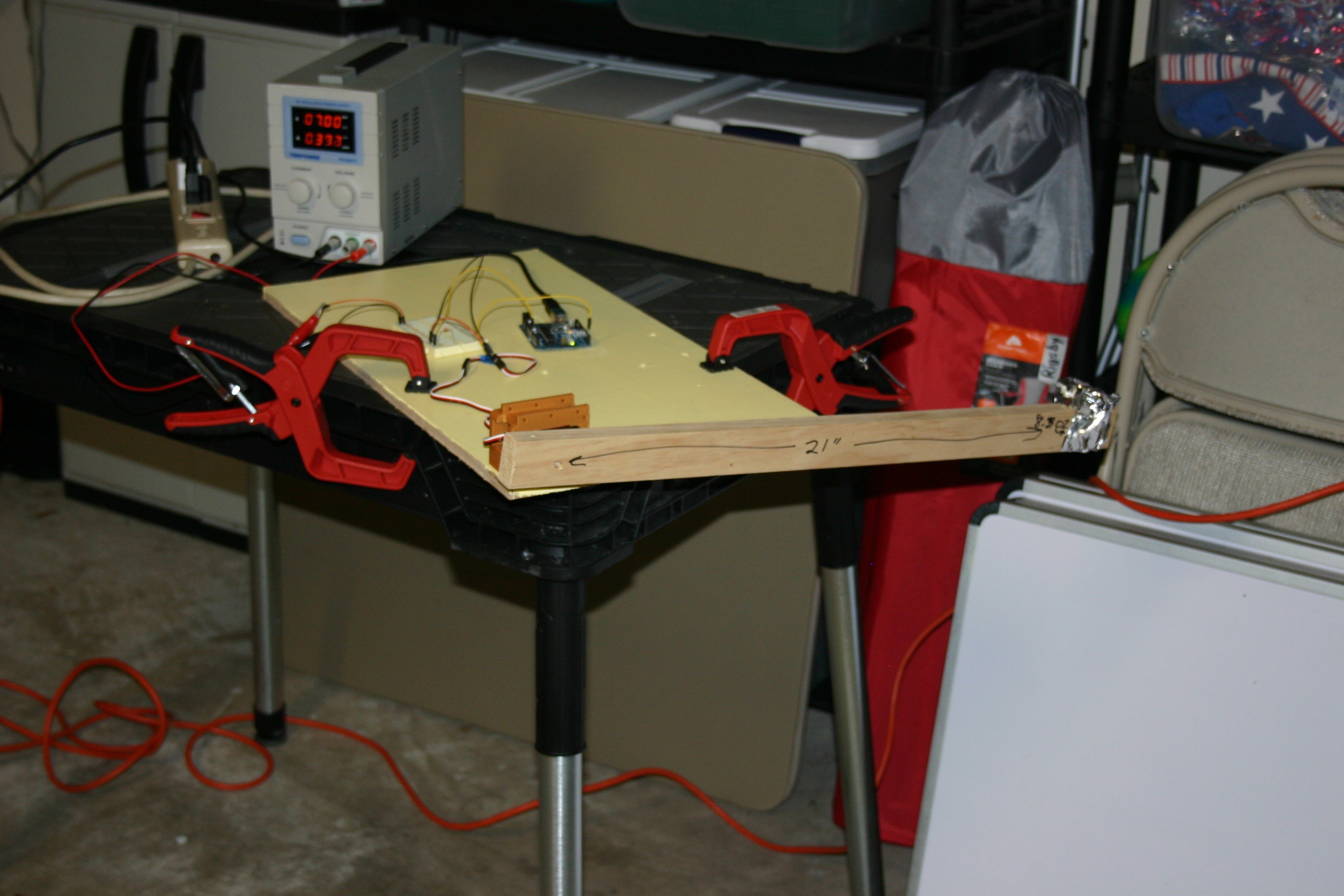
Testing Servo Motor Torque
03/13/2018 at 18:59 • 0 commentsThe servo motors I am currently using claim to have a torque rating of 20 kg-cm (277.6 oz-in). Rather than just accepting an advertised claim, I thought it would be a good idea to know if the motor could really produce such torque.
My test rig involves a 1" x 2" pine board attached to a servo motor. At a distance of 21" from the servo shaft, I have taped 8.3 ounces of lead weight. Twenty-one inches multiplied by 8.3 ounces yields 174.3 ounce-inches of torque. The 8 ounce wood arm (assuming even distribution and that the center is 11 inches from the arm) contributes 88 ounce inches to the torque required. Adding 174.3 to 88 yields 262.3 ounce inches of torque. I didn't play with weights to find the absolute max, but I have no reason to question the 277.6 oz-in advertised.
![]()
Under load, it looks like this:
![]()
As an interesting side note, the current required to hold the arm horizontally (at 7 volts) is about .4 amps. If the current limit on the power supply is less than 2.5 amps, the servo motor won't rotate the arm.
-
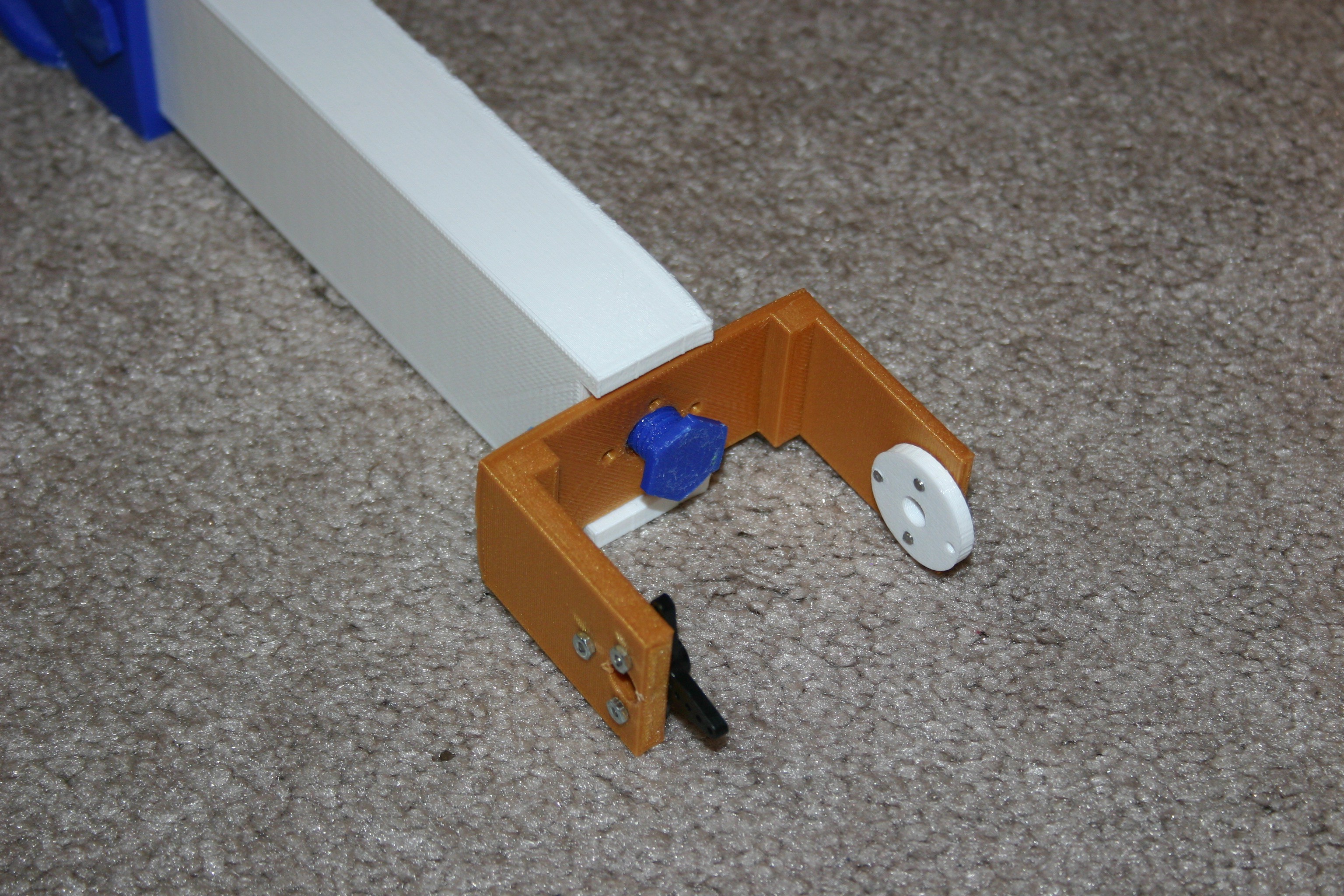
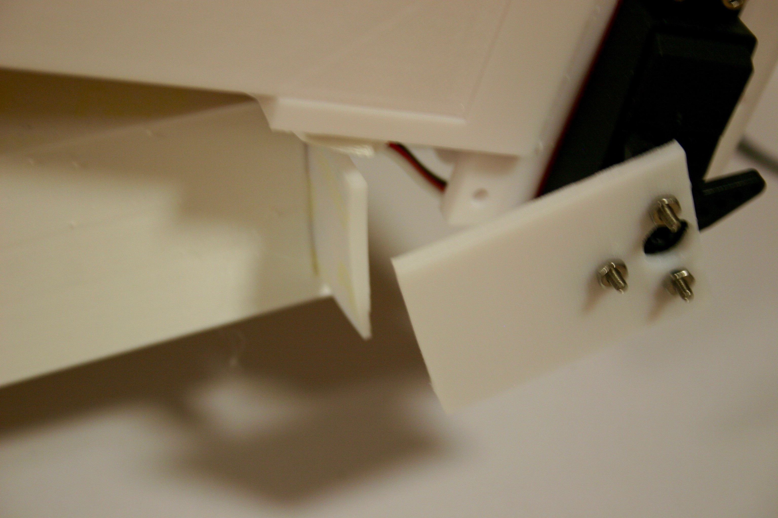
Repair Broken Joint and Stop Slipping
03/12/2018 at 20:57 • 0 commentsI printed a stronger joint piece and replaced the broken and damaged joints.
This photo shows the replacement of the "back bearing" for the servo motor.
![]()
This is the installation of the servo horn.![]()
This is the attachment of the servo piece to the leg.
![]()
The servo attachment piece has to be fastened to the servo motor using the servo screw.
![]()
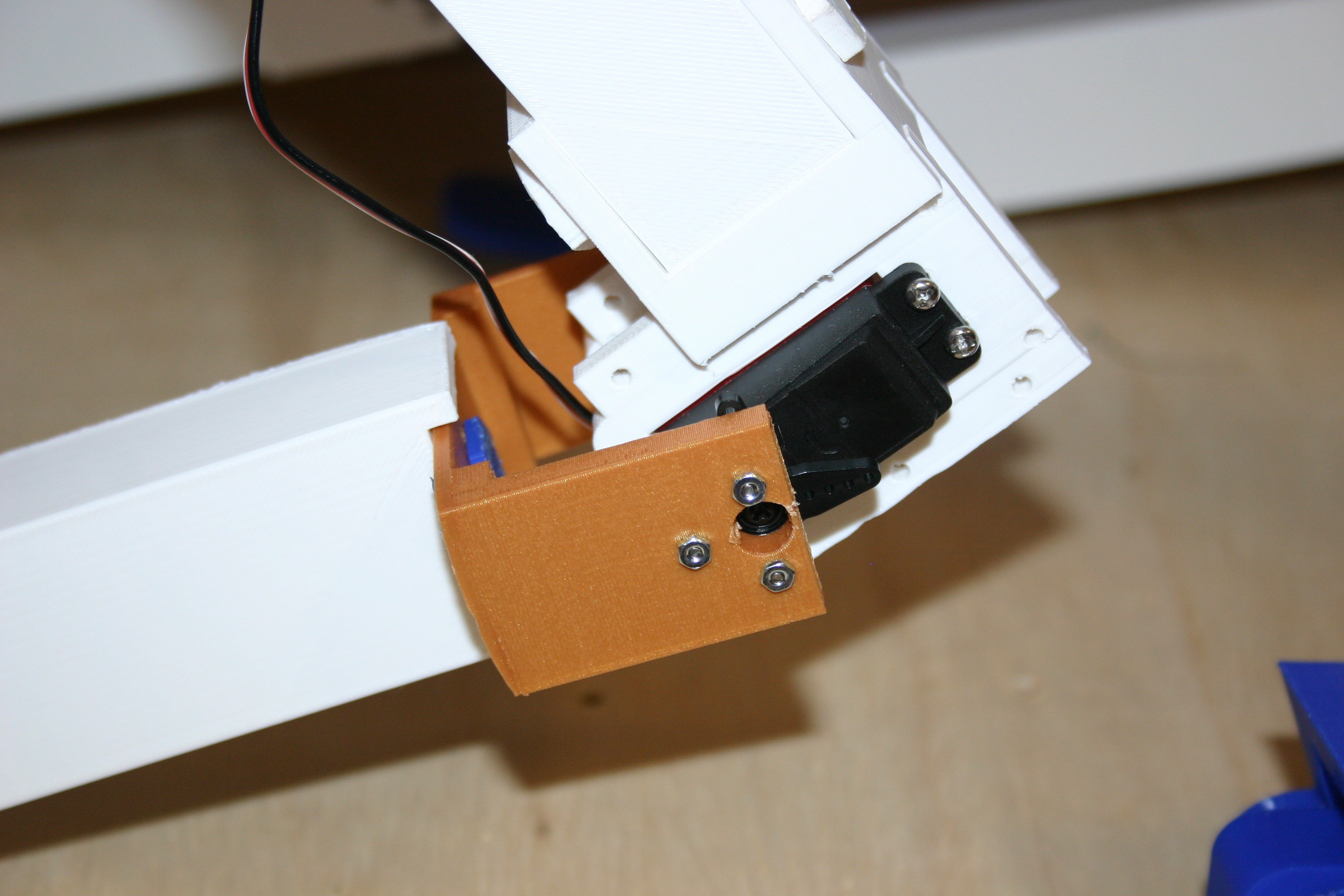
Next, I made a wider wheel, one that will not turn, to be in the foot position. Part of my trouble with standing involved the foot "moving around" instead of the body lifting.
![]()
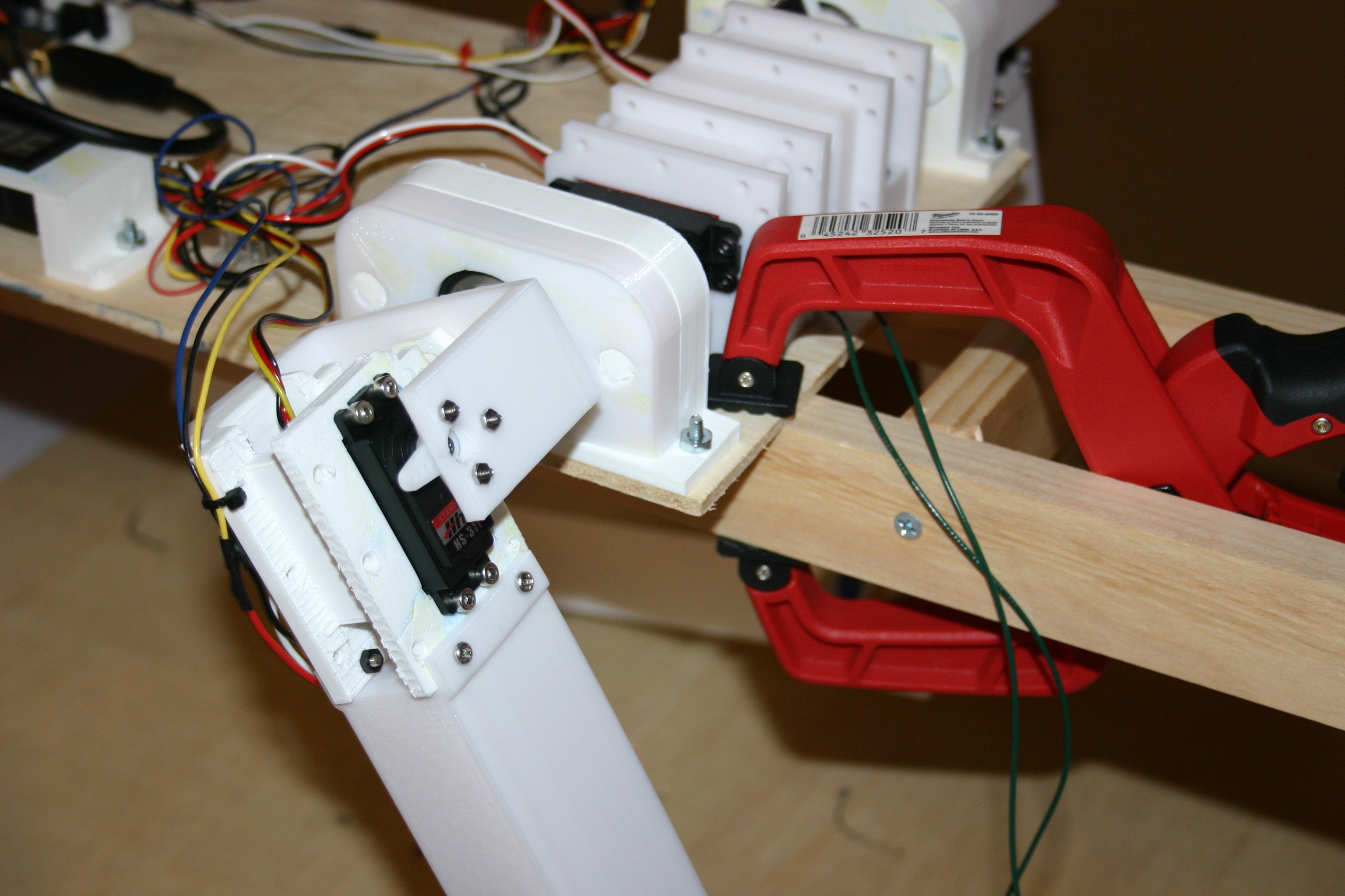
For test purposes, I clamped the body to the "hanging support" so that the body could not be lifted.
![]()
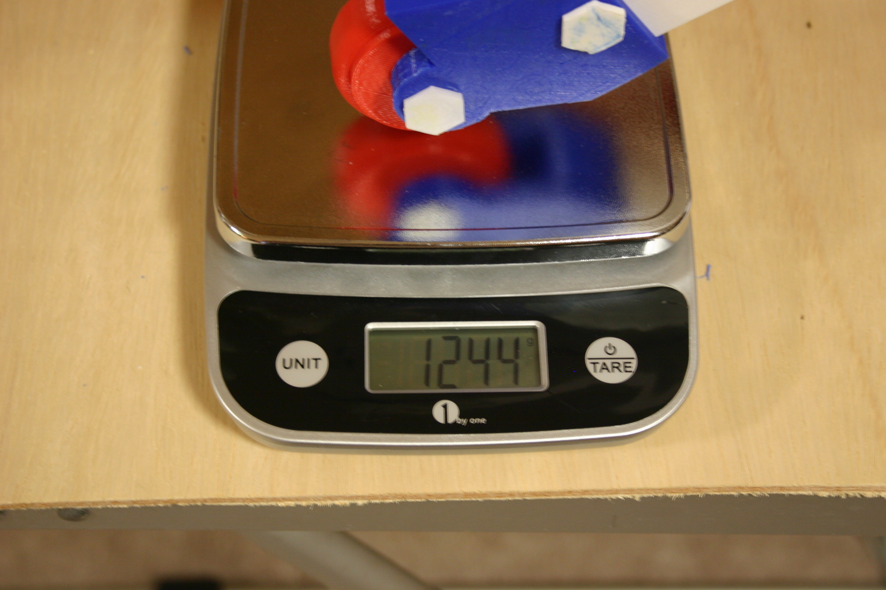
Next, I "asked" the leg to push as hard as possible. The result was 1.24 kilograms. At least under some circumstances, four legs working together should be able to lift about 5 kilograms. The body is about 1.5 kilograms, so there should be enough push to get off the ground.
![]()
I probably need some feedback and better software, but things are progressing.
-
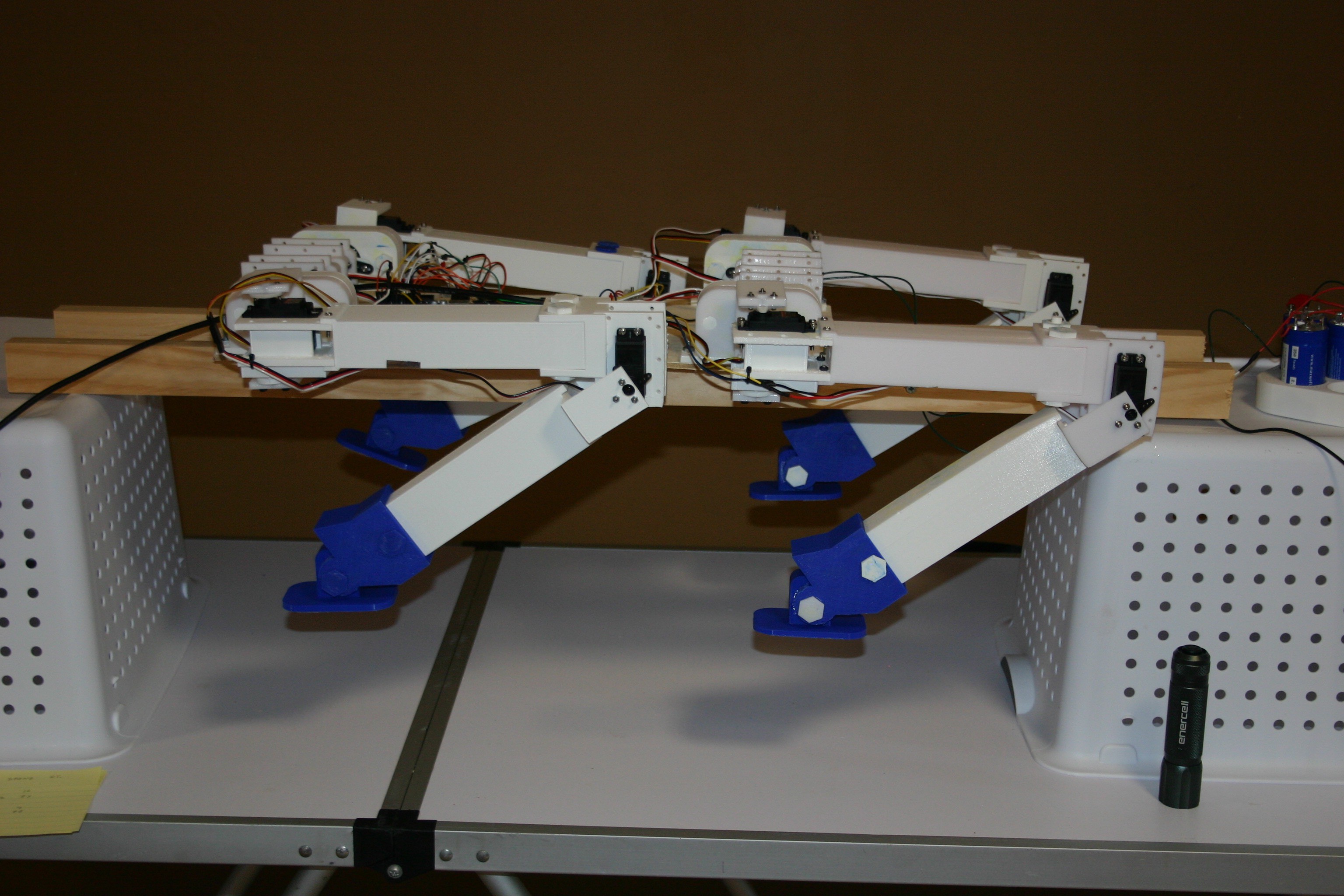
First Stand
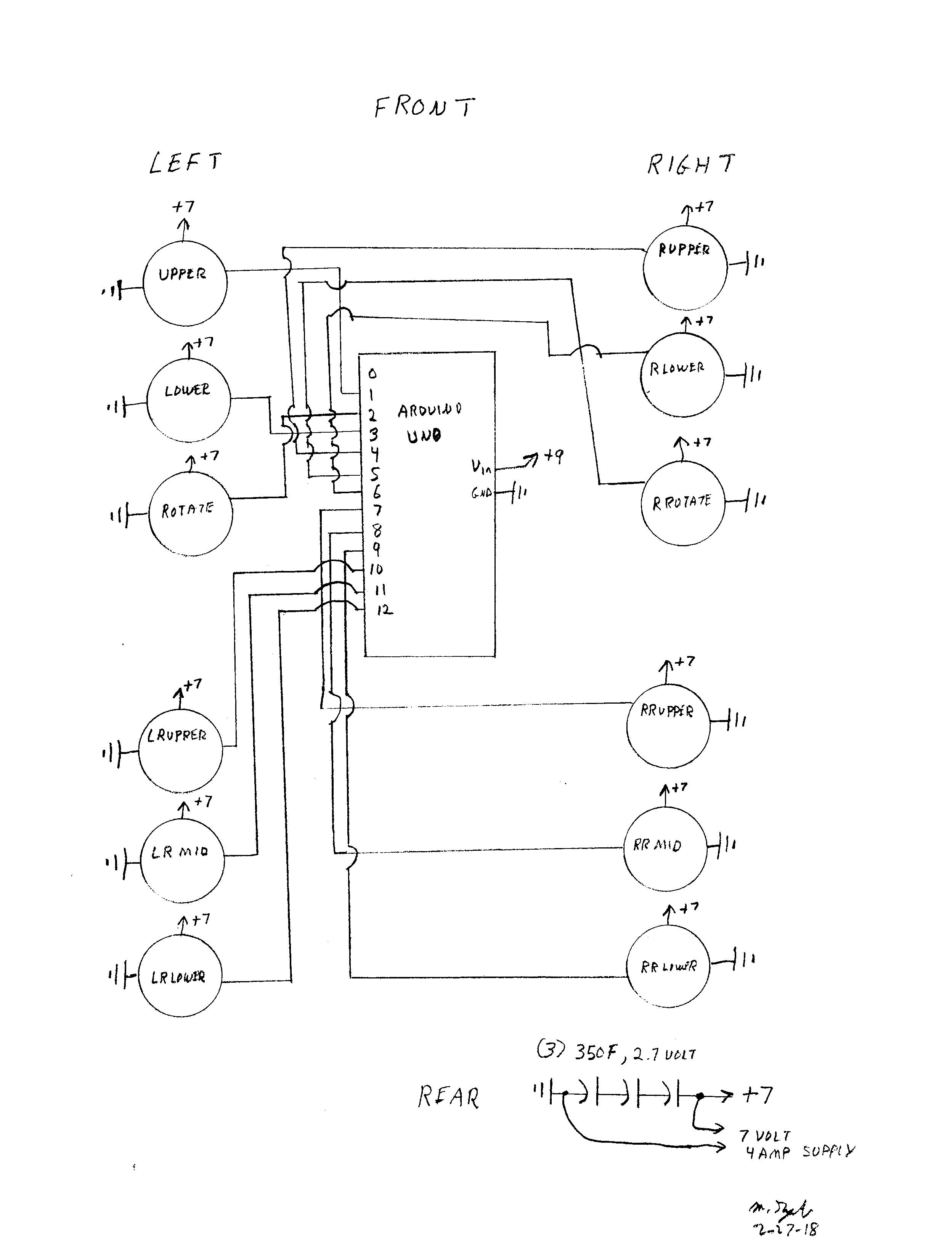
02/28/2018 at 00:19 • 0 commentsOn February 27, the first attempt at standing was made. A couple of the joints couldn't take full speed movement--we learn by trying!
To attempt the first standing test, I needed to determine the servo angles for each motor. Below is the schematic for the system.
![]()
With the mechanism suspended, I determined the servo angles for each servo.
![]()
![]()
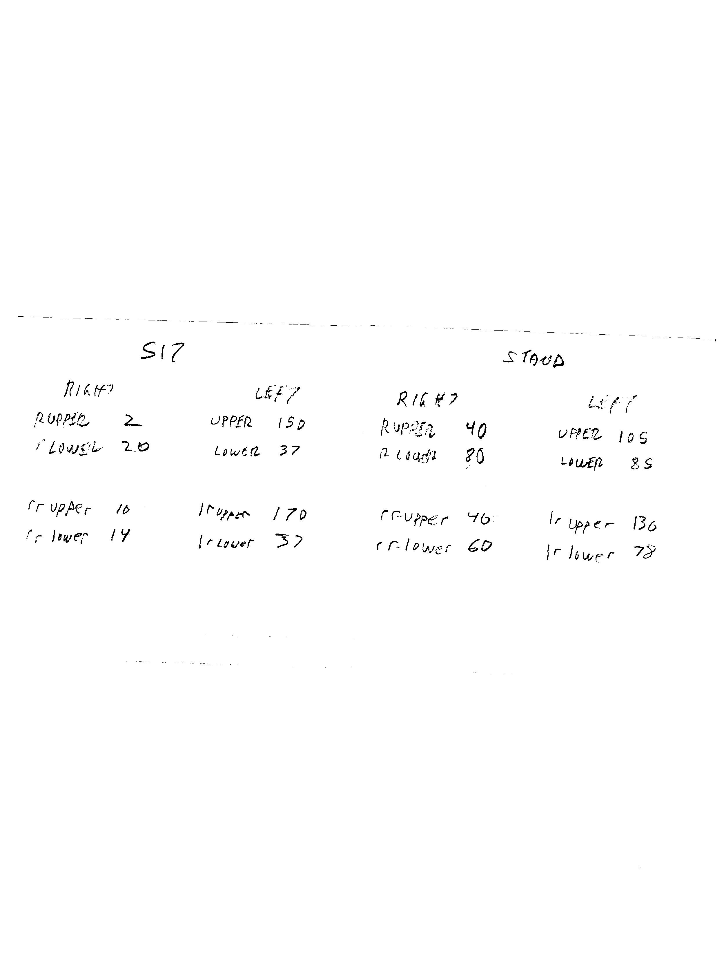
The numbers I retrieved are:
![]()
I applied those in an Arduino sketch (found in files on this project).
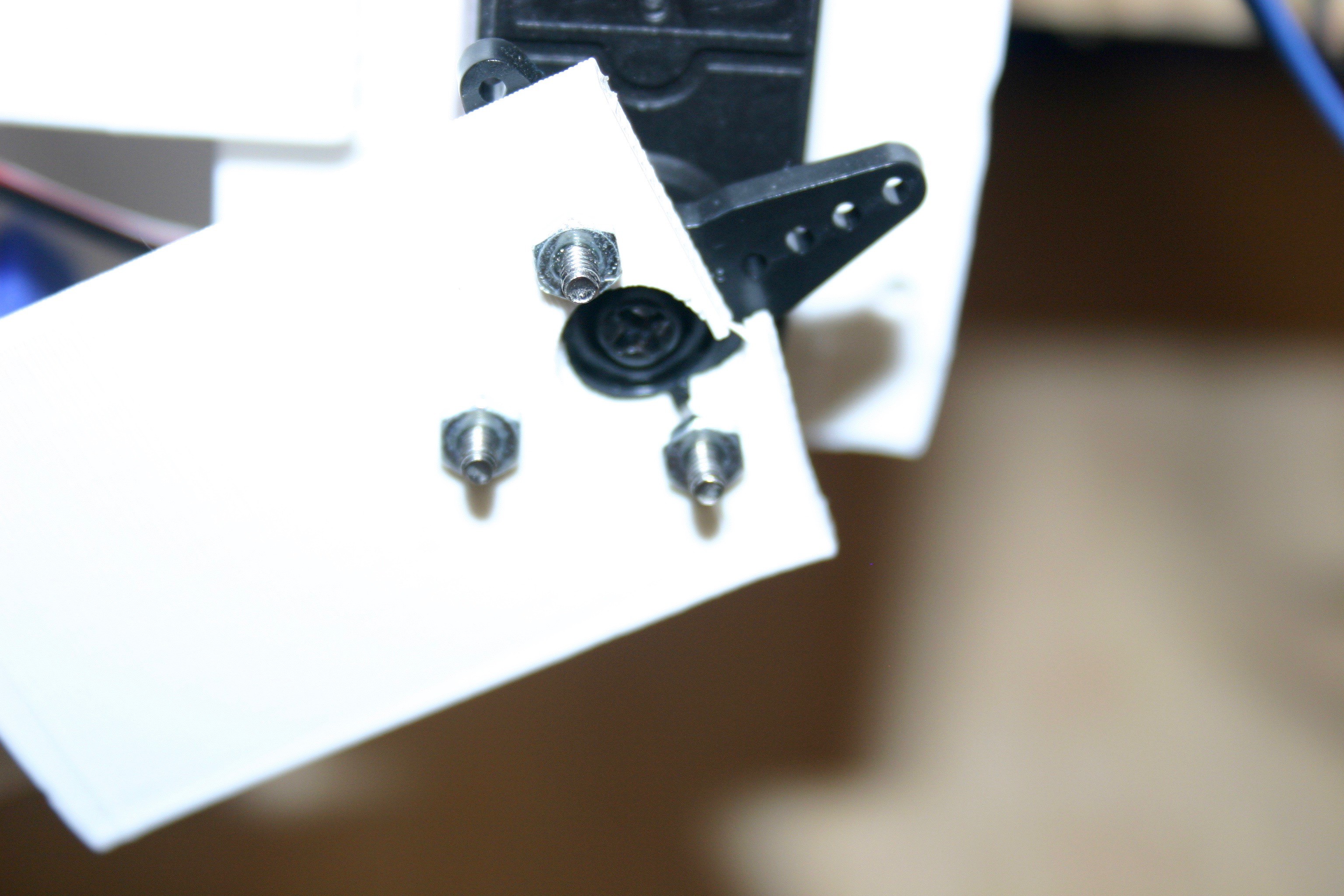
Two joints couldn't take the stress (I went full speed on the servos, kind of a worst case situation).
![]()
![]()
I'll have to redesign and install joints--then full torque ahead!
Mike's Robot Dog
Boston Dynamics' robot dog, Spot Mini is unavailable at any price. A Chinese copy is $30,000. Cut 99% of the cost and build one at home.