 Technics
In order to power up the varioscope the correct supply voltage had to be determined. I had originally assumed that supply the voltage would be 4.8V based on a what seemed to be 4 cell NiMH pack in the manual. However, performing a Google image search for "3 pin switching regulator" turned up a device that looked exactly like unidentified module (marked with the number 1 in my previous update). It turned out to be a TI PT78ST100. The data-sheet showed that it has a minimum input voltage of 9V. This would seem to rule out 4.8V as a supply voltage. Upon revisiting the HM500 user manual it actually lists the voltage under the specifications as 9.6VDC under the specifications on page 50. I missed this section when originally looking over the manual. 9.6V seems to be a much more reasonable number. The original control box probably uses an 8 cell NiMH pack and this was not obvious from the photo.
The next step is to see what happens when we apply 9.6V to the device. In order to do this I have decided to modify the data/power cable that came with the headset. It is fitted with a 10 pin LEMO K series connector at either end. These connectors are relatively easy to disassemble and it could be re-fitted if needed later. They are very high quality connectors and the matching socket costs well over $50. It didn't seem worthwhile buying one without knowing if the varioscope works or not.
I removed the connector and stripped back enough of the outer jacket of the cable to allow connection to the individual wires. The colour coding of the wires in the cable matches that of the wiring inside the the unit. This was confirmed using the continuity buzzer in my multimeter.
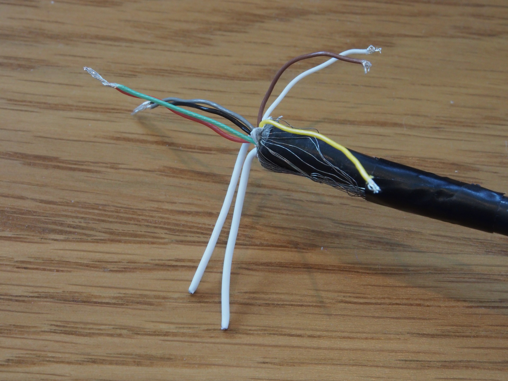
The power wires are red & green for + supply and black & grey for the - supply. These were paired together and connected up a a variable supply which has been set for 9.6V. The multimeter was connected in series to measure current and the supply switched on.
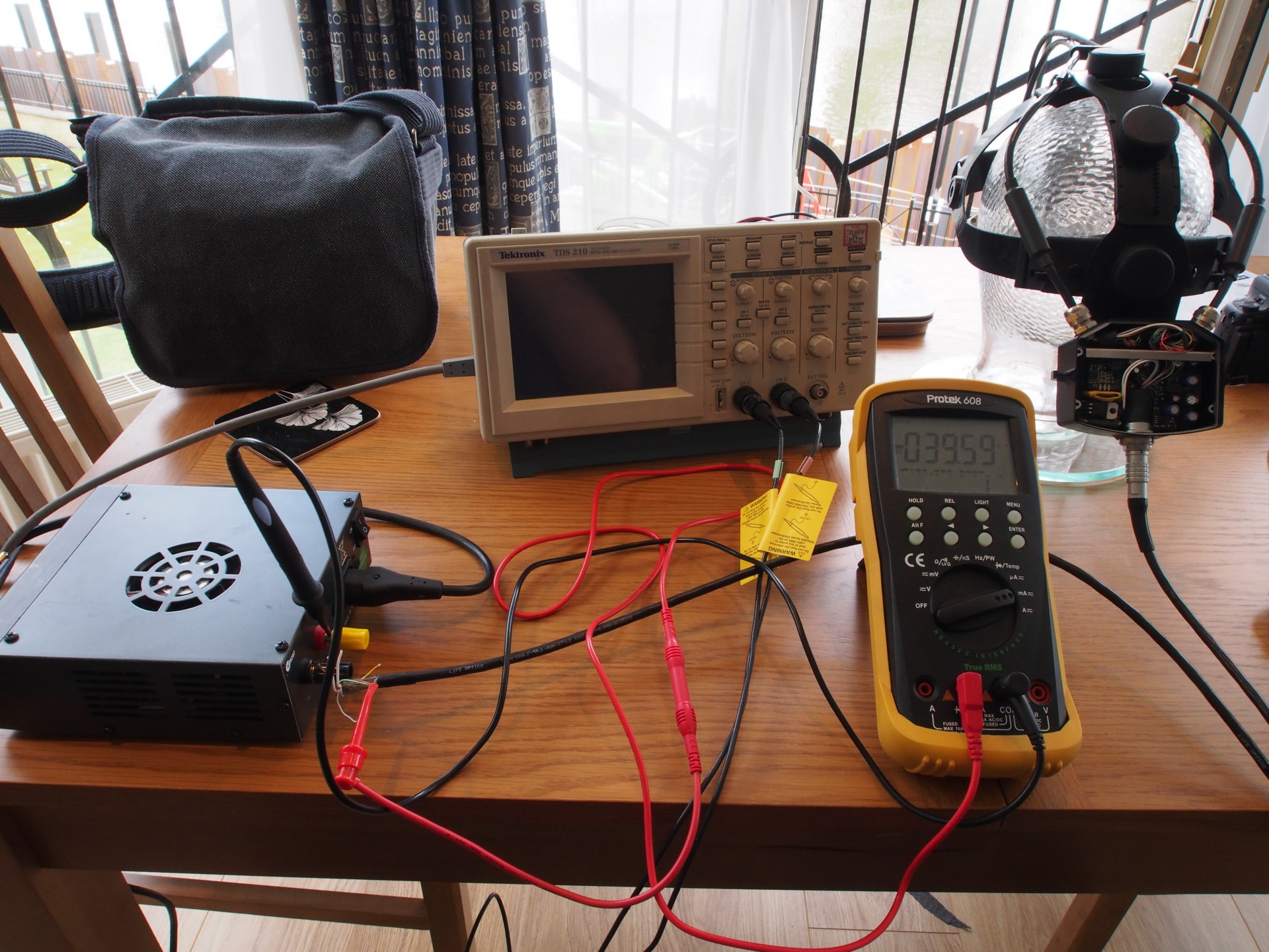
When the power is allied the device draws about 40mA at 9.6V. Not much else exciting happened. This seems like a reasonable amount of current and it doesn't suggest that the device is damaged by this voltage. No smoke or unusual smells were emitted (which is always good). The next step was to disconnect the multimeter and measure the voltage on the three mystery wires (white, yellow and brown). It turns out that all three measure 5V. This suggests that they are either digital outputs or digital inputs (with pull-ups). I turned to my scope to see if anything interesting was occurring on any of these lines.
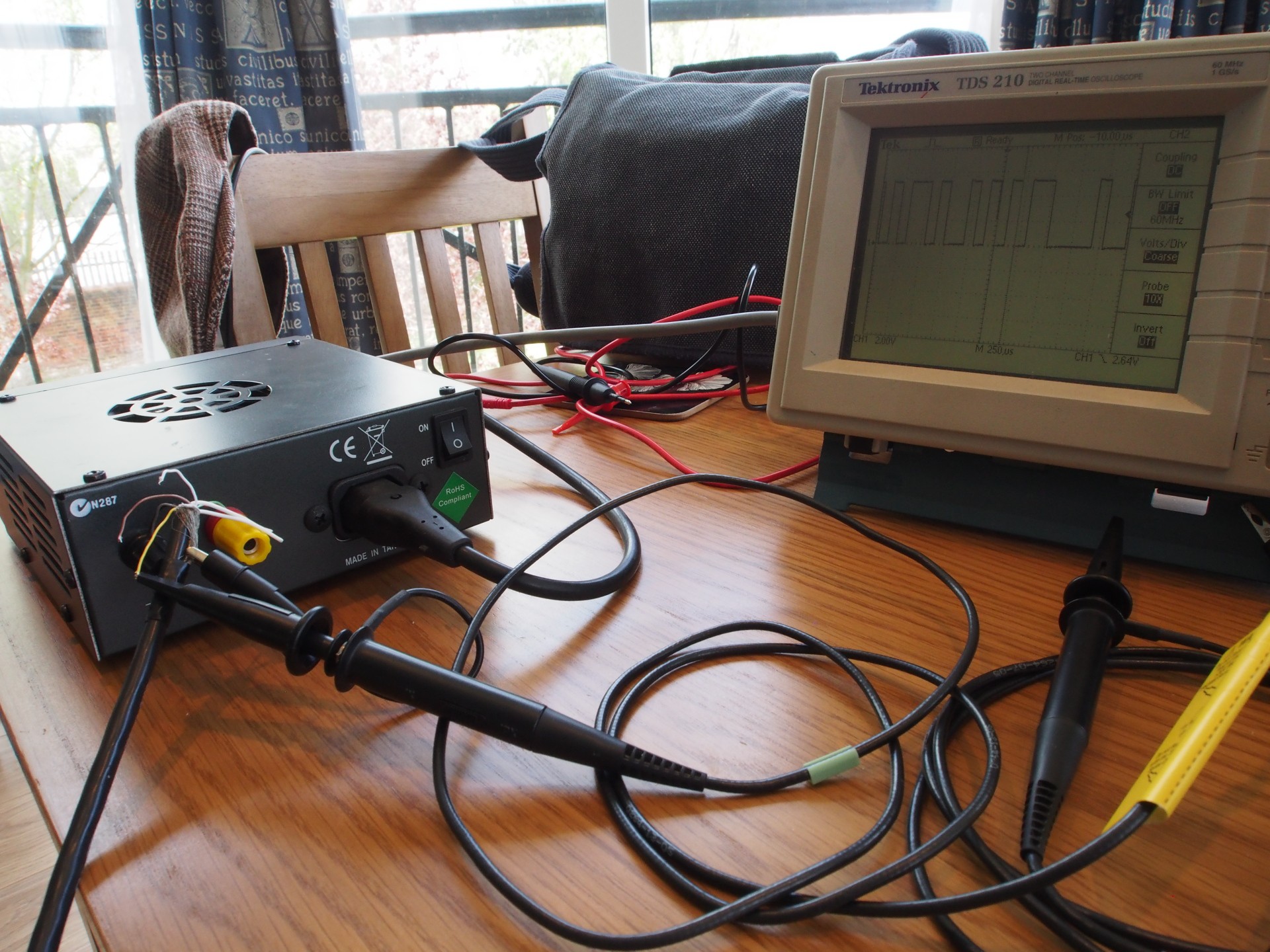
The brown and white wires do not deviate from 5V when power is applied but the yellow wire was far more interesting. When power is first applied we see something that looks a lot like TTL serial data.
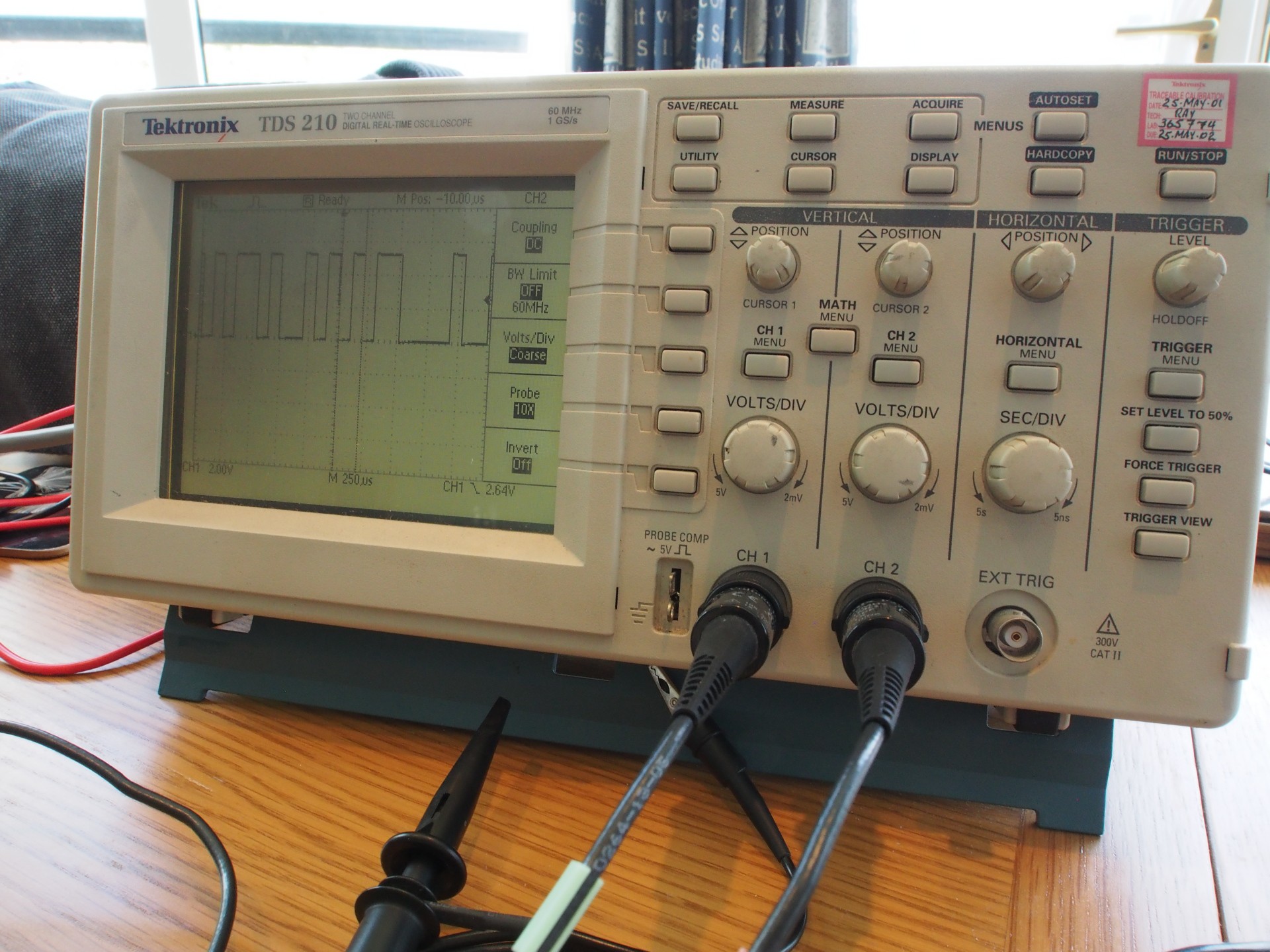
Using the cursors on the scope I measure the period of individual bits to be around 100uS. This should equate to 9600bps serial. The next step will be to hook this up to my laptop via an FTDI USB to TTL serial cable and see what the the device is sending...
Discussions
Become a Hackaday.io Member
Create an account to leave a comment. Already have an account? Log In.