 Hacker404
OK, this log will take a couple of days to get through.
I have work out the timing which is complex. The original TRS-80 had separate Character ROM and separate Video RAM.
I intend to use only one ROM (FLASH) chip and one (S)RAM chip. So the FLASH will have both the system ROM and the character pixels and needs to be accessed by both the video generator and the Z80. Like wise the RAM will have both the system RAM and the Video RAM and needs to be access but both the Z80 and Video generator.
To further complicate the matter the Video generator need to first access RAM to get the character number and then access the ROM to get the pixel arrangement that has to go to the screen.
And if that all isn't enough ... in the original TRS-80, the Z80 had access priority and this caused some screen flicker with video access. As this build will have only one RAM chip then this flicker would happen whenever ANY RAM is accessed ie not just Video RAM. On top of that the same would happen with conflicts of access to the ROM for both the CPU and the Video characters.
So I have to solve this by timing it out so that access to both RAM and ROM doesn't clash which will be hard to do with Video clocking out pixels at 25MHz (HSVGA) and a CPU running an irregular access pattern at a base clock about 2MHz.
For a test bed for this part of the project I have decided to go with Wire-Wrap after someone mentioned that Wire-Wrap will fit normal pin headers. I order a wire-wrap tool for about $35. I still had wire-wrap wire as I use that for repairing PCBs.
Finding wire-wrap sockets is too hard now and I have a lot of breakout boards that wont fit standard sockets anyway so I decide to use ZIF sockets as they're as cheap as wire-wrap sockets anyway.
Here is what I have put together so far -
Top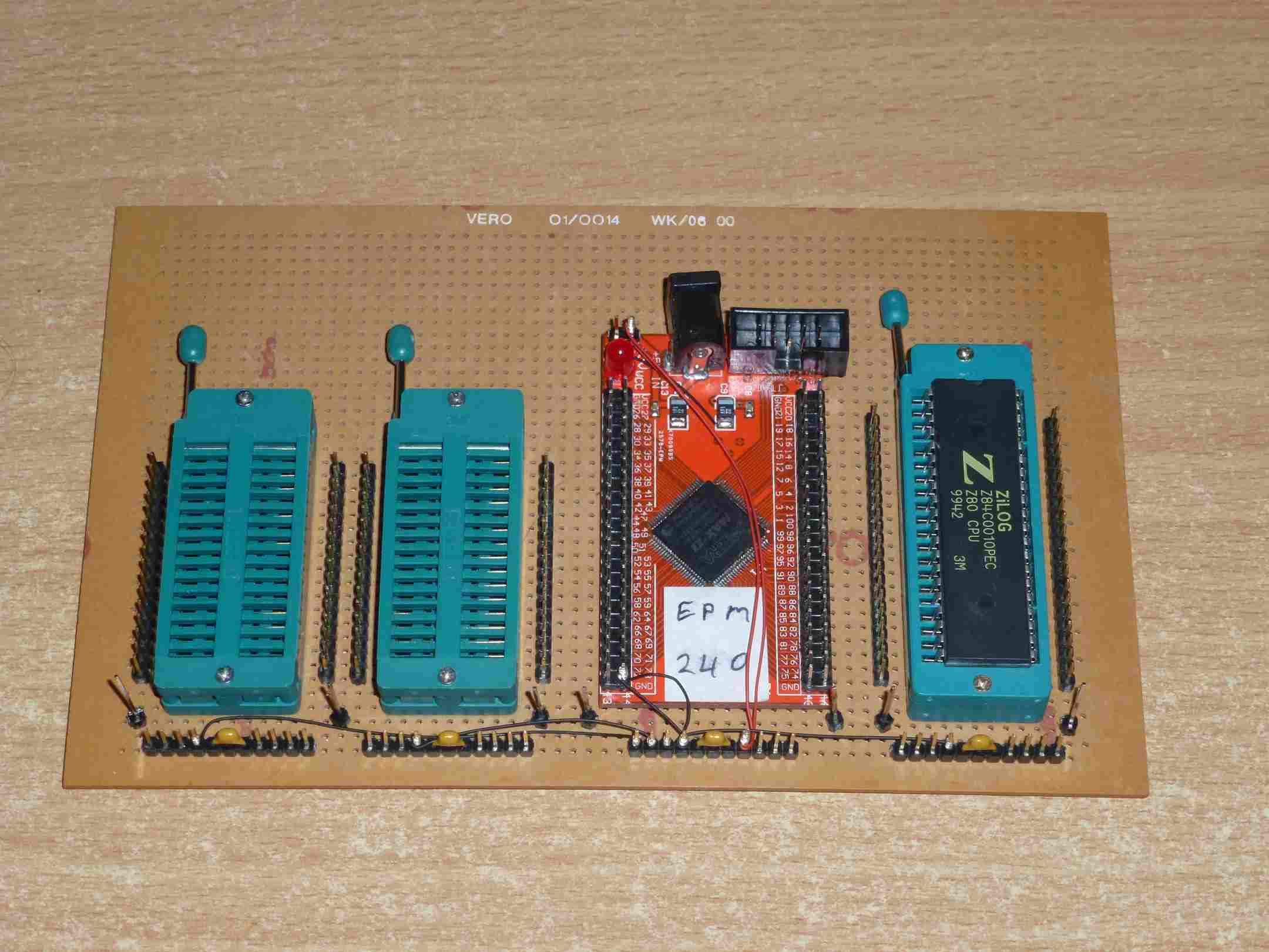
Bottom
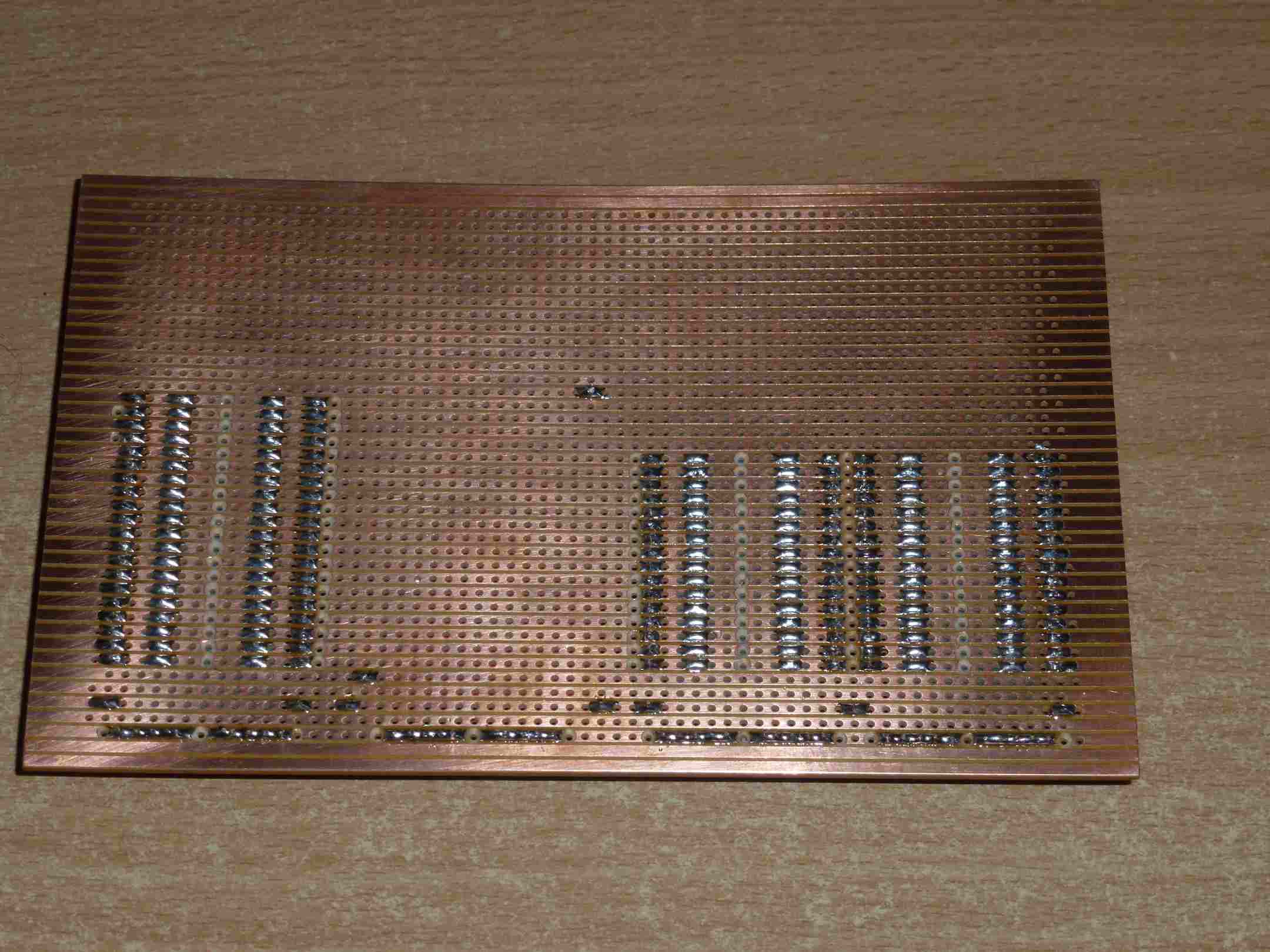
I started some wire-wrapping and it seems to go ok.
The Z80 pictured is a fake from China (ebay) you can tell by the color and brightness of the printing on top. It marked as a 10MHz chip but it's probably just a Z80, Z80A or Z80B. It will probably work fine at ~ 2MHz.
I decided to use a EPM240 CPLD as it has enough logic for this part easily. Problem is that it only has 80 IO. So roughly 40 IO for the Z80, 35 IO for the RAM/ROM and 3 or so for VGA.
That means that there is basically no IO pins left for the expansion port keyboard cassette etc. So I make have to tack another board on to the right of this one later.
OK ... I am off to some VHDL and hope to be back in a couple of days.
Discussions
Become a Hackaday.io Member
Create an account to leave a comment. Already have an account? Log In.