 Marc Schömann
Short Description
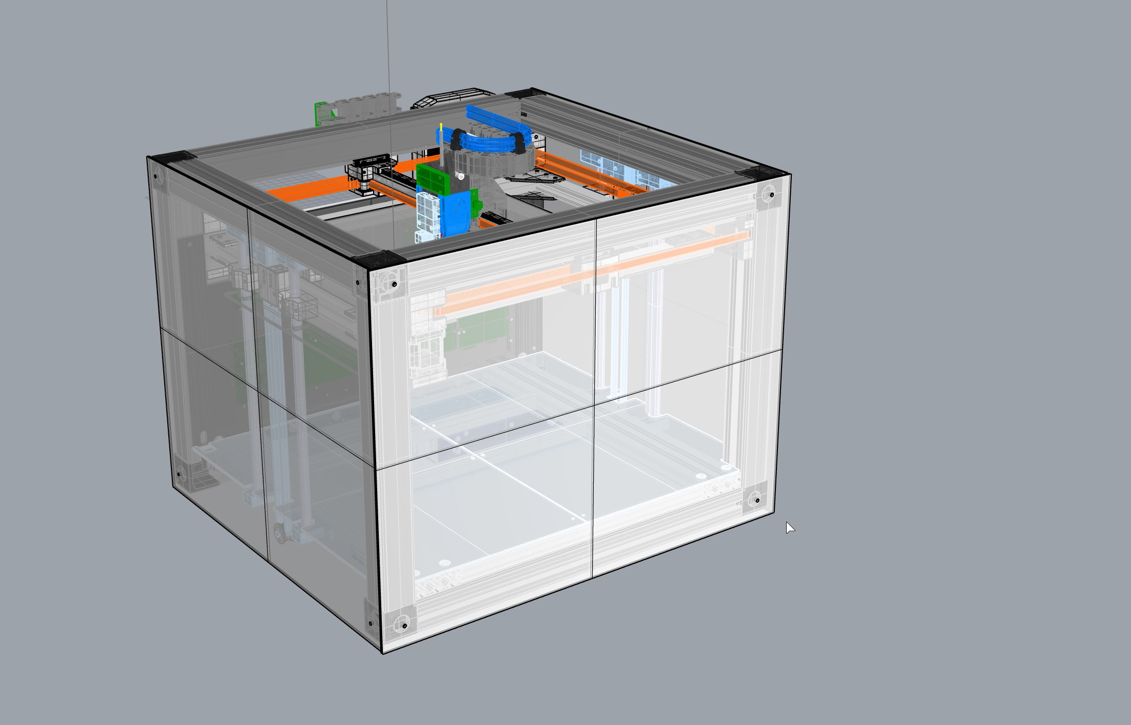
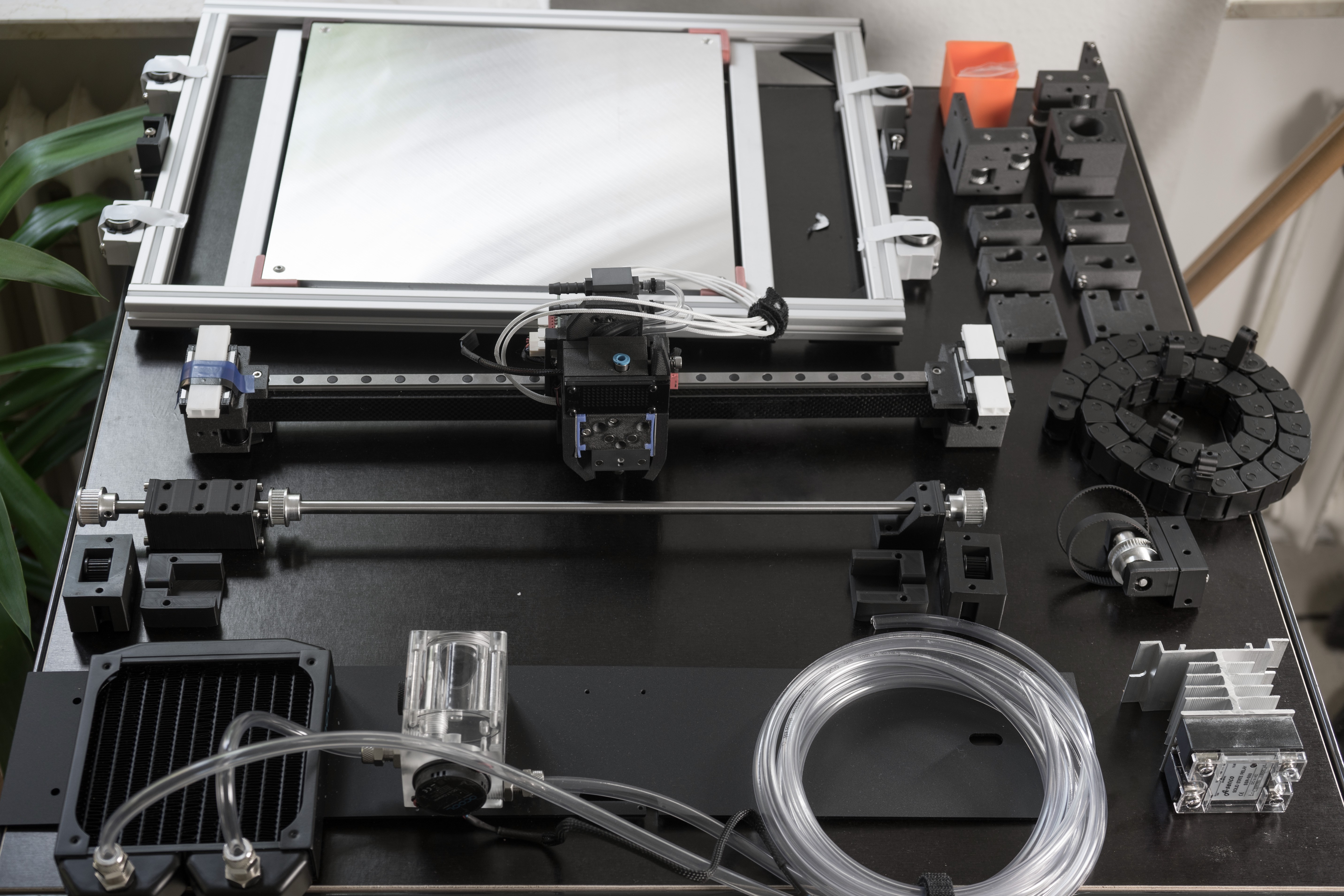
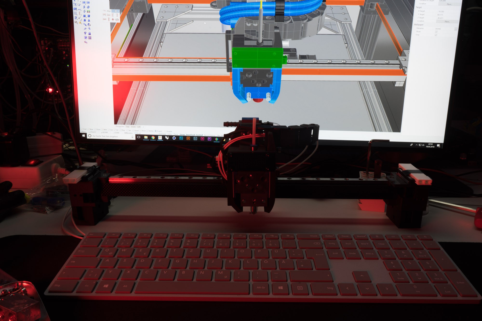
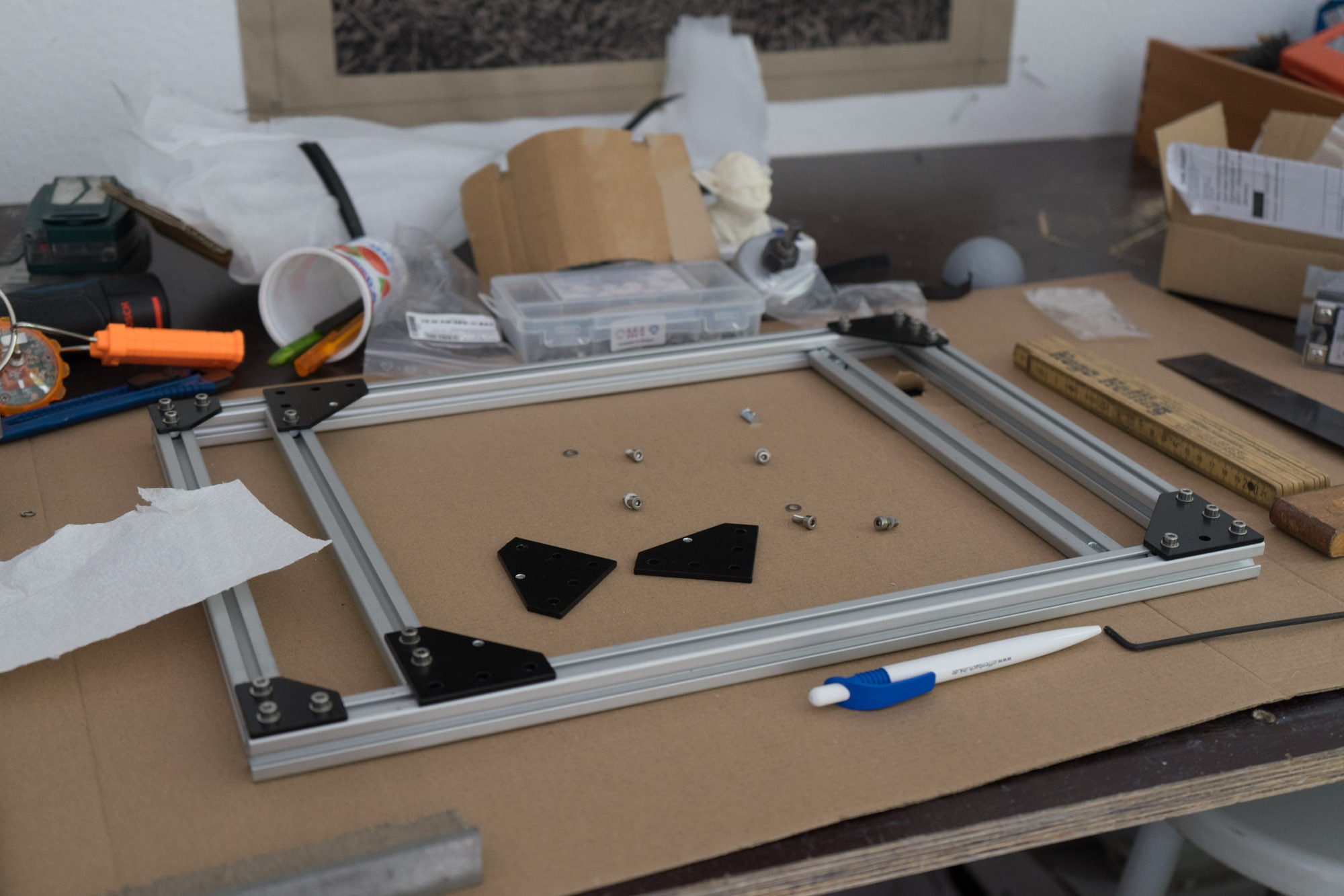
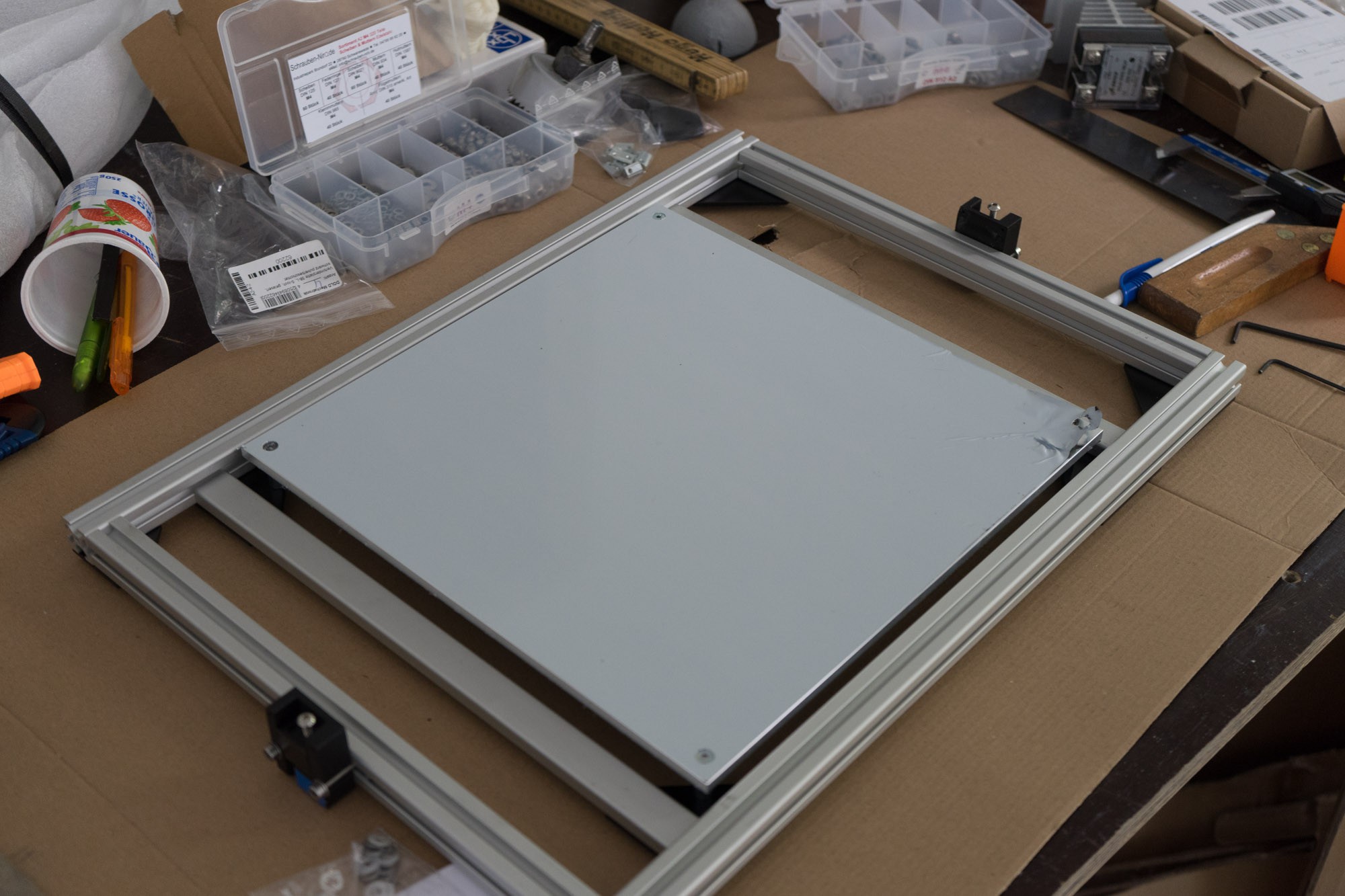
40x40 t-slot profiles form the 470x500x550mm (HxWxD) sized frame. The large build volume of 300x300mm can be used with up to five Materials. This is achieved by water-cooled exchangeable tool heads. The tools do not have their own cooling, instead they are cooled passively by the tool bank or the x-axis. While the tools are bowden driven the X-Axis carries one direct driven Extruder for flexible materials. The Z-Axis is based on belts with a 1:10 pulley reduction, compared to ball screws a fast, precise and cheap alternative. To keep the print area warm and chill im using 3mm laser cut acrylic sheets. All Axis are based on linear rails, the Y-Rail is supported by the T-Slot frame while the X-Axis is supported by a lightweight carbon square rod.
Features
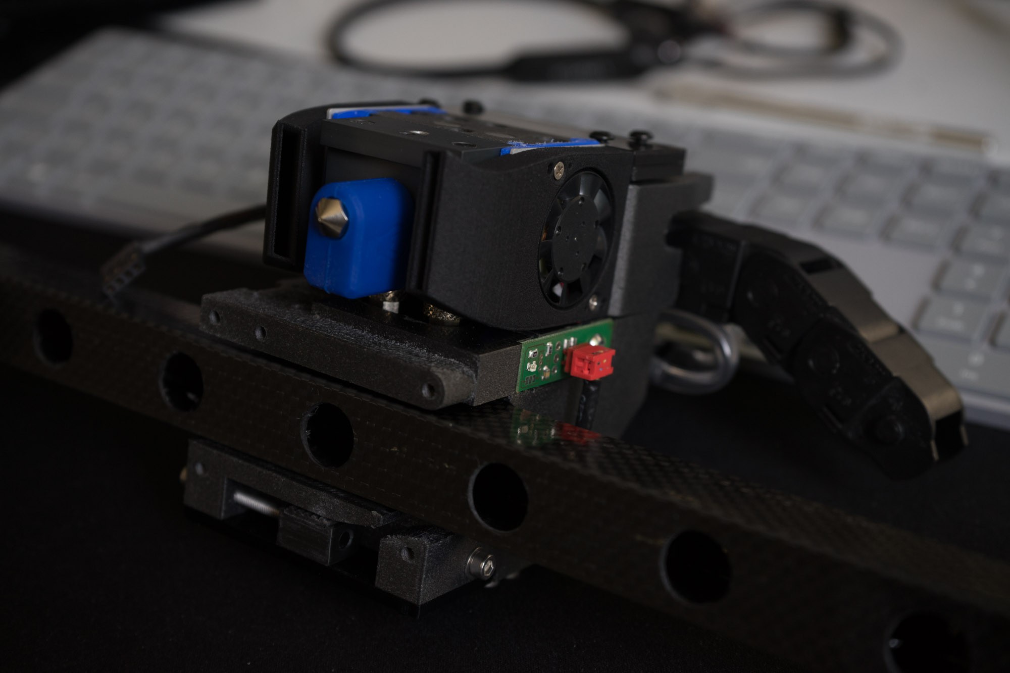
Watercooled Toolchanger
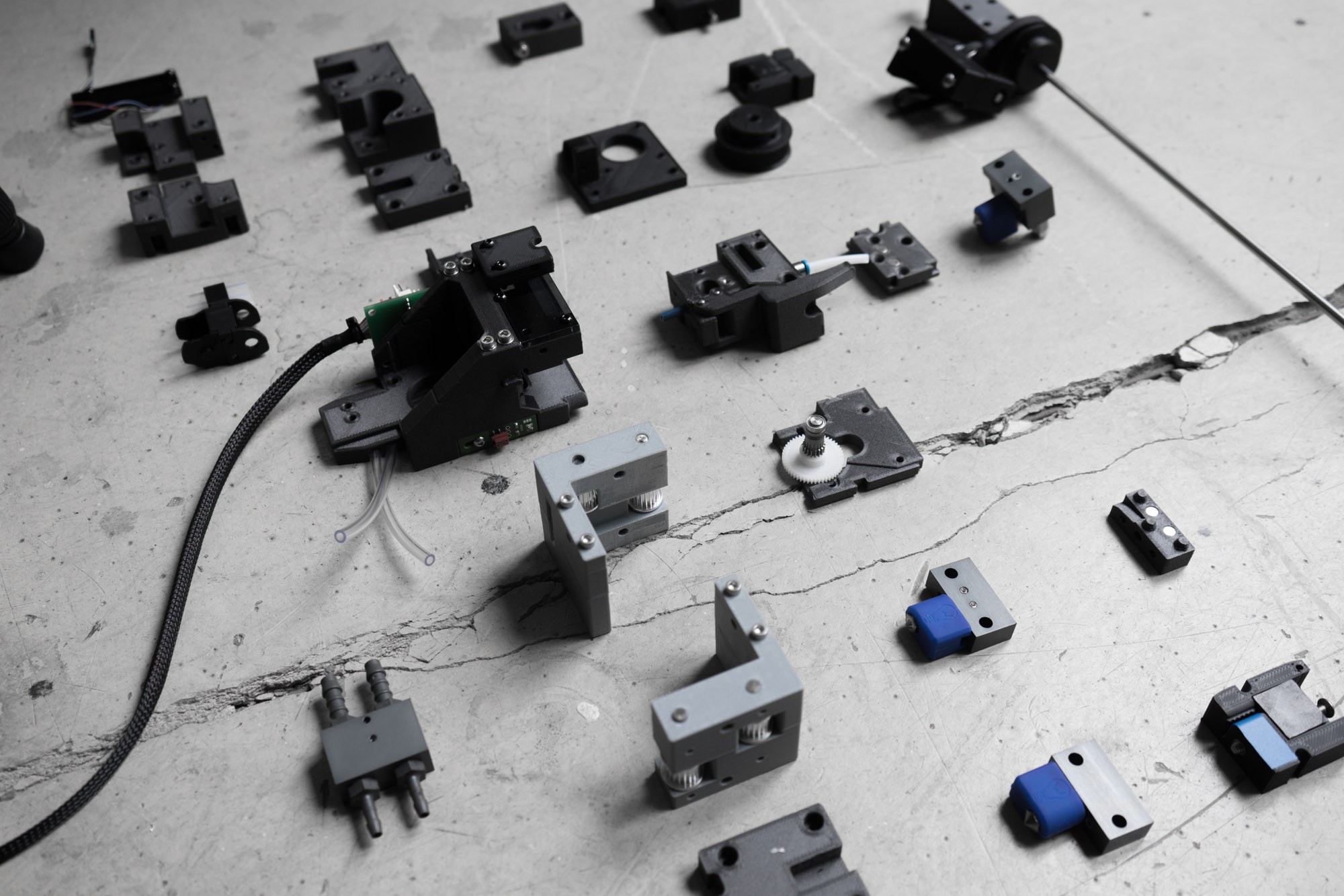
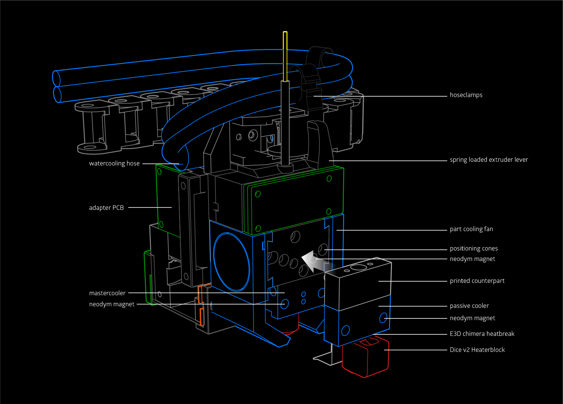
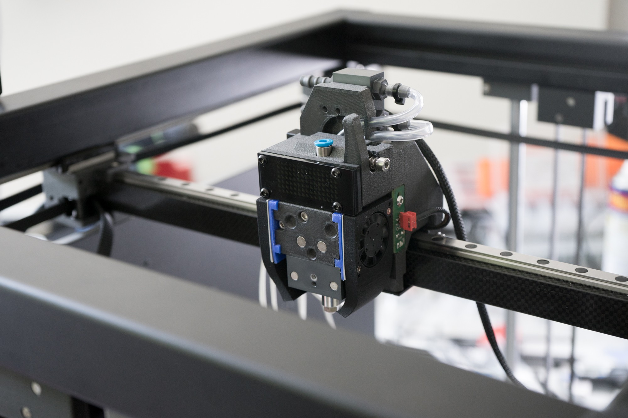
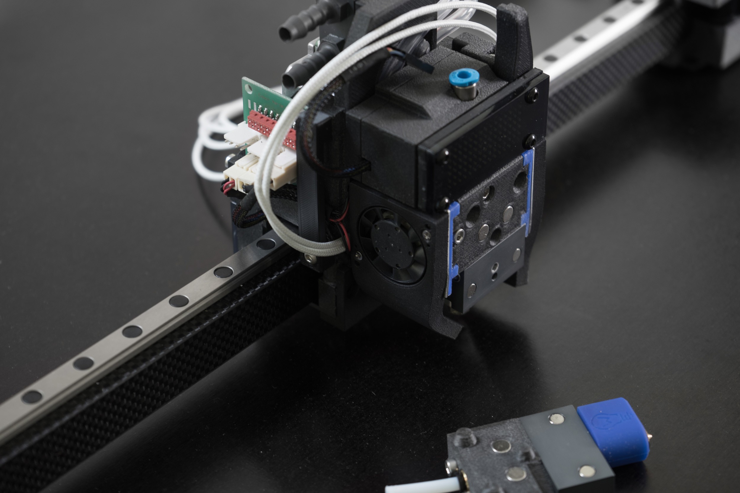
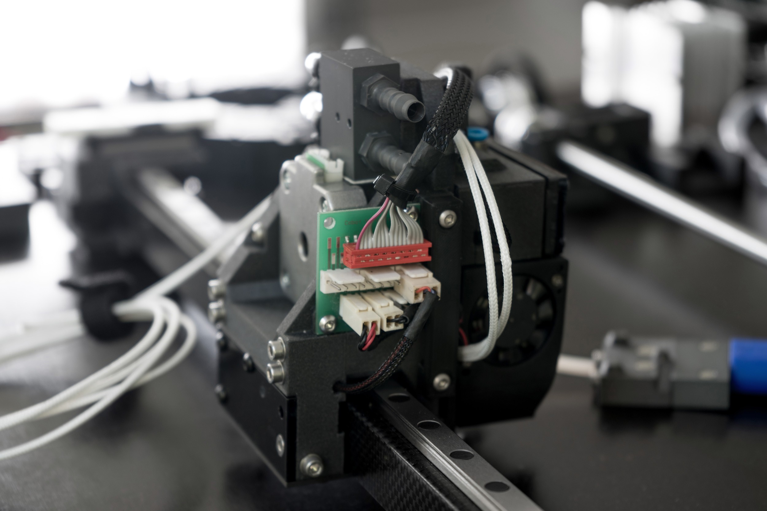
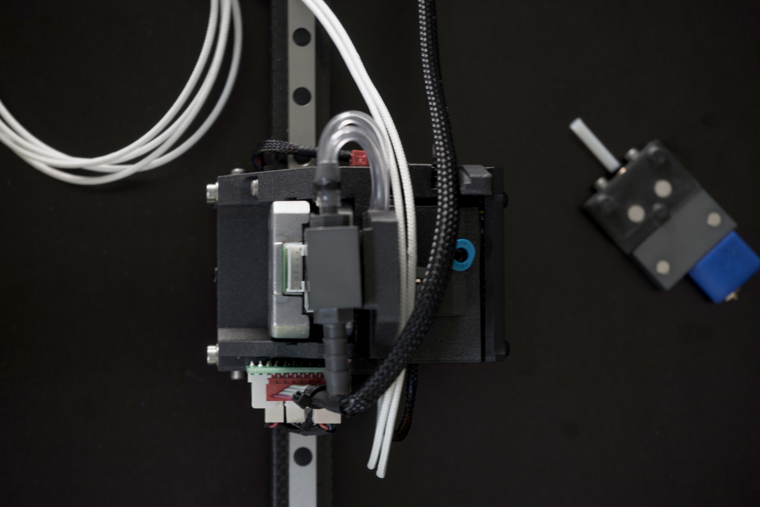
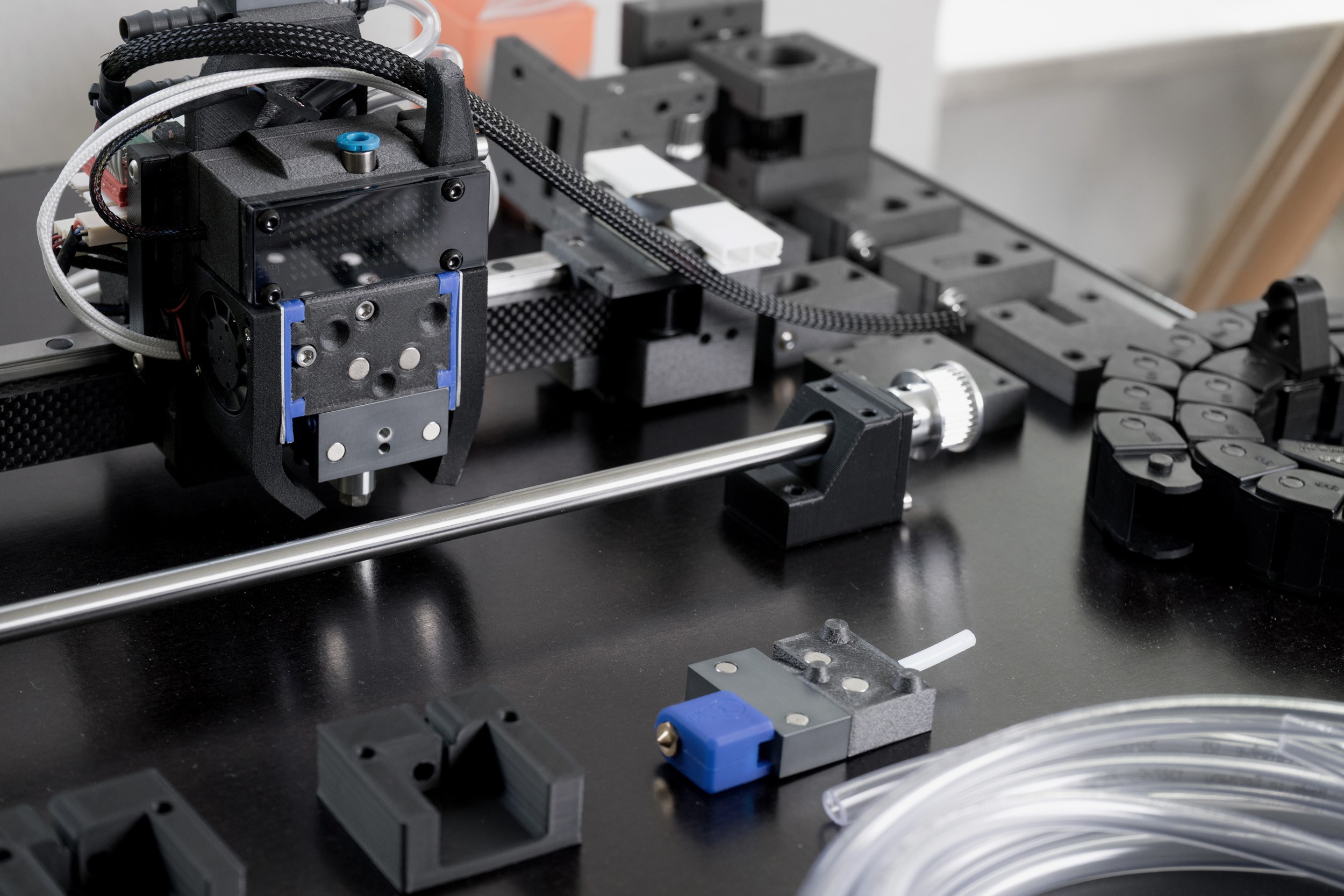
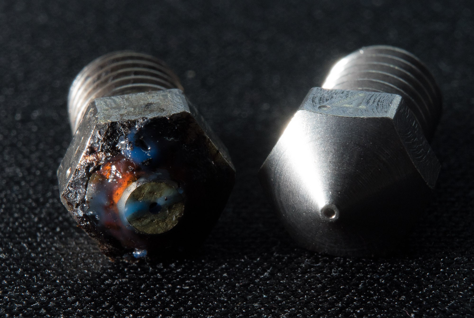
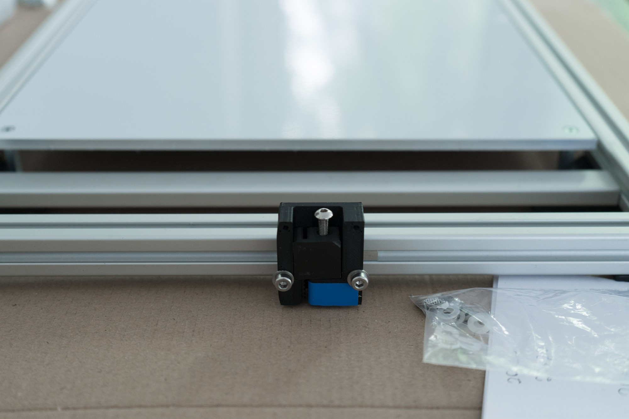
At first I build the Blackbox around a water cooled Kraken hot end with four extruders from E3D. But the results where a bit disappointing. My goal was and still is to be able to print complex composite parts with multiple materials. But the leakage of the inactive extruder made it really messy. I was aware of dual x-carriages and tool changing printer but i had no idea how to combine that with a water cooled hot end. Just to think about connecting several tools with their own cooling circle gave me nightmares. But one day it hit me, the tool can be cooled passive by a cooling cycle hooked to the extruder and the tool bank just by touching the cooled surface. The idea is that the tools are cooled on the tool bank while they are inactive and on the X-axis after they are picked up by it. As a result, the tools require neither cooling hoses nor fans and are therefore extremely compact and lightweight (<40g).
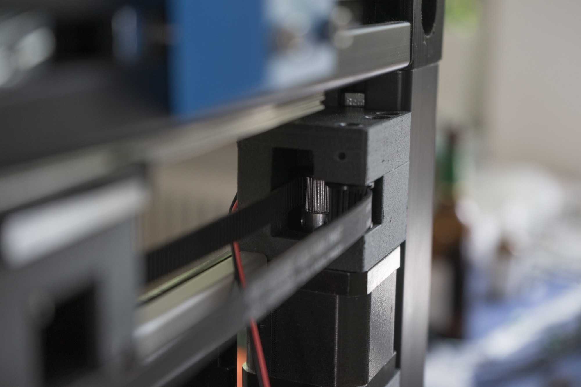
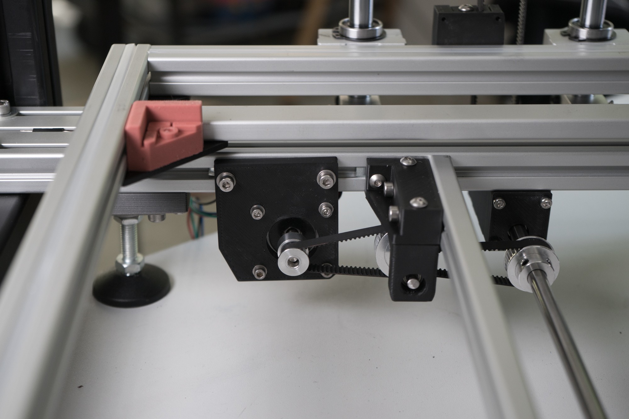
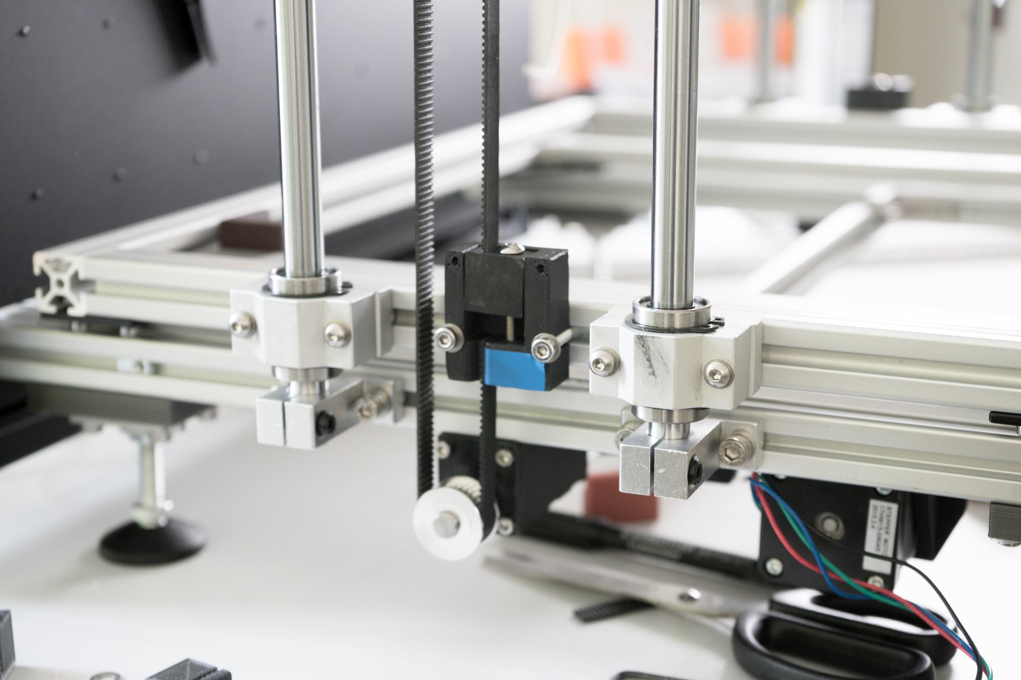
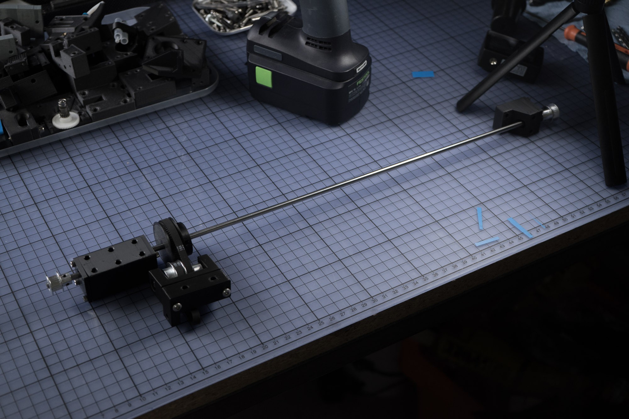
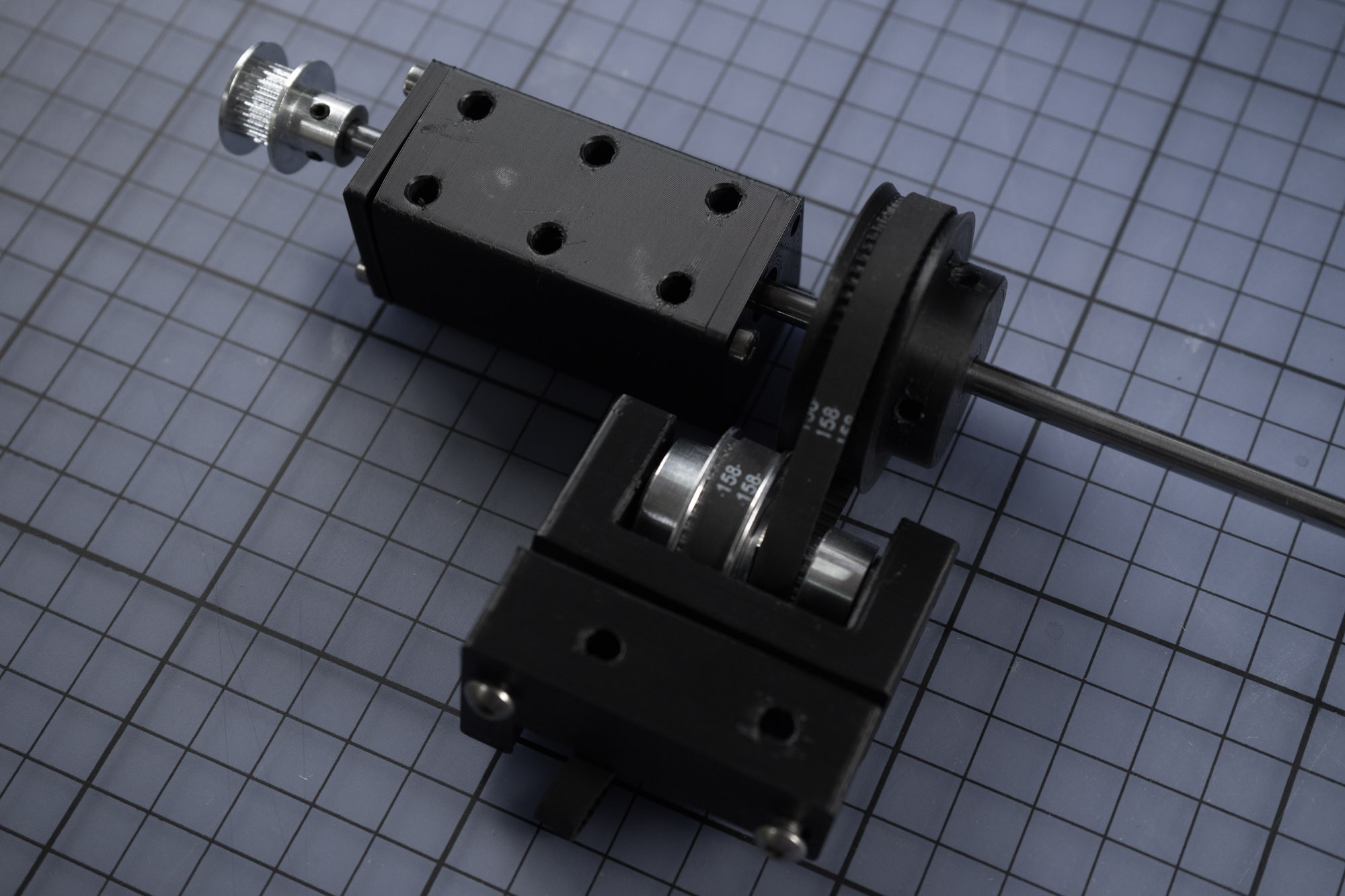
Belted zero backlash Z-Axis
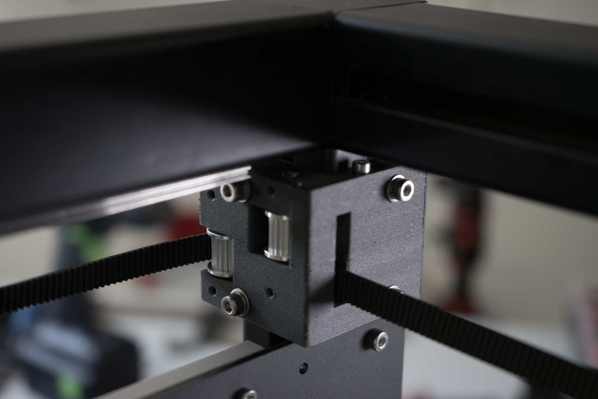
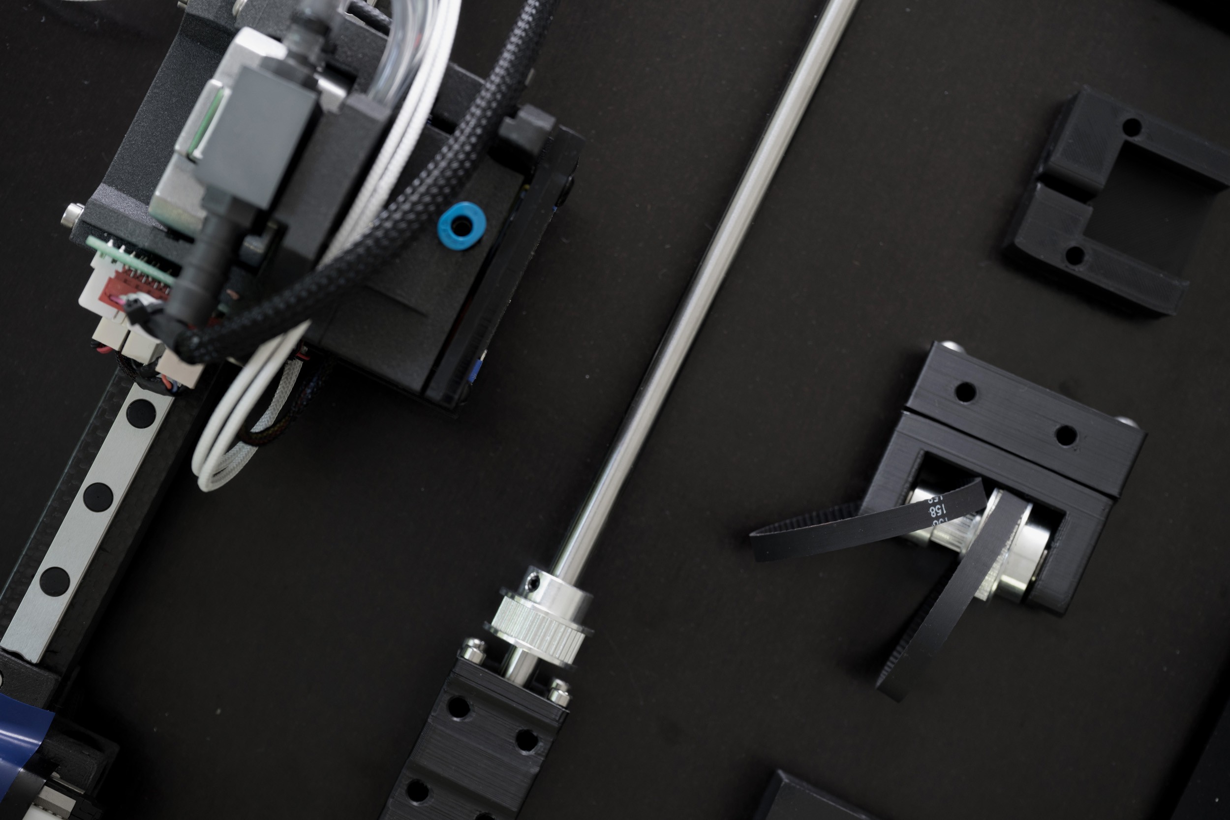
I started the Blackbox with a ball screw driven Z-Axis. It worked really precise with zero wobble, but it wasn´t able to accelerate fast because it was overconstrained. So I redesigned the Z-Axis completely based on belts. To achieve the necessary precision and to prevent the heating bed from falling down I use a 1:10 belt reduction. The Pulley configuration for the reduction is 16 teeth on 40 teeth, 16 teeth on 64 teeth. This results in a full step resolution of 0.01mm with 0.9° Stepper and almost no backlash, great for fast z-hop moves.

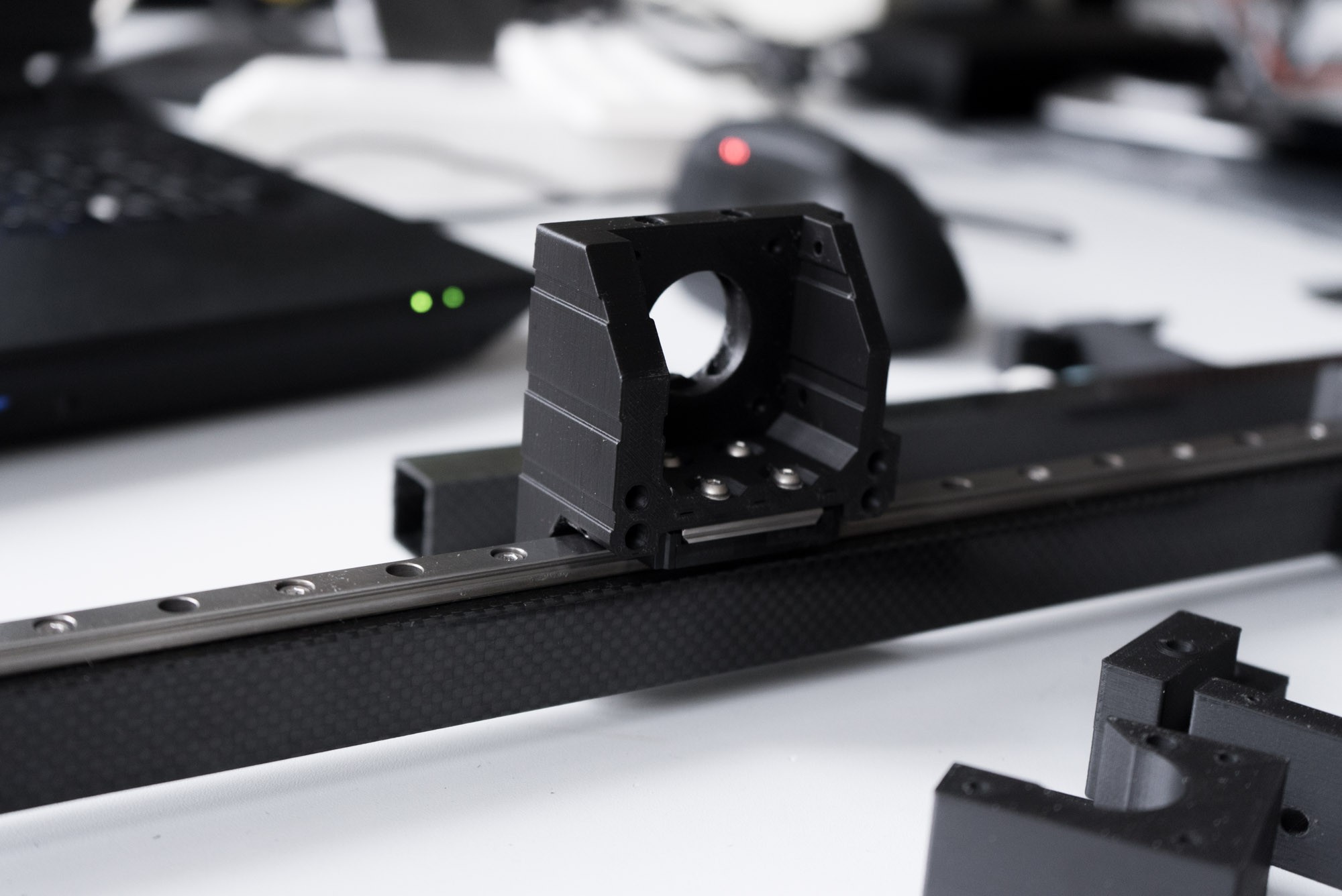
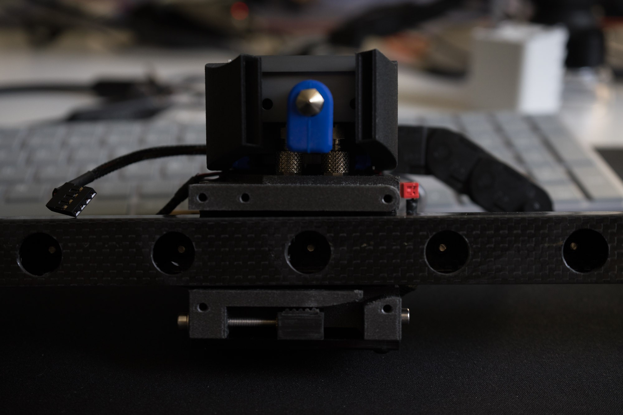
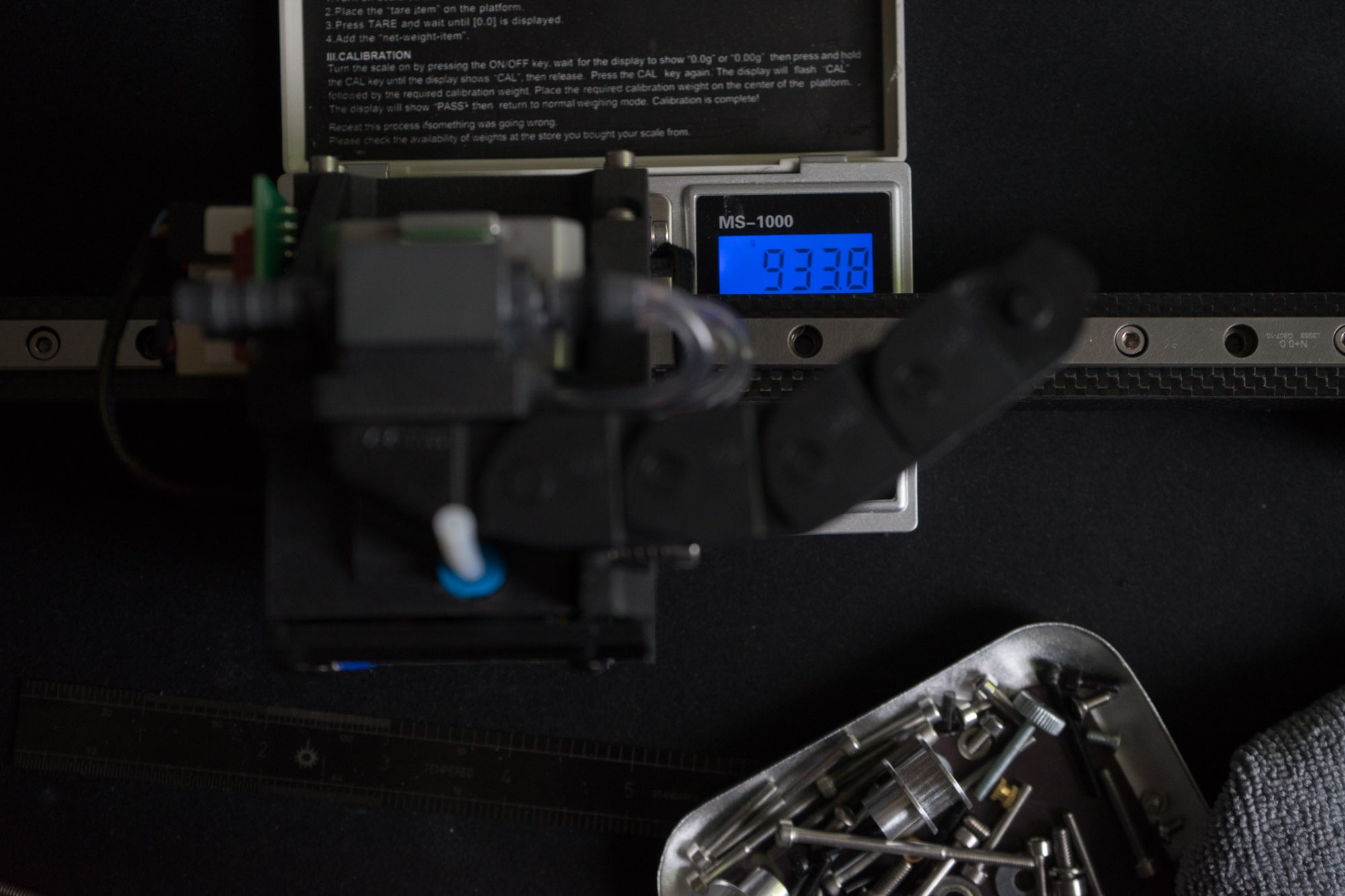
Carbon X-Axis
The X-axis is based on a small and lightweight MR9 (like MGN9) linear rail supported by a cheap carbon square tube. Im using printed brackets to guide the belts. Therefore the total x-axis including direct drive extruder and Y bearing weighs just about 750g-900g. This should reduce jittering and vibrations resulting in higher acceleration.
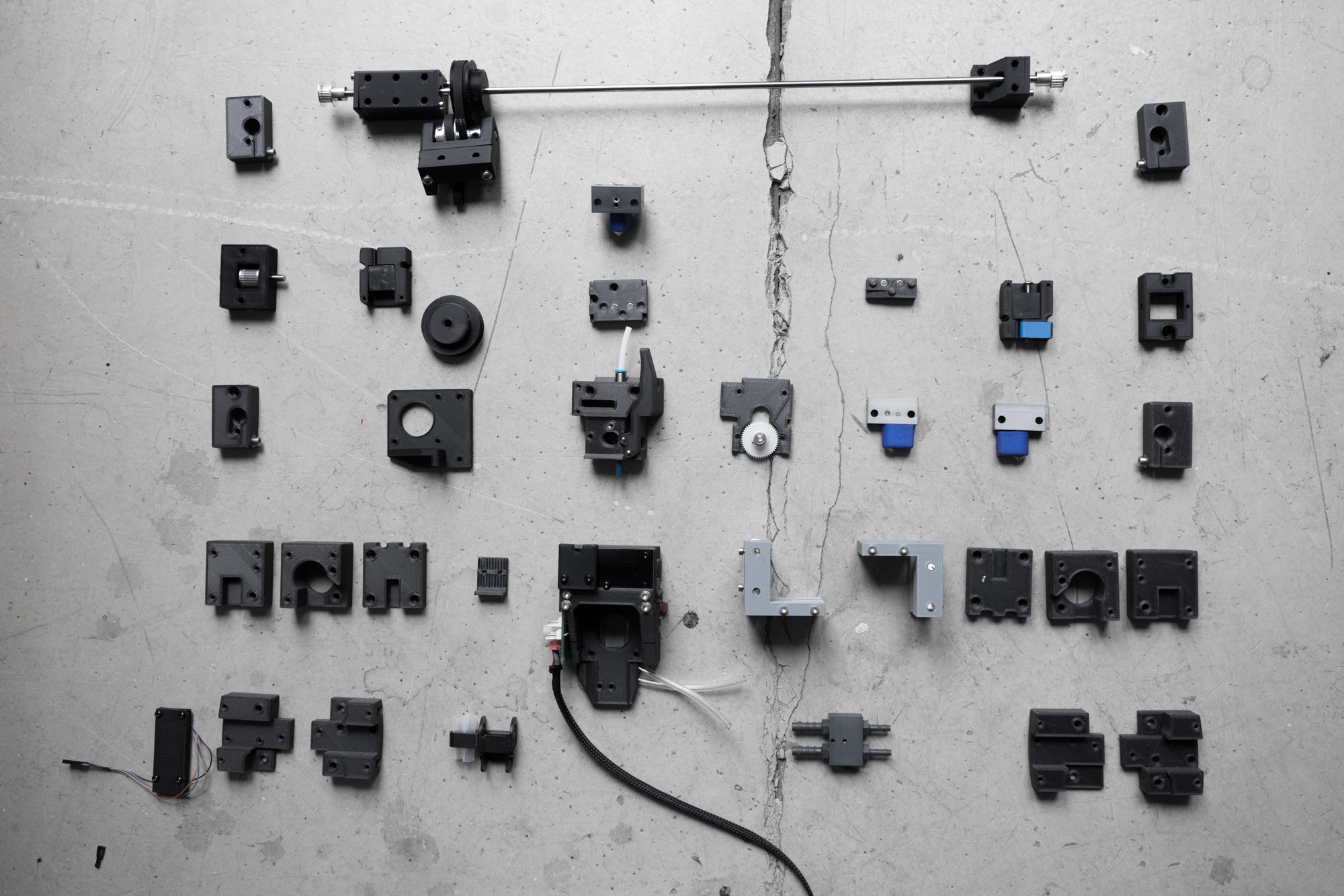
Accessibility
The black box was designed from the ground up with the idea of easy maintainability and assembling in mind. One example is the housing which can be completely removed within a few seconds. Another example is the X-Axis/Extruder which consists of very few parts and can be accessed easily. I also integrated cable channels which should clean up the wiring. All bearings are clamped in a way they can´t pop out. This is the result of extended iteration and prototyping. Im working almost two years...
Read more »


 jurc192
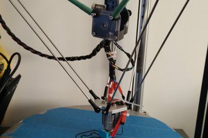
 Aaron Dominic Richmond
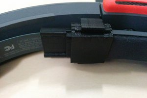
 Ryan
Ryan
 J. Kha
Hello again,
The more I discover, the more I adore!
My project would rather be on a volume: 1300x900x500 mm in the context of applications that I have to do.
Do you think I can just extrapolate the lengths, or as I think the frame will not be strong enough?
===========================================
Re-Bonjour,
Plus je découvre, plus j'adore !
Mon projet serait plutôt sur un volume : 1300x900x500 mm dans le cadre d'applications que j'ai a faire.
Pensez vous que je peux juste extrapoler les longeurs, ou comme je le pense, le chassis ne sera pas suffisament solide ?