 Wenting Zhang
This is a project update about the hardware side of the VerilogBoy Handheld.
After testing the previous prototype (Rev 0.1), I feel like several changes are required:
- Add a dedicated DPI-to-DSI bridge chip. My poor implementation of the D-PHY transcevier simply couldn't meet the signal integrity requirement. This is an experimental change to test how much it can improve without doing major change to the board (for example, moving to 6-layer, adding decoupling capacitors that would interfere with overall structure, etc.).
- Replace the Micro-Type-B USB socket with Type-C socket. No Alt Fn or PD support is planned, just working under USB 2.0 FS slave (sink) mode.
- Add a microcontroller to handle hardware initialization, RTC, and USB FS communication (for example, flashing new firmware to the on-board SPI flash.
- Fix various incorrect component footprint.
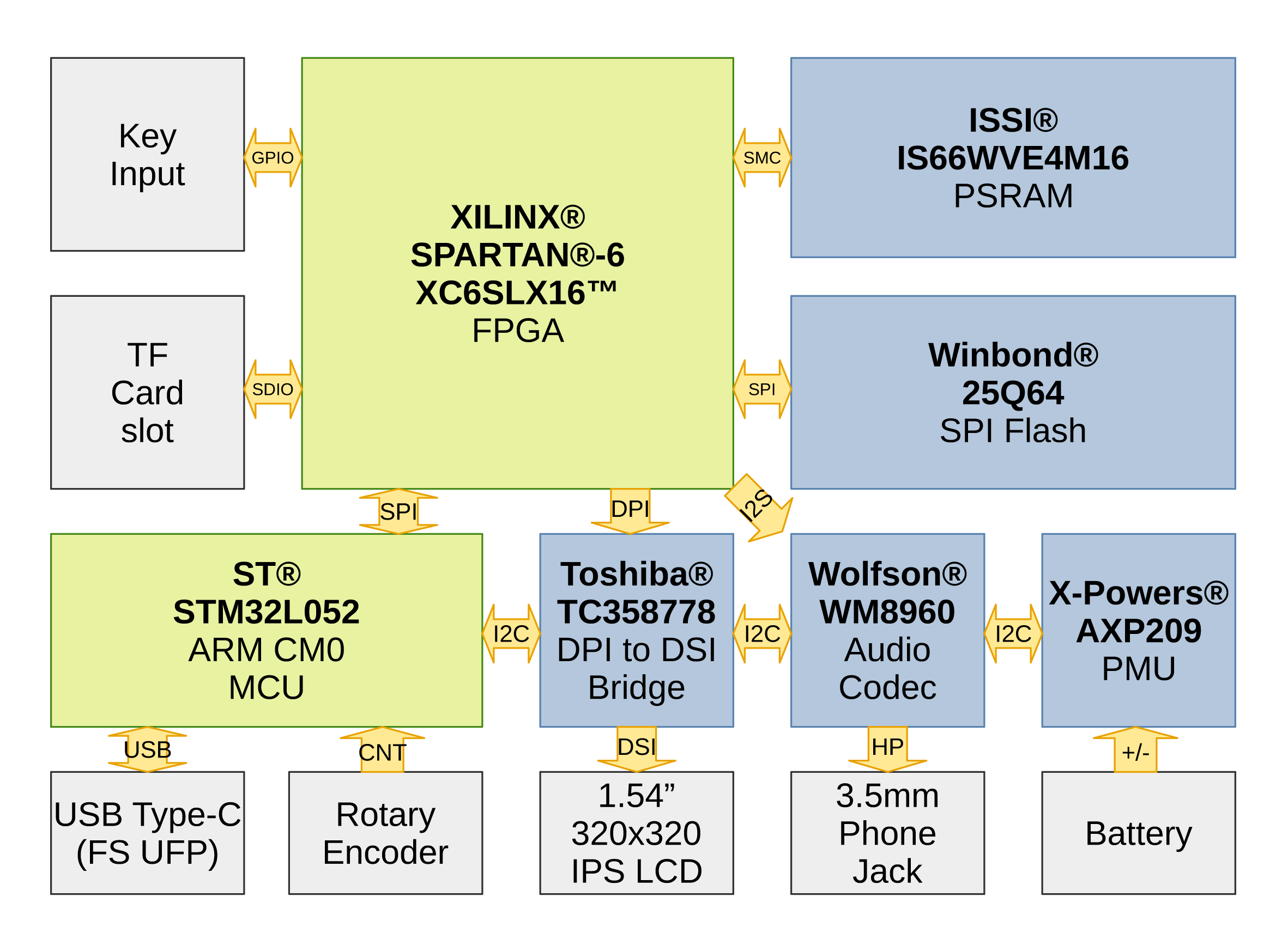
Here shows a revised hardware architecture. This is probably overly complicated for a hobby project.
Due to the closure of PCB manufacturers because of the Chinese New Year, we are probably not going to see the new prototype (Rev 0.2) in the Feburary. I will continue working on the HDL side of the prototype and trying to finish the CPU refactoring within the coming weeks.
For the time being, thanks for reading.
Discussions
Become a Hackaday.io Member
Create an account to leave a comment. Already have an account? Log In.
Looking good, but does the power chip connect to the audio chip?
Are you sure? yes | no
yes, they are just on the same bus, so they are “connected”
Are you sure? yes | no
Ahh, interesting. Thanks
Are you sure? yes | no