 Kumar, Abhishek
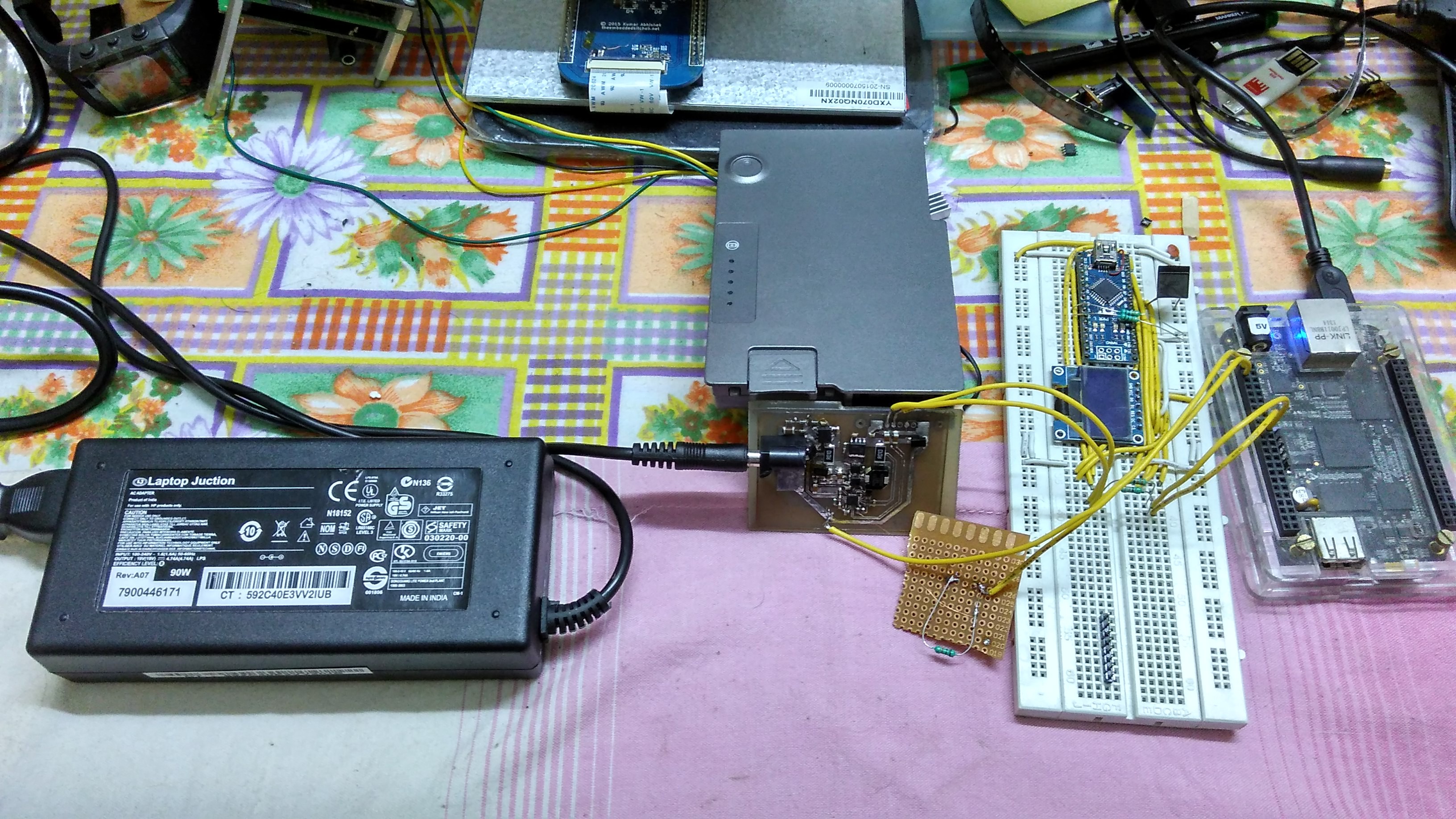
The project aims to build a power pack solution that
- Charges fast / allows devices to charge even while charging itself
- Provide consistent charging to devices connected to it
- Be as energy efficient as possible
- Provide Consistent information about its own state (hours charge remaining etc)
- Power small computers like the Pi, the BeagleBone Black reliably for long periods like an online UPS
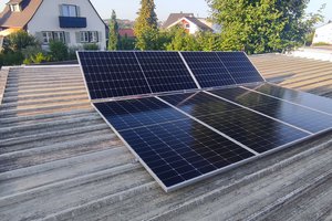
- [In the long term] Provide support for renewable energy harvesting using solar cells / MPPT with firmware upgrades.
I see this project move towards a standard for powering almost any portable gadget, and can be expanded in the future to support LED lighting and BLDC fans to create a completely DC-powered room run by a battery pack.
Licenses
Firmware will be licensed under MIT License.
Hardware under a CERN Open Hardware License.
This project makes use of the Smart Battery Specification given at http://sbs-forum.org/specs/sbdat110.pdf which is copyrighted by the Smart Battery Implementers Forum.


 Dominic Buchstaller
 ric866
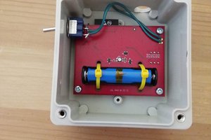
 deʃhipu
wont that battery power affect your phone in any way