 Dhawal Patel
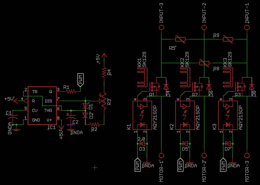
Simple circuit contains a 555 Timer in astable mode. The pulse width of oscillation will be controlled by pot. The output frequency will be around 10KHz. The output of 555 timer will be passed to gate driver. As the source of mosfet will be floating between 650V to -650 V it requires an isolated gate driver.
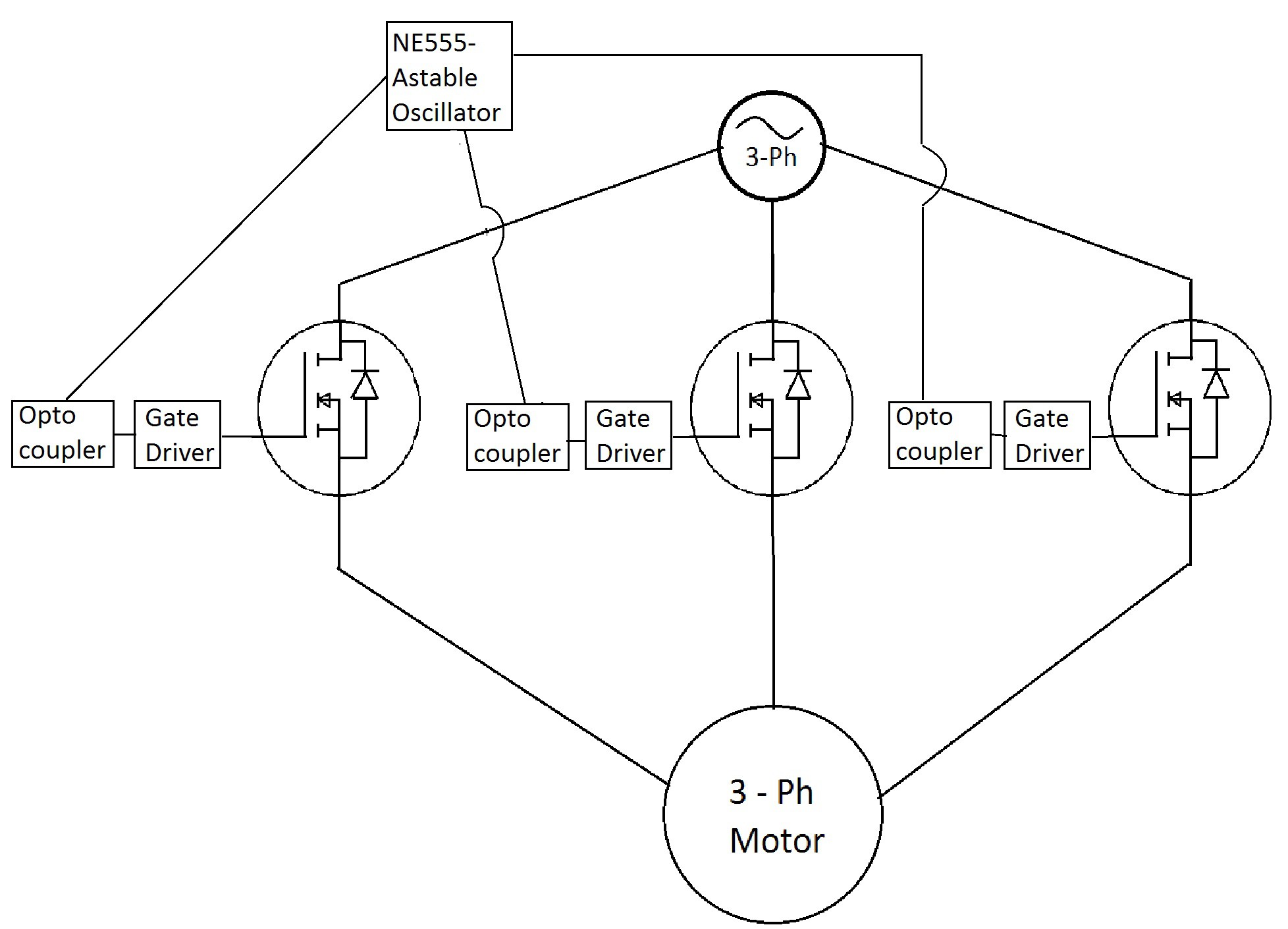
There is one mosfet per phase. Mosfet will be switched irrespective of AC half. During positive half the mosfet will be in forward mode and will switch input, thus modulating the voltage. While in reverse mode the reverse recovery diode will allow full wave to pass.
As in 3-Phase AC at least one phase will be in -Ve half. So when two mosfet in +Ve are modulating the 3rd mosfet will be sinking all the current that is passing through the motor. Thus inter-phase voltage is modulated.
Here is a block diagram for the project.
 Mrinnovative
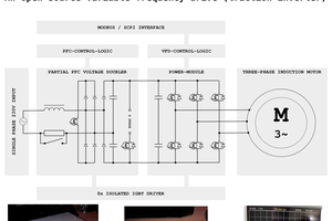
 DANTRACX
 ElectronicABC
sorry its for a primary 3phase welder