 Rui Rex
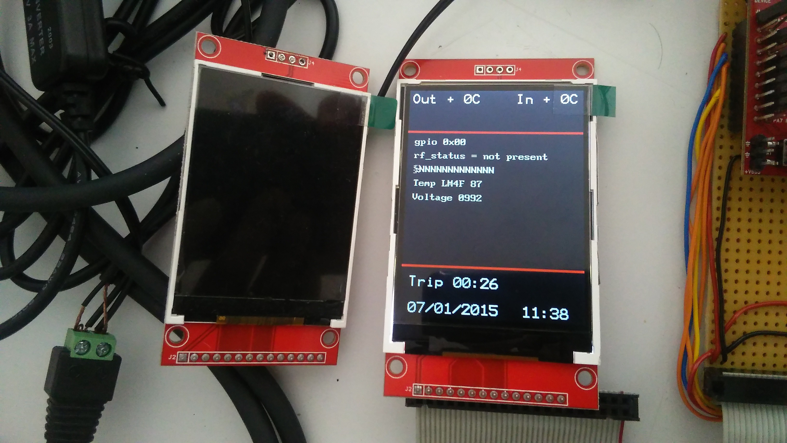
The Stellaris board will be the responsible for controlling the display, read the temperatures from the internal and the external sensors, reading the cluster alarms (via I/O expander) like fuel warning, coolant temperature, oil level and brake problems, and user interface buttons.
Latter it will be possible to read OBD diagnostics either by direct UART connection or via Bluetooth to the OBD-Bluetooth adapter.


 Chris Combs
 deʃhipu
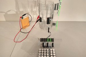
 matseng
 Morning.Star
Project dead or still in progress?