Close
0%
0%

Delta-Sigma versus PWM

Delta-Sigma: solution for a virtually unlimited number of DACs, and with faster refresh rates than PWM. Applicable on any microcontroller.

Similar projects worth following
The number of hardware PWM channels is usually limited. The alternative, software PWMs, leads to slow refresh rates and low precision for the PWM duty cycle. Delta-Sigma is much better then PWM, in both the duty cycle accuracy and the number of instructions.

This is a demonstration of 10 LEDs intensity modulators (as many as the MCU's available pins) running on a MSP430G2211 without flickering.

Sigma-Delta modulation algorithm is implemented using "synthetic division", and is calculated in just 5 clock cycles (5 instructions) per each LED.

The project was inspired by a Jason Sachs's article (link inside code). Thanks Jason!

The code that calculates the Sigma-Delta "synthetic division" is made of just these 5 lines:

// Sigma delta modulation algorithm using "synthetic division"
		sum[n] += req[n];		// Update integrator value
		if (sum[n] < max[n])
			outBits++;		// LSB = 1
		else
			sum[n] -= max[n];	// LSB = 0 (untached) and adjust integrator

The complete code can be found in the GitHub repository. The rest of the lines from file https://github.com/RoGeorge/Delta-Sigma_versus_PWM/blob/master/main.c is just waving the colors.

  • sum[n] is an accumulator, similar with the PWM counter
  • req[n] is the duty cycle, equivalent of the PWM compare register
  • max[n] is the overflow value for the accumulator
  • n is the channel number, in this demo there are 10 independent "PWM like" channels

Apart from the intimidating name, "synthetic division", the implementation is pretty simple:

At each step, add the requested duty cycle to an accumulator. When the accumulator overflows, you set the output to high. If it doesn't overflow, you reset the output to low. Then, in the next step, continue adding from where you were left.

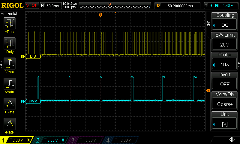
The maximum advantage regarding the refresh rate is at 50% duty cycle, where Delta-Sigma becomes 'max/2' times higher then PWM, where 'max' is the overflow value.

As an example, for an 8 bits PWM at 50% duty cycle, Delta-Sigma has a refresh rate 128 times higher then a PWM. For a 16 bits PWM, the Delta-Sigma would be 32768 times better at refresh rate.

One more advantage is that Delta-Sigma is more responsive. You can modify the duty factor on the fly, without waiting for the whole cycle to end. Of course, you can also choose a different resolution for each channel by modifying max[n].

3D Printing AVR Arduino Art Audio Automation BeagleBone Bluetooth Cameras Clock Drones Environment Hardware IoT LED Medical Music Radio Raspberry Pi Remote Control Robotics Rockets Satellites Science Security Software Virtual Reality Wearables

  • 1 × MSP430G2211 Microprocessors, Microcontrollers, DSPs / ARM, RISC-Based Microcontrollers
  • 2 × RGB LED 3 LEDs (Red, Green, Blue) in the same case, common anode
  • 2 × RG LED 2 LEDs (Red, Green) in the same case, common cathode
  • 8 × 100 Ohms Resistor
  • 2 × 33 Ohms Resistor

View all 6 components

  • Delta-Sigma vs PWM: Waveforms

    RoGeorge06/28/2015 at 00:22 1 comment

    The yellow channel is Delta-Sigma, blue channel is PWM.


    While PWM keeps it's frequency constant when increasing the duty cycle, Delta-Sigma increase the number of it's pulses and keeps the wide of each pulse constant.

    This is how Delta-Sigma is avoiding flickering much better then PWM, but with the same computational effort.

    Next is an animated picture at different duty factors, for the same computational effort.
    At 50% duty cycle, Delta-Sigma have a maximum refresh rate of 1250 Hz, while PWM have only 10 Hz.

    3D Printing AVR Arduino Art Audio Automation BeagleBone Bluetooth Cameras Clock Drones Environment Hardware IoT LED Medical Music Radio Raspberry Pi Remote Control Robotics Rockets Satellites Science Security Software Virtual Reality Wearables

  • GitHub sources added for CCS 6.1.0

    RoGeorge06/24/2015 at 07:57 0 comments

    GitHub repository with all the sources for CCS 6.1.0: https://github.com/RoGeorge/Delta-Sigma_versus_PWM

    3D Printing AVR Arduino Art Audio Automation BeagleBone Bluetooth Cameras Clock Drones Environment Hardware IoT LED Medical Music Radio Raspberry Pi Remote Control Robotics Rockets Satellites Science Security Software Virtual Reality Wearables

  • PWM, DAC, MCU, RGB, RG, LED, MSP, WDT?

    RoGeorge06/18/2015 at 19:03 0 comments

    PWM = Pulse-Width Modulation
    DAC = Digital-to-Analog Converter

    A PWM followed by an integrator is turning into a DAC, in order to control the intensity and the color of the LEDs.

    MCU = MicroController Unit
    RGB = Red, Green, Blue
    RG = Red, Green
    LED = Light-Emitting Diode
    MSP = Mixed Signal Processor
    WDT = WatchDog Timer
    GCC = GNU Compiler Collection
    GNU = GNU is a recursive acronym for "GNU's Not Unix!" (Wikipedia)
    CCS = Code Composer Studio (an IDE tool from TI)
    IDE = Integrated Development Environment
    TI = Texas Instruments

    3D Printing AVR Arduino Art Audio Automation BeagleBone Bluetooth Cameras Clock Drones Environment Hardware IoT LED Medical Music Radio Raspberry Pi Remote Control Robotics Rockets Satellites Science Security Software Virtual Reality Wearables

  • Why MSP430?

    RoGeorge06/18/2015 at 18:53 0 comments

    It just happened to have one MSP430G2211 lying around. It came together with a Texas Instruments MSP430 LaunchPad, as a spare second microcontroller.

    3D Printing AVR Arduino Art Audio Automation BeagleBone Bluetooth Cameras Clock Drones Environment Hardware IoT LED Medical Music Radio Raspberry Pi Remote Control Robotics Rockets Satellites Science Security Software Virtual Reality Wearables

  • Why not PWM?

    RoGeorge06/18/2015 at 18:49 0 comments

    Because in PWM, for each PWM period, there is only one big pulse, wider or thinner according with the duty cycle.

    On the countrary, in Delta-Sigma there are many thinner pulses corresponding to the same PWM period, and spatially spread over the whole period. The bigger the duty cycle, the bigger the number of the thinner pulses per each period.

    3D Printing AVR Arduino Art Audio Automation BeagleBone Bluetooth Cameras Clock Drones Environment Hardware IoT LED Medical Music Radio Raspberry Pi Remote Control Robotics Rockets Satellites Science Security Software Virtual Reality Wearables

View all 5 project logs

Enjoy this project?

Share

Discussions

nicoud jean-daniel wrote 12/07/2016 at 12:30 point

The name is also PFM (pulse frequency modulation), and you see it mentioned in DC-DC converters, that switch for PFM when power is low. I promote PFM for motor control for years

http://www.didel.com/kidules/PwmPfm.pdf Its in French, but you will understand the pictures.

Well, it's decided. See http://www.didel.com/PFMversusPWMforRobots.pdf  after Dec 12, 2016. Soft will be on Github.

  Are you sure? yes | no

James Newton wrote 12/22/2015 at 16:27 point

I was trying to understand how outBits got cleared between cycles... but of course it's because the old value is shifted out. In the code, the comment says "rotate" but <<= does a shift not a rotate. LOL... the comment infected me and I thought the bit from the left would be rotated back to the right. The human mind is silly. This is excellent code. Thank you!

  Are you sure? yes | no

RoGeorge wrote 08/13/2016 at 06:59 point

Good catch! Sorry about the misleading comment.

Thank you & fixed.
:o)

  Are you sure? yes | no

Rainharvester wrote 07/07/2015 at 01:49 point

this sounds like Breshingham's algorithm.  Used in graphics to draw lines.  I was working on a similar code to optimize pwm (so 1/2 cycle pwm does 101010101010 instead of  000000000111111111.

  Are you sure? yes | no

RoGeorge wrote 07/07/2015 at 06:53 point

Interesting. I will look into Bresenham's line algorithm, thanks!

  Are you sure? yes | no

Rainharvester wrote 07/07/2015 at 11:42 point

When I did mine, I had very little cycles to do anything else.  Is this the case for you too?  I guess it doesn't cost too much to dedicate a 2211 as a dac.  It's one of the cheapest options I think.

  Are you sure? yes | no

M1k3y wrote 06/23/2015 at 16:52 point

Although I don't know exactly how the delta-sigma method works, I can say that you can go faster with software PWM. I did write some code for an Atmega8 that uses 4 instructions per pwm cycle and LED to calculate wether the LED should be on or not. The IOs were multiplexed with some simple shift-registers and in the end I was able to drive 64 LEDs with 8 bit per LED und 220 Hz on the Atmega8 running on 8MHz internal clock.

I will try to find the Code I used back than.

  Are you sure? yes | no

[deleted]

[this comment has been deleted]

RoGeorge wrote 06/23/2015 at 16:48 point

Well done!

How did you manage to run 64 LEDs x 8 btis x 220 Hz x 4 instructions = 14 417 920 instructions / second with a clock of 8 MHz? Were the 64 LEDs independently controllable?

  Are you sure? yes | no

M1k3y wrote 06/23/2015 at 16:53 point

>14 417 920
Shame on me, I mixed some numbers up.The Code ran only with 32, and could be expanded to 64 LEDs when using external oscillator. Its been quite some time since I did this, I hope I can be forgiven.

And yes, the LEDs were controlled independently

  Are you sure? yes | no

RoGeorge wrote 06/24/2015 at 08:10 point

Don't worry.
I'll try to put in the project a comparison picture between the waveform of a Delta-Sigma and a PWM. This will show the advantages of Delta-Sigma, especially on the refresh rate.

  Are you sure? yes | no

Eric Hertz wrote 06/24/2015 at 10:35 point

This is a handy technique... I was unaware of this name for it, nor the term "synthetic division". Thanks for those :)

There's a decent explanation on wikipedia, albiet a bit theory/math-intensive for my taste.

An explanation of a benefit could be e.g. the example given on the wikipedia entry for "Delta-Sigma Modulation" (or "Pulse-Density Modulation"?)... which compares to PWM: 

Imagine a 50% duty-cycle PWM signal which has a period of 256: in PWM the output will be active for 128 counts, followed by 128 counts of inactivity. Whereas, with this the DSM/PDM output would toggle between one count active, and one count inactive. So, the effective period is 2, rather than 256 (much higher-frequency, assuming the same clock-source/cycle-count).

A couple other thoughts:

If implemented as such, you can get fractional-powers that aren't available in a fixed-period PWM case... e.g. 3/7ths power output, which in the PWM case would have to be converted to a close fraction of n/256.

Also, this same technique can be used for other things, entirely, such as e.g. drawing a diagonal line across a screen, or stretching pixels across an arbitrary width, without using repetitive/long floating-point calculations or division...

(can you tell I've done a tiny bit with it? I called it "high-frequency modulation"/hfModulation, before I knew it had a name... ;)

Nice demo/details, btw!

  Are you sure? yes | no

RoGeorge wrote 06/28/2015 at 01:09 point

Thanks! The term "synthetic division" was a surprise for me too, and
Google doesn't pointed either to what I was expecting to see, but since
the author used that term together with a nice tale, it was too nice to
not mention it.

Apart from the intimidating name, the implementation is pretty simple:
At
each clock, add the requested duty cycle to an accumulator. When the
accumulator overflow, you pulse the output for one clock.
Indeed, the maximum advantage regarding the refresh rate is at 50% duty cycle, where Delta-Sigma becomes n/2 times higher then PWM, where n is the overflow value.

As an example, for an 8 bits PWM, Delta-Sigma has a refresh rate 128 times bigger then a PWM.
For a 16 bits PWM, this Delta-Sigma would be 32 000 times better at refresh rate.

  Are you sure? yes | no

Eric Hertz wrote 06/28/2015 at 09:23 point

Hah, actually, that was a pretty good read, thanks for that link and convincing me to follow it :)

Also, *really* good point regarding 16-bit PWM!

  Are you sure? yes | no

Similar Projects

Does this project spark your interest?

Become a member to follow this project and never miss any updates