Close
0%
0%

Crazyradio for Cheapskates

Turning a wireless mouse USB adapter into a quadcopter transmitter

Similar projects worth following
The Bitcraze Crazyflie 2.0 quadcopter can be controlled by a PC with the Crazyradio USB radio dongle. Unlike the first-gen Crazyflie, this isn't required since the 2.0 works out-of-the-box with Android or iOS as a controller over Bluetooth. However the Crazyradio opens up some fun features like servo absolute position control using Kinect or telemetry from hacked-on sensors. Bitcraze is kind enough to open source their products, giving source, tools, and documentation for the firmware running on the Crazyradio's nRF24LU1+ SoC.

It just so happens that the Logitech Unifying Receiver, a tiny dongle for wireless mice and keyboards, contains an nRF24LU1+.

Warranty voiding ensues.

Stop. Don't.

Bitcraze has open sourced all their hard work, which is what make this project possible. The Crazyradio PA is inexpensive compared to the Crazyflie itself. It's a lot of work to save $30 and end up with no better range than BLE.

So why did you?

I had placed an order for a Crazyflie 2.0 and didn't realize that I should have grabbed a Crazyradio PA at the same time to open up some functionality. I thought it would be a quick hack to turn the receiver into a low power Crazyradio. That way I could play with one before I have a chance to order the real deal.

Hardware

This is the donor mouse. It still works, and at some point I'll replace the receiver. But for now a sacrifice is required.

I cracked open the shell to see if there were any test points exposing the SPI interface and required PROG pin:
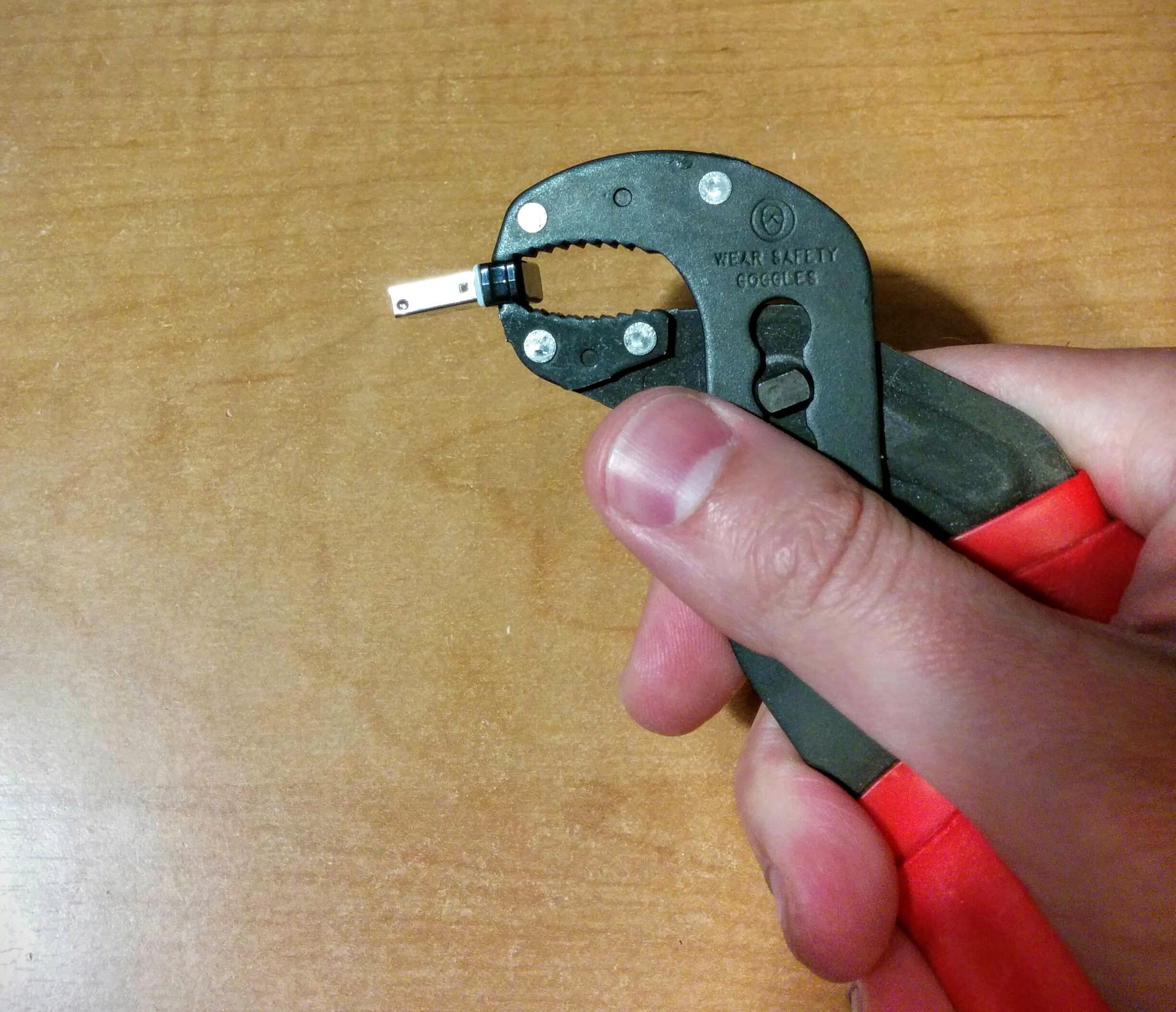
A little squeeze from a pair of pliers and the glue holding the cap to the body cracks.

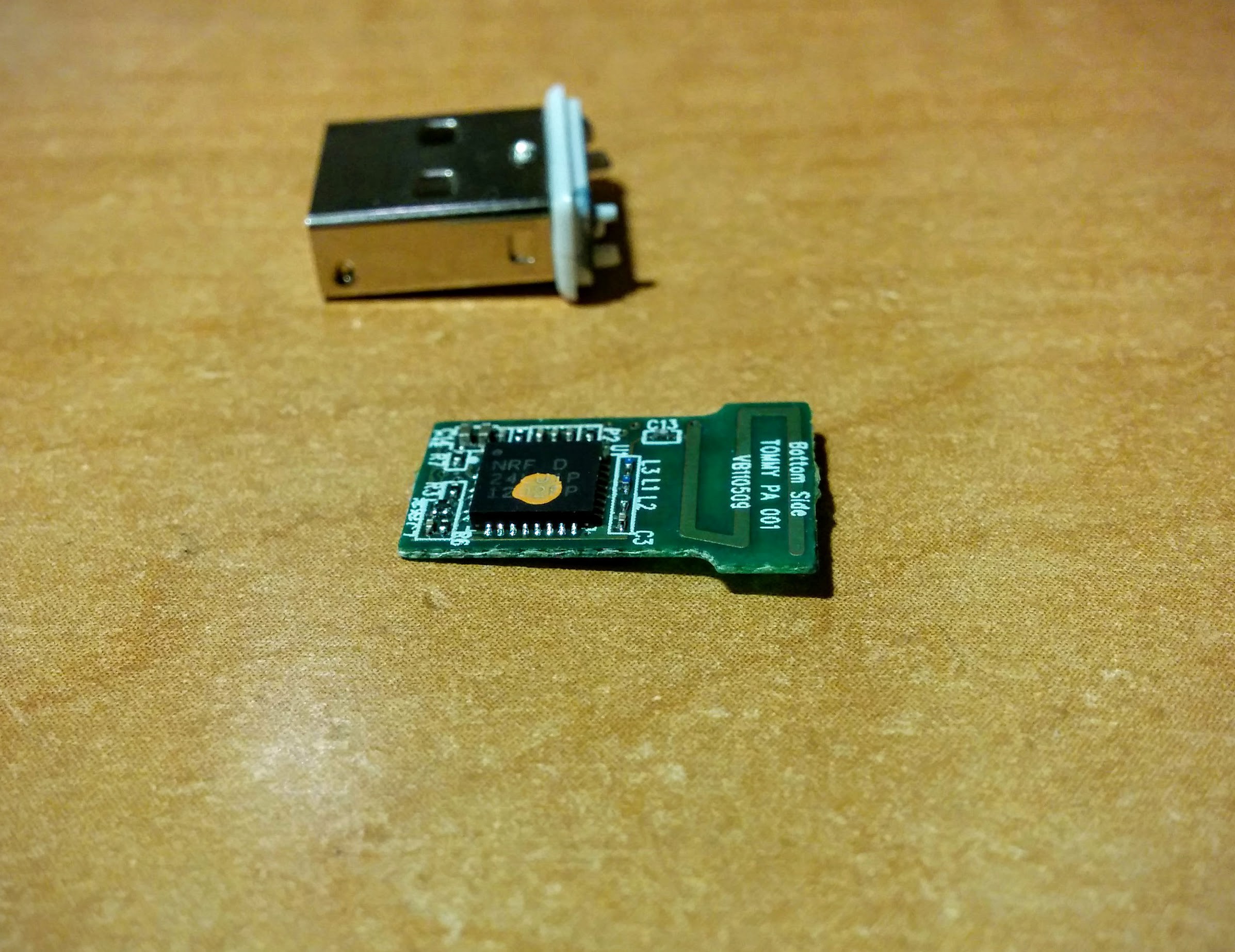
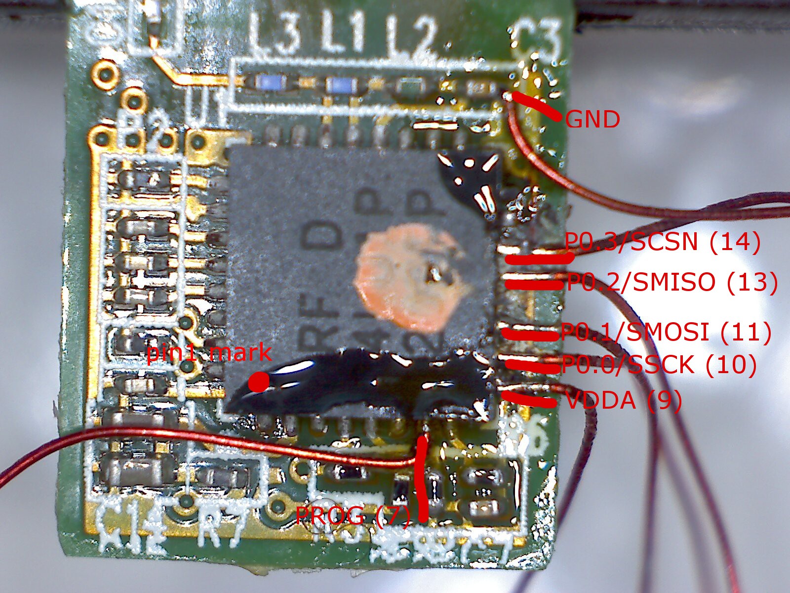
As you can see, no test points, just discretes and the chip. The orange dot is a dead giveaway that part or all of the firmware was programmed before the chip was soldered on the board.

I checked the pinout of the datasheet, and beeped out a few pins. The SPI port, VCC, and ground are all available on the edge of the package facing the camera above, while PROG is on one of the resistors to the bottom left. Fortunately the SPI port pins are unconnected. Unpleasant, but not impossible with some magnet wire.
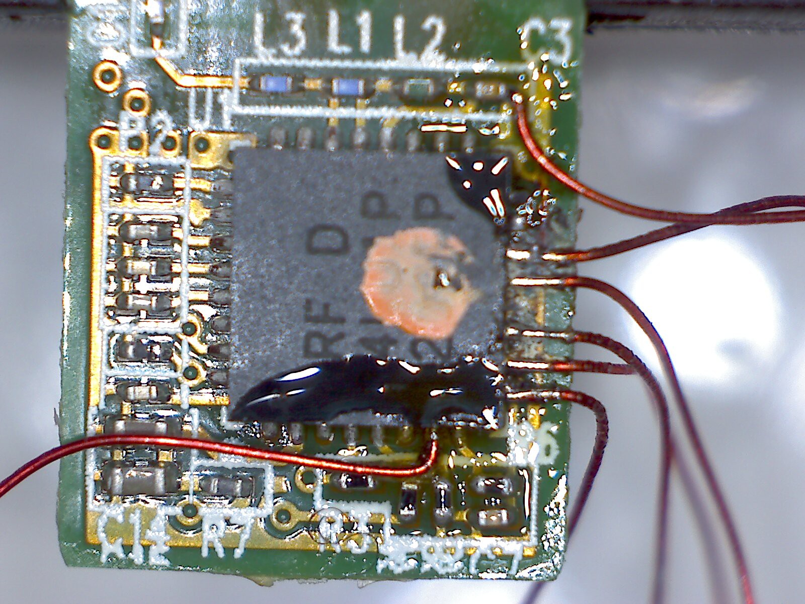
This went much faster than you might expect. Magnet wire is designed so that solder cooks off the enamel insulation. So by carefully tinning the tip of the wires and using plenty of flux on the PCB, it's easy to solder small targets like QFN feet.

My iron has a 1/16" chisel tip, which is great for cozying up to the tiny exposed QFN pads. To keep from desoldering neighboring wires, I tacked wires down the edge with the SPI port sequentially. With good lighting I didn't need a microscope during soldering, though I used my cheapo USB magnified camera to inspect the work afterwards. I ended up picking off GND from a bypass cap since the ground plane at the QFP lead was too heavy to solder in those close quarters, but everything else was soldered to the QFP.

With all the wires in place I used double stick tape to hold it tight to a breadboard. The tape was unexpectedly helpful in holding the wires as a sort of strain relief. I ran the free ends of the wire perpendicular to pins on a header I put on the board, tacked each lead, and trimmed them.
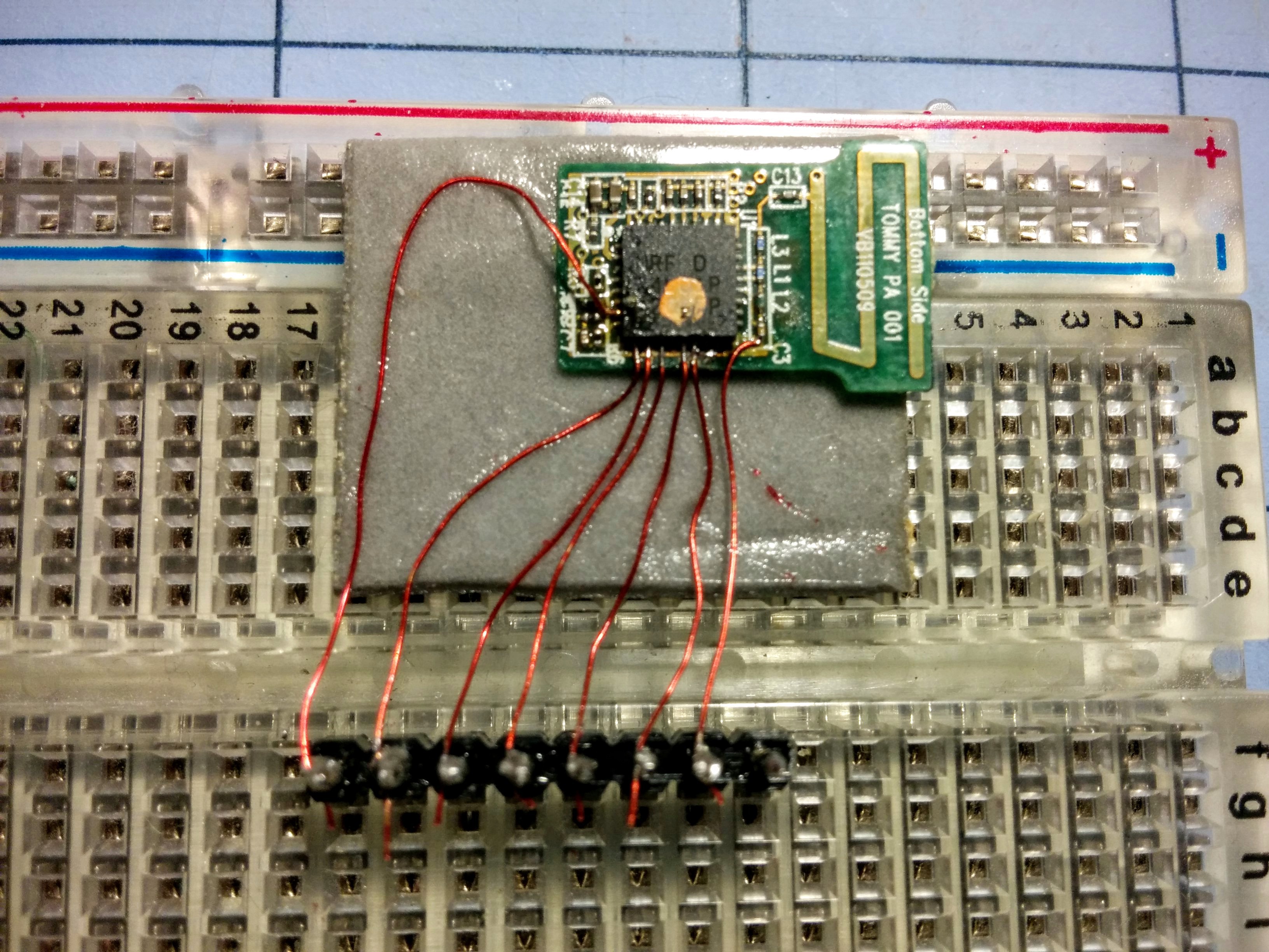
I then followed the wiki to wire each signal to a pin on a Bus Pirate.
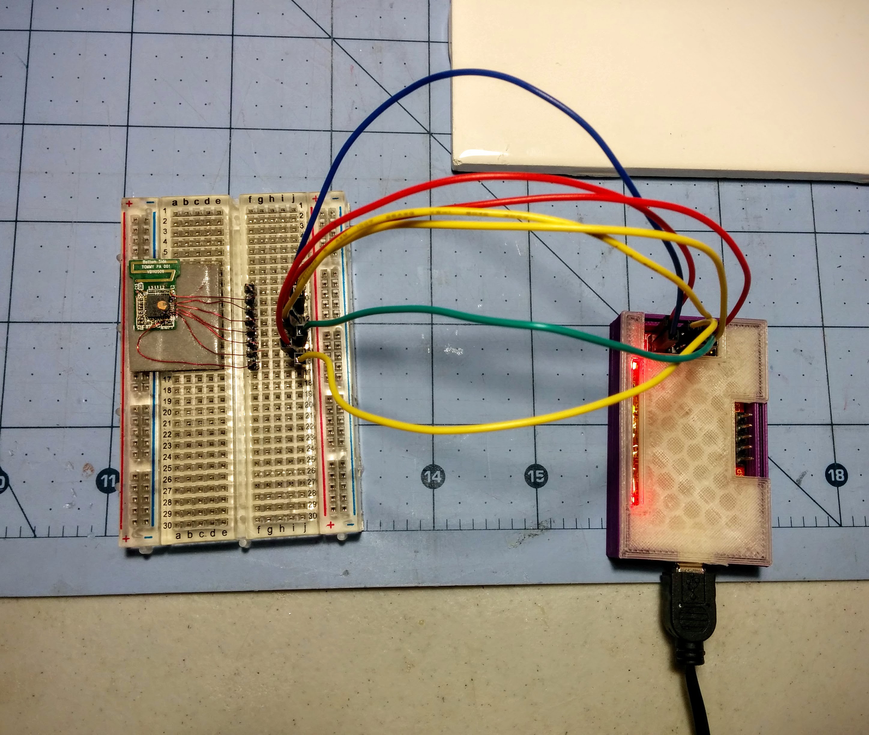
This took about 45 minutes from start to finish for the hardware work.

Software

I started out with the buspirate_nrf24lu1 project on Github. This is the script Bitcraze recommends on their wiki for recovering a Crazyradio with a Bus Pirate. buspirate_nrf24lu1 is a Perl script that works on OSX or Linux (after cpanning Device::SerialPort) to erase the nRF24LU1 and write a binary blob to flash.

Before I cracked apart the dongle, I looked at the GPIO and peripheral requirements for Crazyradio. There are only a few GPIOs on the nRF24LU1+, and Crazyradio only uses two for LEDs (Crazyradio PA uses an extra one for controlling the amp). The dongle uses none of the GPIOs, so it looked like it should work without any changes.

My first attempt at running this seemed to work, but complained about the status register being incorrect (0x24 and not 0x20) before erasing. The datasheet decodes this to WREN and RDISMB set, with WREN being expected (enable writes, since it's about to do an erase) and RDISMB informing that the main flash space readback is disabled. Although this shouldn't hurt Crazyradio, I didn't want to take any chance that could only be fixed by soldering to the SPI port again.

I added commands to erase the infopage, a separate flash space for unique configuration data. The field that locks reads and writes to certain memory spaces lives here. That seemed to fix the error message, and the flash of the firmware binary in the repo completed after 5 minutes....

Read more »

  • 1 × Logitech Unifying Receiver wireless mouse doodad to repurpose
  • 1 × Magnet wire not sure about gauge
  • 1 × 7 pin 0.100" inline header Dupont SIP style
  • 1 × Small breadboard
  • 1 × Double stick tape just enough to stick the module down and strain relief the wires

View all 8 components

  • Bonus motivation

    ajlitt07/17/2015 at 14:08 0 comments

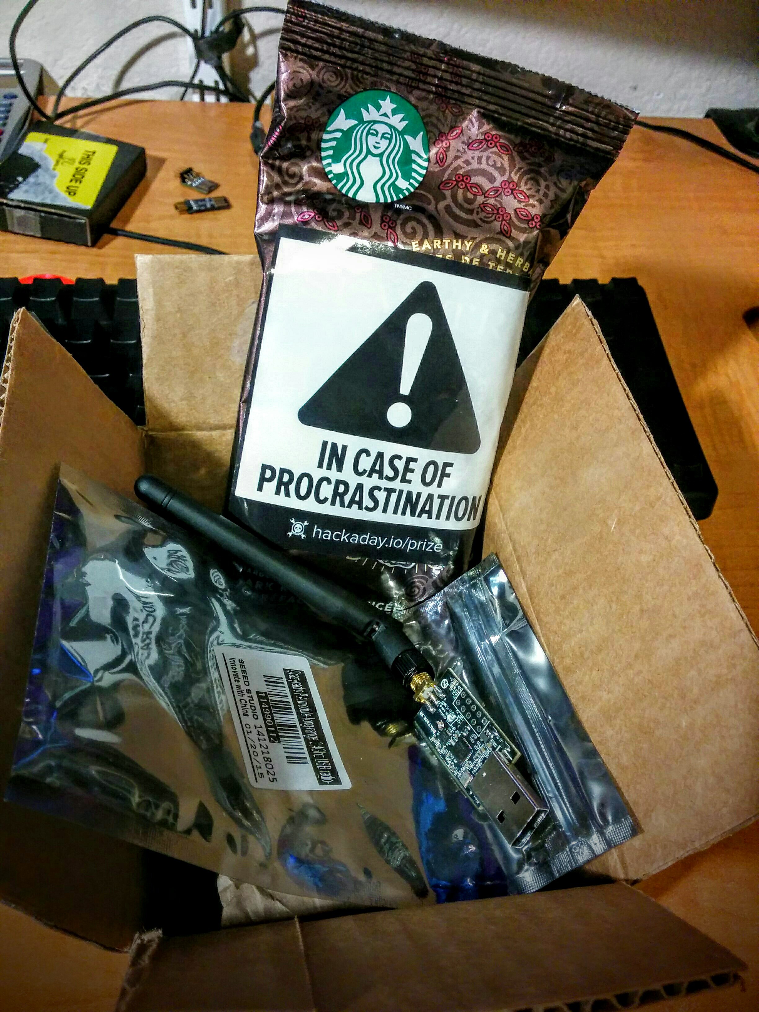
    I got a legit Crazyradio PE today from the HaD store, and got more in the box than I ordered:

    I'm not slacking on TBD, promise...

  • Too much fun, didn't sleep

    ajlitt07/14/2015 at 17:47 0 comments

    Well I took my trusty USB microscope to the MPU9050, the tiny QFN that's been problematic on some Crazyflie 2.0 builds, and noticed a lack of fillets on the edges of the QFN pads. I had a "it's a UNIX system, I know this" moment from all the QFN soldering on my Tiny Bit Dingus project.

    I put a little flux on the edges of the package, a little solder on my iron's chisel tip, and went around slowly heating the pins. Using flux with this kind of rework is misleading since it's hard to see the joint until you clean it off. But after cleaning and a check for shorts it booted right up with the entire IMU responding.

    I assembled the rest of the quad, balanced the props while the battery took its first charge, and stayed up way too late playing.

  • The radio is alive. The quad is dead.

    ajlitt07/14/2015 at 02:56 0 comments

    Got my Crazyflie in the mail today. I frantically opened the package, admired all the parts, and hooked the main board up to my PC to see if I could connect. cfclient saw the Crazyflie on the radio and connected cleanly. 100% signal strength in the client app with the radio and quad just a few feet apart.

    But the contents of the console window weren't so positive: the self-test failed to find any of the IMU devices on the I2C bus. I beeped out the bus at the pullups, and there don't seem to be any shorts. The forum suggests this is not uncommon and likely a soldering problem.

    I'm sure I can get it replaced or repaired by Bitcraze. Regardless I'm considering this project a success.

  • It's alive, maybe

    ajlitt07/12/2015 at 07:09 0 comments

    So I was one of the lucky winners of a Crazyflie 2.0 in one of the HaD contests. I cheaped out when ordering and neglected to buy the Crazyradio PA. I assumed it was necessary only for long range flight. You know what they say about assuming.

    Since ordering I've been reading Bitcraze's excellent wiki and forum, and it seems like most of the fun to be had involves a PC or RPi and the Crazyradio. I happened to know that the Logitech Unifying Receiver that my spare laptop mouse uses is based on the same chip as the Crazyradio. The Bitcraze wiki explains how the firmware and bootloader on the Crazyradio can be recovered over SPI with a JTAG adapter or Bus Pirate, so I thought it might be worth it to try the procedure on the mouse receiver while I wait for my toy to arrive.

    Long story short: After some soldering and screwing around with the programmer, I got this dongle to run the Crazyradio firmware. The Crazyradio DFU programmer works, and the cfclient flight control detects it properly.

    Without the Crazyflie I can't tell if it's actually working though, so there's that. I also don't have much hope that the range will be any different than BLE. Both Crazyradio models use high gain external antennas, while this uses a tiny zig zagged dipole PCB trace.

View all 4 project logs

  • 1
    Step 1

    WARNING: there is no turning back. After running the flash script the original Unifying Receiver firmware can't be restored.

  • 2
    Step 2

    Separate the black plastic cap from the white plastic frame. Lightly crimp the cap with pliers while pulling. The radio module slides out.

  • 3
    Step 3

    Flux the pads to be soldered, then tin and tack magnet wire to these pins:

View all 13 instructions

Enjoy this project?

Share

Discussions

Alan Rager wrote 05/22/2017 at 18:16 point
After I found your project, I found this one: https://github.com/BastilleResearch/mousejack They seem to have found a way to flash the unifying receiver over USB. Does this mean you could feasibly drop the crazyradio firmware on without even cracking the case?

  Are you sure? yes | no

Similar Projects

Does this project spark your interest?

Become a member to follow this project and never miss any updates