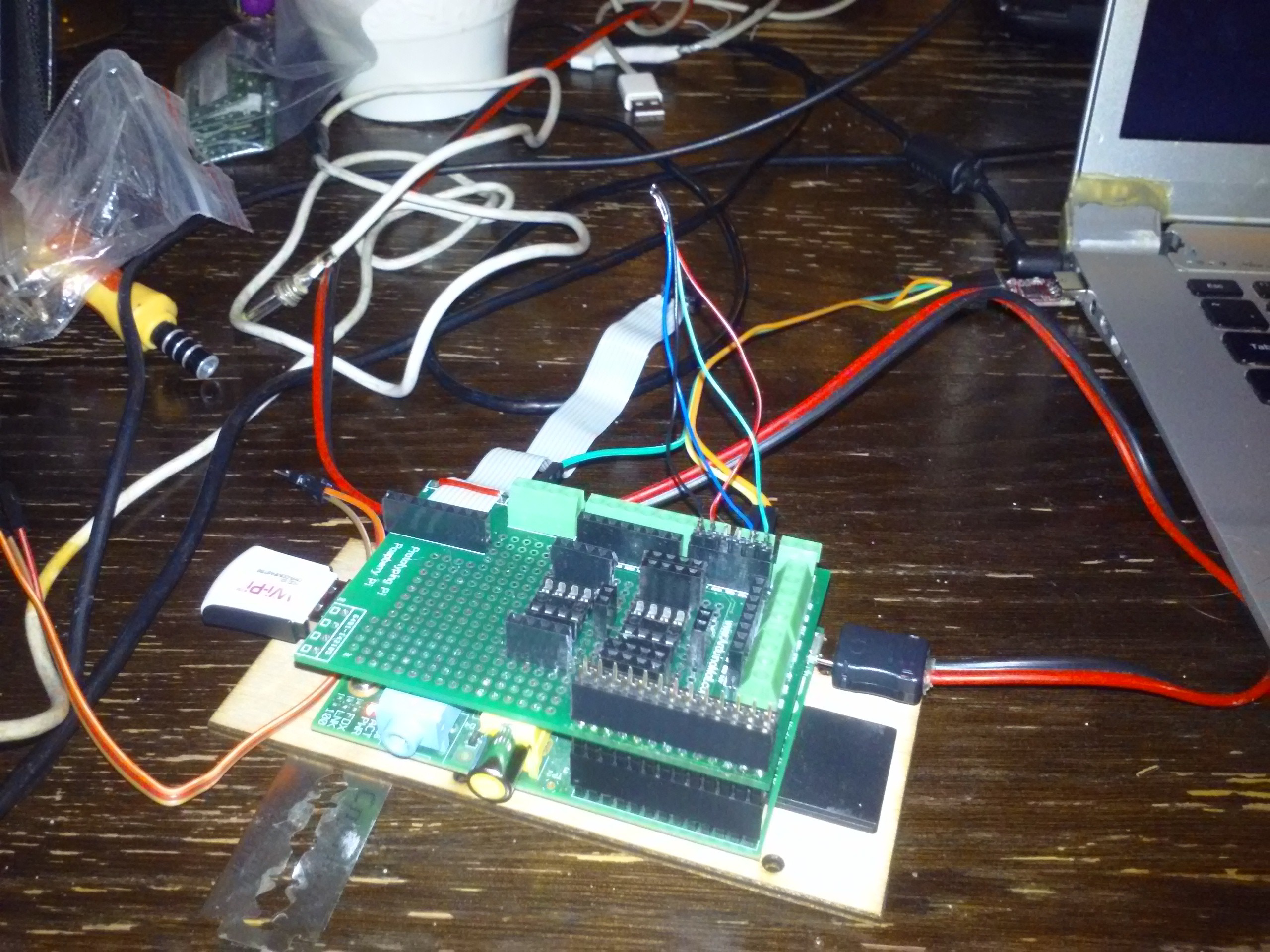
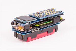
Close
0%
0%

Raspberry Pi portable workbench(Project Christoph)

Raspberry Pi+prototyping shield+sockets&cables&software to hold it all together to do all sorts of EE things.

Similar projects worth following
This is a device I've needed for a long time. Raspberry Pi has good community support, is maybe the most available Linux SBC and therefore is really good to use as a tool for repairs and development in general - and I have some spares I can put to work. It is my BusPirate, flash/AVR/PIC/whatever programmer, music player for creating good work atmosphere and whatever I'll need to get the work done.

Features currently implemented&tested:
- SPI flash programmer
- PIC programmer
- I2C EEPROM programmer
... Yeah, I know that's not much =) I add features as soon as I need them, though.
Writeups are to come as soon as I add capabilities.

tl;dw (too lazy;didn't write) I use a copy of this Adafruit shield for my prototyping:

It's got some DIP sockets in it, and I plan to add more - maybe a socket that'd go across the entire board =) I'll do a more detailed writeup on the hardware part when I finish the case, basically, when I get some time to draw some more parts of my case for laser cutting - which might be complicated because my goal is to make the case universal enough to be useable for all the generation of Raspberries, including all the cutouts and, of course, GPIO header positioning =) You can see some photos of the device itself in the writeups though.
I also use a Raspberry Pi A - yes, from the first generation. It's useless for many projects because of lack of network connectivity&RAM, but it's great to breathe a new life into it in some permanent installation, and I don't really need USBs for most of the hardware hacking with this =)

  • 1 × Raspberry Pi A board
  • 1 × Adafruit Prototyping Pi shield (copy)
  • 2 × DIP sockets
  • 10 × Female sockets
  • 100 × Wires

View all 6 components

  • SPI flash programming install guide

    Arya05/09/2016 at 02:03 0 comments

    So, I've forgot an SD card of Project Christoph at home and I urgently need to flash a SPI BIOS flash. While I'm installing all my SPI tools on a fresh image, lemme make a log with instructions:

    apt-get install subversion usbutils build-essential libftdi1 libftdi-dev zlib1g-dev  libusb-dev
    svn co https://code.coreboot.org/svn/flashrom/trunk flashrom
    cd flashrom
    make CONFIG_ENABLE_LIBPCI_PROGRAMMERS=no  CONFIG_ENABLE_LIBUSB1_PROGRAMMERS=no
    Usage instructions:
    ./flashrom -p linux_spi:dev=/dev/spidev0.0 #Detecting the chip
    ./flashrom -p linux_spi:dev=/dev/spidev0.0,spispeed=8000 -r fw.bin #Reading firmware from it
    ./flashrom -p linux_spi:dev=/dev/spidev0.0,spispeed=8000 -r fw2.bin #Reading firmware again
    sha512sum fw.bin && sha512sum fw2.bin #Checking two images to see if SPI works OK
    
    ./flashrom -p linux_spi:dev=/dev/spidev0.0,spispeed=8000 -E #Erasing the chip
    ./flashrom -p linux_spi:dev=/dev/spidev0.0,spispeed=8000 -w image.bin #Writing image to the chip

    "spispeed" parameter, although not documented anywhere, means SPI speed in kHz, so 8000 is 8MHz - the fastest Pi can get AFAIK and the parameter that works quite well.

    I had plenty of problems today with a SPI flash labeled as W25Q64.W. It was a chip bought in China (like, the buyer was physically in China. Feels weird, right?), and by the datasheet claimed to be working at 1.8V and 1.8V only. It worked for me with all the logic and power shifted to 1.8, however, the readings weren't reliable and the flashing would never verify - the flash would erase correctly and read back as FFs, but writing to it would not get verified. I connected it to 3.3V - and not only it did not burn in flames, it did flash and read correctly. I spent 3 hours on this shit. Conclusion? Don't believe those Chinese-bought flash chips. The markings were looking totally legit, but it feels like a fake to me due to this inconsistency with the datasheet.

    This whole code piece sounds like a nice #pyLCI - Linux Control Interface application, but there's still a lot of UI elements I need to add, like file browser and so on.

  • Reflashing I2C EEPROMs while hacking an OVC3860 Bluetooth adapter

    Arya03/14/2016 at 19:30 3 comments

    I've got a friend who makes a living making custom speaker systems/headphones/laser cut things, and as with many fields today, it's got a lot to do with electronics. Many of the things he does are one-offs, thus, it makes sense to re-purpose some Chinese boards sometimes just for the sake of adding a feature. Think "Hey, maybe you could add Bluetooth to those speakers of mine?" And that's exactly what one of my "workdays" was about recently.

    There it is. A board he had spare, from an adapter which plugs into one of those iPod/iPhone docks which have built-in speakers, receives audio through Bluetooth and streams it to the said dock. Some of those docks have decent enough sound quality, thus it makes sense to add adapters, and some of those are just lacking Bluetooth, as we know, everything's better with Bluetooth. In the end, why have a dock that's suitable for your iPod but not for your Android phone?

    Anyway, he didn't need that adapter and it was suitable for the task. Normally, it would just be a simple job of soldering a couple of wires and leaving it inside the speaker - just look at these testpoints!

    But then, it wouldn't need me if it were so easy. He also wanted the adapter Bluetooth name replaced, since, you know, he's producing one-offs and putting his brand name on them so that people come and see - he's put a lot of work in these, and he really does - except for BT adapters, where it's no sense to reinvent the wheel. It'd be all good, but "I-WAVE" is not really his brand name, and it's not even nice-looking. Moreover, there wasn't really any process for changing it - as you can imagine with a custom product not even intended to be disassembled, not to mention soldered to.

    Yes, that chip on the left side has all the markings erased. Those dicks, why'd you do that? I don't even understand what it does. It doesn't seem to work with USB, and yet it seems to be connected to the 30-pin connector. It seems to be some kind of PIC, Chinese manufacturers love thise and placement of VCC/GND pins seems like it. Also, it might be connected to the OVC3860's UART.
    The OVC3860 seems to have been featured on Hackaday one time, and it seems it accepts custom AT commands. It also is available on more hackable modules that are intended to be connected to *duinos and such - here's one guy doing basically the same hack as me, and there seemed to be a nice forum thread ot two about it too. But whatever, I discovered them only later somehow, that's why you do your Google homework properly before hacking =D
    I had to take a closer look:

    Sorry for bad pics (that's the best camera I have). Anyway, if you don't see a 24C08 EEPROM, you'll have to take my word for it. And what's the best place for storing such things other than EEPROM?

    Now, let's return to my workbench. As you can see, the shield has the I2C pins broken out (this is not my shield, it's an exact copy though):

    Great. The only problem is alleged 5V-only operation, but AFAIK some 5V devices like this work on 3.3V, they just aren't tested on this. Anyway, I'll plug a male header in the 3V3-UART-I2C 2.54 female header and just solder wires to it:

    That way, I can plug/unplug this chip whenever I want. I also can add a female header to the board the EEPROM was soldered to, to avoid soldering the chip to the board every time I need to test a new firmware image:

    Now let's load dev-i2c, deadbug the EEPROM on wires the same way it was connected on the board, connect its VCC to the 3V3 supply and see if it's OK with 3V3, at least for basic operation:

    root@raspberrypi:~# i2cdetect -y -a 1
         0  1  2  3  4  5  6  7  8  9  a  b  c  d  e  f
    00: -- -- -- -- -- -- -- -- -- -- -- -- -- -- -- --
    10: -- -- -- -- -- -- -- -- -- -- -- -- -- -- -- --
    20: -- -- -- -- -- -- -- -- -- -- -- -- -- -- -- --
    30: -- -- -- -- -- -- -- -- -- -- -- -- -- -- -- --
    40: -- -- -- -- -- -- -- -- -- -- -- -- -- -- -- --
    50: 50 51 52 53 -- -- -- -- -- -- -- -- -- -- -- --
    60: -- -- -- -- -- -- -- -- -- -- -- -- -- -- -- --
    70: -- -- -- -- -- -- --...
    Read more »

  • SPI ROM interfacing (BIOS/router ROMs/logging etc.)

    Arya03/07/2016 at 07:17 0 comments

    I sometimes need to read and write SPI flash memory chips. Furthermore, I just got a task to re-flash a BIOS on a motherboard, so I had some additional motivation to make me a tool that does it. I've heard good things about FlashROM, it's a pretty versatile package which is open-source and supports many programming platforms, including Raspberry Pi.


    The motherboard (MSI FM2-A75MA-P33) had a SOIC SPI flash chip which was soldered on, but all the pins were available on a header, pinout for which seemed to be already reverse-engineered and available on the Internet.
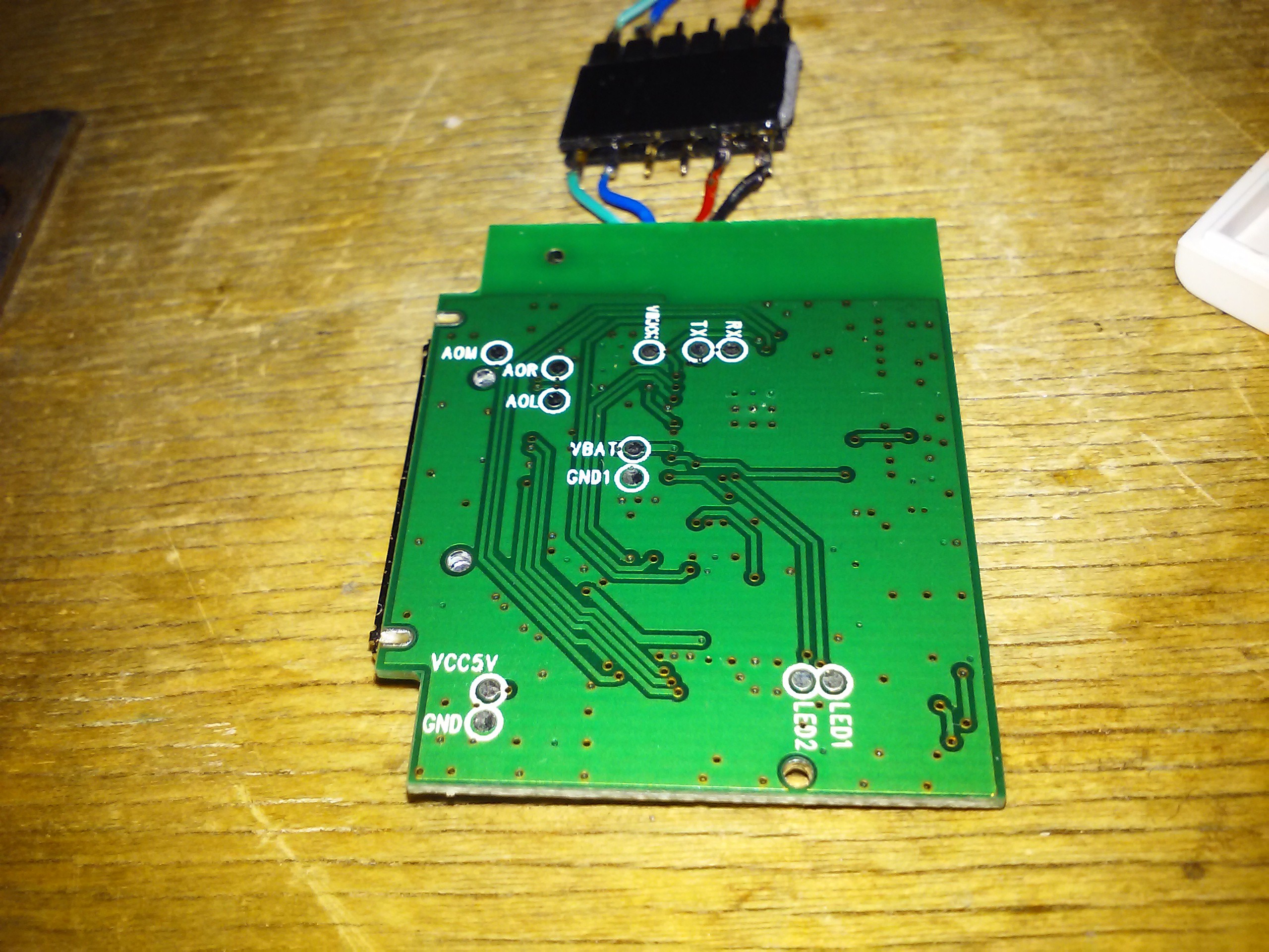
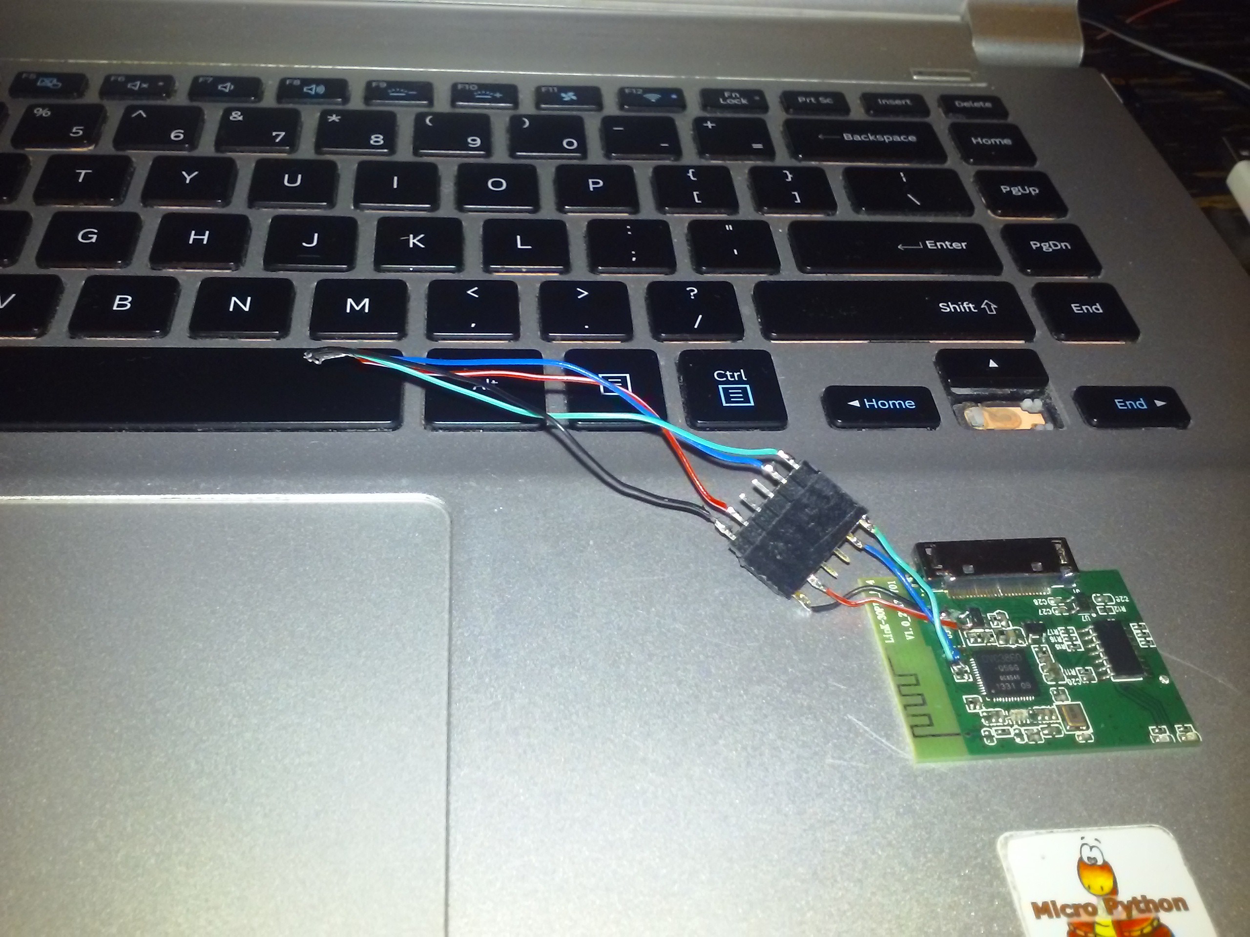
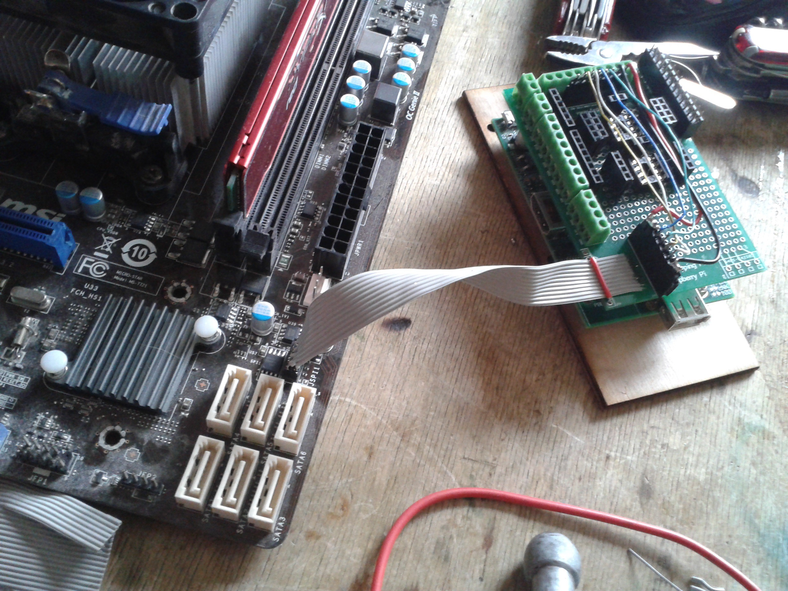
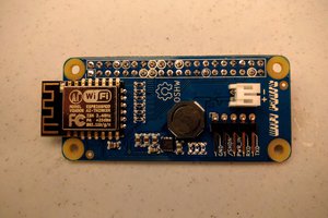
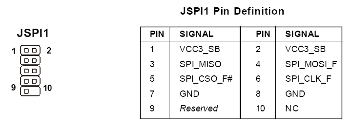
    The header had 2MM spacing between pins, but I bought a corresponding connector for this and soldered a ribbon cable with proper spacing to it. I then soldered this cable to the prototyping shield I use and made a cable which'd connect it to the proper SPI&power pins.


    Next, I needed to download and compile flashrom. It was really fast, I just needed to apt-get some library dev versions. It also recognised the BIOS chip I connected to it, which was marvellous - it means it's able to communicate with the chip without any problems.
    I read the chip's contents and, sure enough, it was erased - except for some areas. Seems like BIOS flashing process started, but never finished. I erased the chip and wrote an image I got on the MSI website (those bastards didn't provide proper recovery BINs for latest versions, though). It all went without a hitch, and I went on to battle some other BIOS troubles:


    The SPI-to-ribbon matching cable packed in a bag so as to avoid possible future wire mismatches, as well as never need to make it again:

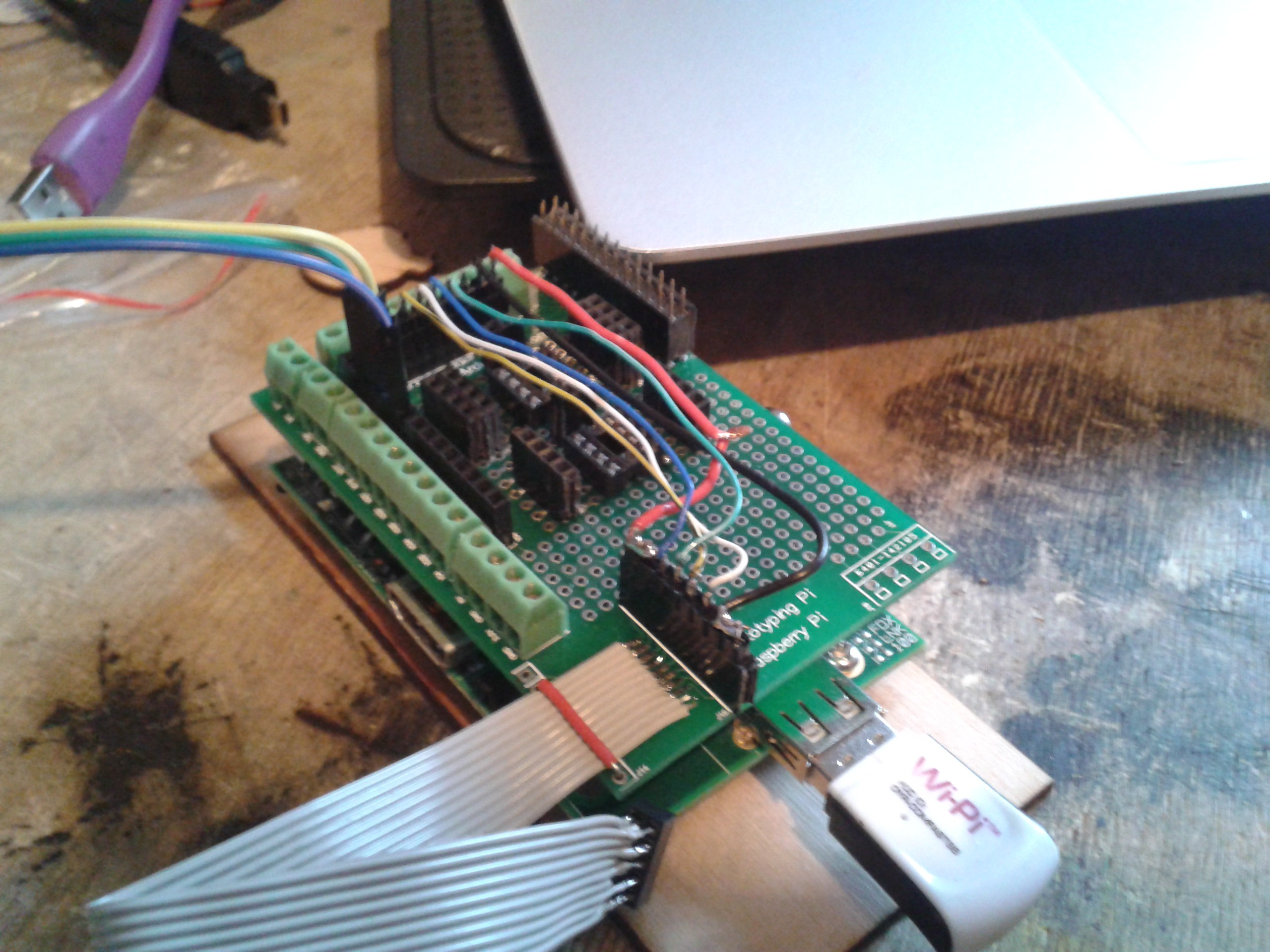
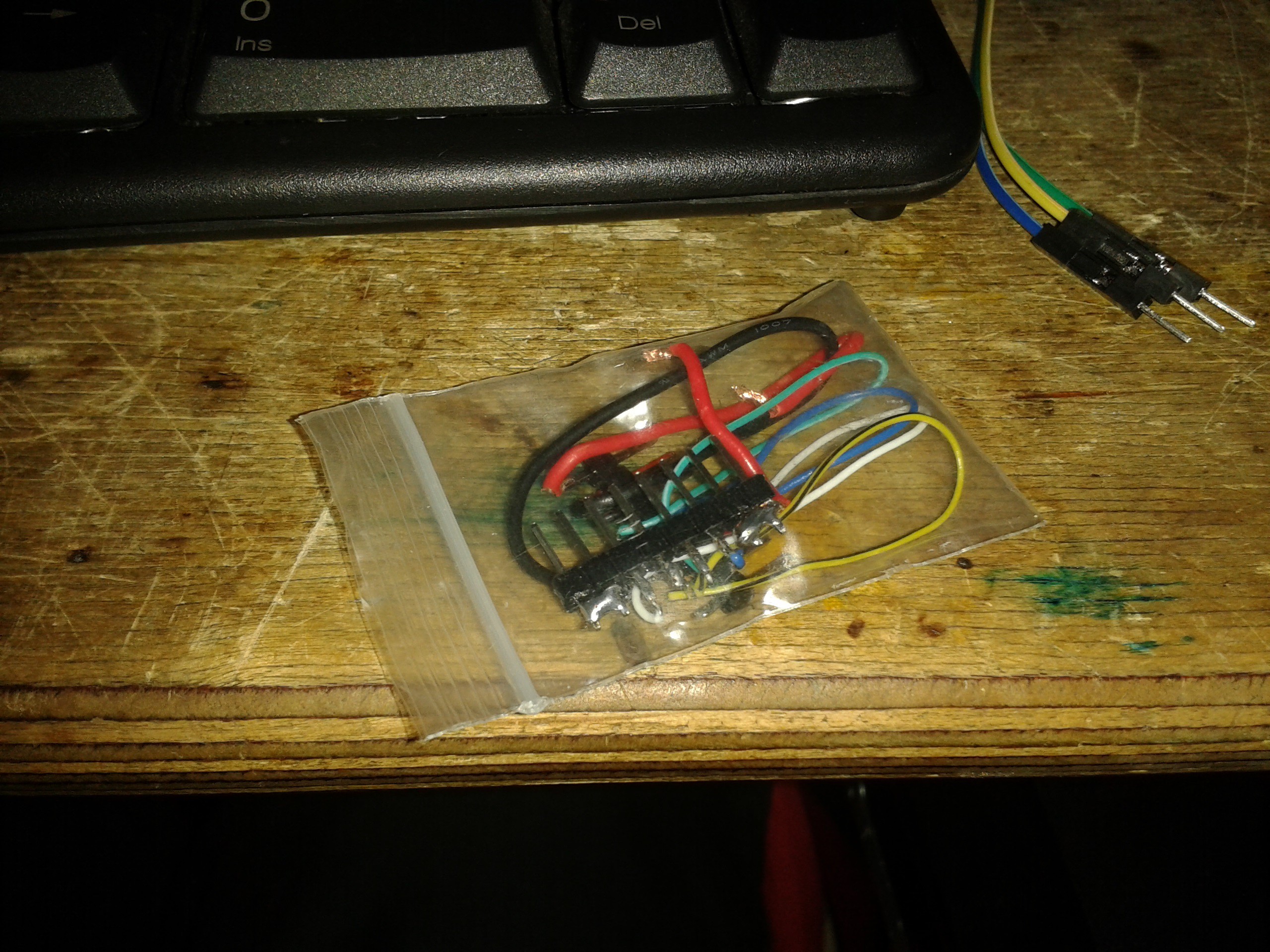
    That way, I can label it something like "MSI BIOS adapter", and next time I just plug it in the same way and not worry about searching for pinouts, soldering or checking connections etc.

    Some concerns:
    If you're doing In-System Programming (with chip still soldered to the mainboard and leads attached to the chip), you might run into the issue that you might backpower the mainboard. In my case, the current on 3V3 line was around 300mA - and my gut feeling told me this wasn't exactly consumption of the flash chip alone, but at least it didn't hurt anything. It might be worse in other cases, in my case RPi just rebooted every time I'd connect the chip to it - so I tried not to disconnect it. In some cases though, as it is with router boards, you need to avoid backpowering. I have a SBC which will simply power up and try to read the flash as soon as 3V3 is applied, and that's not acceptable if you're trying to flash the ROM. I guess you could hold RESET signal of that SBC low though, yet to check this. I also guess old tricks with lifting pads off the board still apply, too.

View all 3 project logs

Enjoy this project?

Share

Discussions

jaromir.sukuba wrote 01/01/2017 at 11:27 point

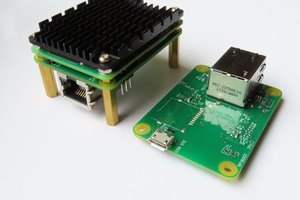
I assume this work-bench will have bigass double throw main switch with labels: "Bench-on" and "Bench-off".

  Are you sure? yes | no

usedbytes wrote 03/22/2016 at 08:03 point

My project 'Gadget' is based around the software side of this kind of setup, perhaps you'd be interested? Do you have any kind of buffer or level shifting for interfacing 5v/1.8v devices? I think that's the main limitation for me

  Are you sure? yes | no

Arya wrote 03/22/2016 at 10:03 point

Cool project, man! I'll look in your code later when I have some time, but the logs are promising. I have some of those really cheap I2C level shifters, as well as some unidirectional buffer ICs - and a GTL2003 I found available in a local shop and immediately bought =) Are you looking for something?

  Are you sure? yes | no

usedbytes wrote 03/22/2016 at 10:20 point

There's no real code yet, just me hacking around at the moment. I finally got my new Zero set up yesterday so I can get on with the code in earnest.

I was just curious really - I'd never seen that GTL2003 before, it looks fantastic. Certainly that's some good food-for-thought

  Are you sure? yes | no

Arya wrote 03/22/2016 at 13:33 point

Oh, great! What are the interfaces you'll be using that for? I saw you mentioning AVR programming and I2C interfaces, I've also programmed PICs with picpgm and SPI eeproms with flashrom, as you might have read already. I'll also set up a cool interface for this thing... This is my new thing I stuff everywhere because it's so useful - pyLCS https://hackaday.io/project/10001 . The difference is that with pyLCS I can make my Pi a standalone programmer you just plug in MicroUSB for power/charging and use some buttons to navigate the interface, upload/download firmwares to/from chips, maybe connect to a network and use the CLI to do some more advanced things, or maybe set up a hotspot with bridging, maybe a TFTP server, or maybe use it as a frontend for my BitScope Micro... To sum up, my thing is planned to be more self-contained, while yours will leverage processing power of desktop PCs. Anyway, I think we'll exchange quite a bit of information =)

Yeah, it was like "I'll just search for local ULN2003 prices by typing 2003 in the search... Oh, what is that thing?" Both SPI and I2C compatible, it's just that one side has to be higher voltage than another, so you can't really do 3.3V to 5V and then 3.3V to 1.8V without moving pins around physically. Guess one could work around that if necessary, I even more or less start to imagine how to =)

  Are you sure? yes | no

usedbytes wrote 03/23/2016 at 17:02 point

Yeah basically I want to be able to interface <any> (1.8-5v) voltage to the Pi on any protocol. I see I would need to swap the "high" side somehow so that's a shame, but probably workable (though I can't see how to do it without taking up some I/O :-(. Perhaps I can hijack the HDMI port's i2c bus for a configuration microcontroller)

I like the idea of pyLCS - I've done a similar thing with an AVR and HD44780 but for microcontroller pojects so no real software framework on the "host" side, just a UART read/write interface: write goes to screen, read comes from buttons. I still have the hardware but I think the software got lost a long time ago.

I think we have two very complimentary projects :-)

I'm entirely focussing on "Pi as a peripheral" at the moment, but I reserve the right to pull in any modules you open source when I want to extend the scope ;-)

  Are you sure? yes | no

Arya wrote 03/30/2016 at 16:47 point

Sorry, somehow didn't see your comment =(
You don't necessarily need to use that GTL. Alternatively, there's always an option to swap it manually or, I don't know, have 2 GTL boards =D

Had a lot of updates on pyLCS this week, i'm releasing it in a few days If you think that'd give some value to your project, feel free to contact me on help/instructions =) I've made myself a simple I2C scanner app, for example, and it's tremendously helpful when I need to simply debug whether things are connected properly. I also think it'd be easy to implement I2C read functionality, maybe even I2C write =)

  Are you sure? yes | no

Similar Projects

Does this project spark your interest?

Become a member to follow this project and never miss any updates