 Hexabitz
Concept in a Nutshell
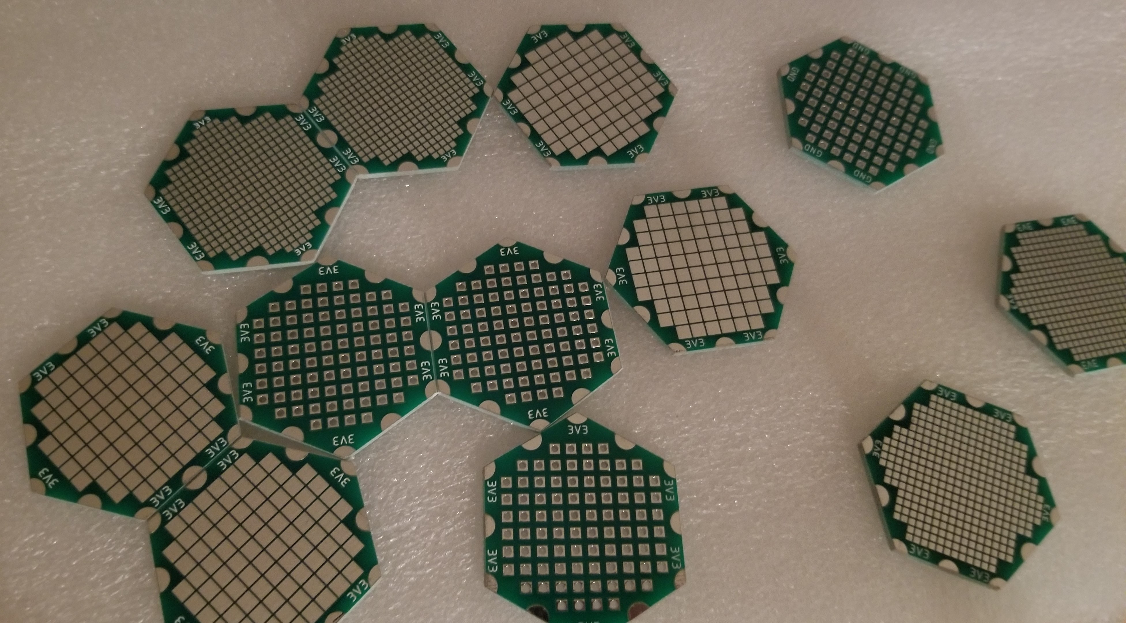
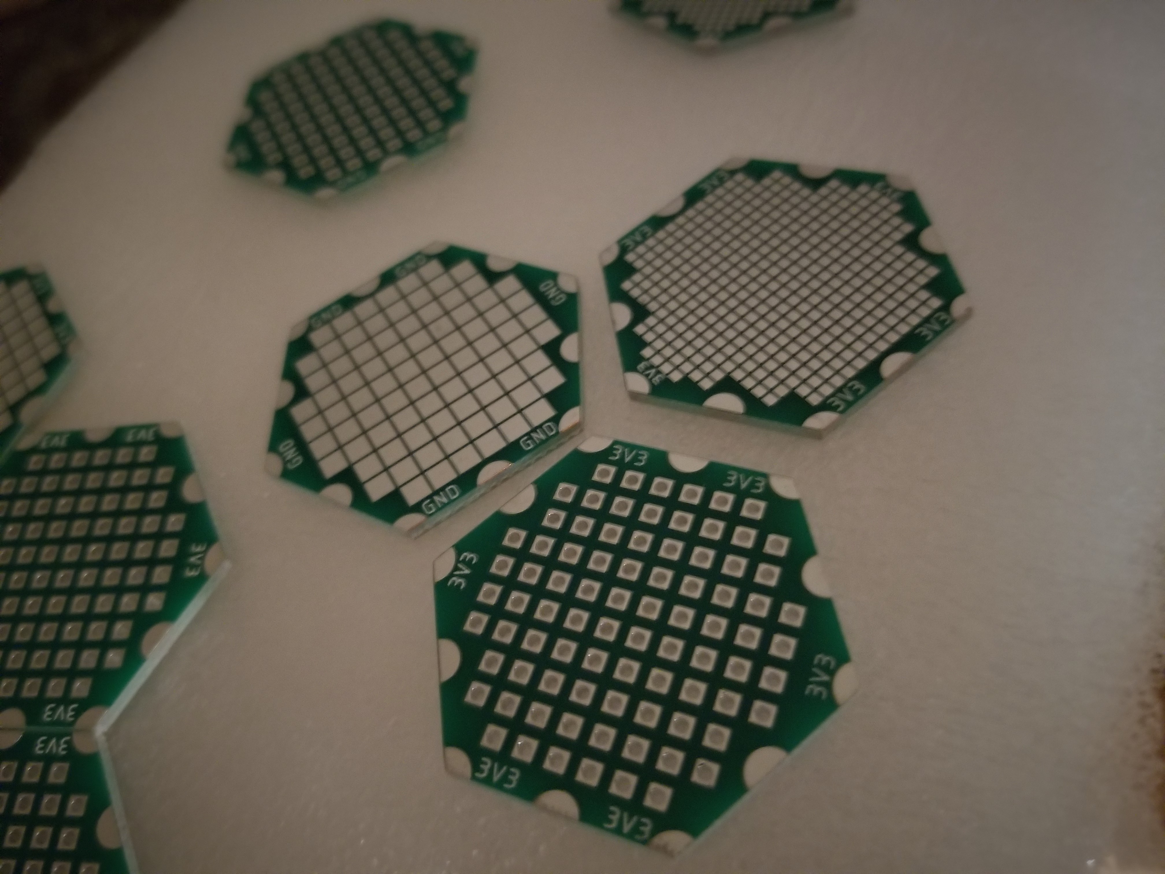
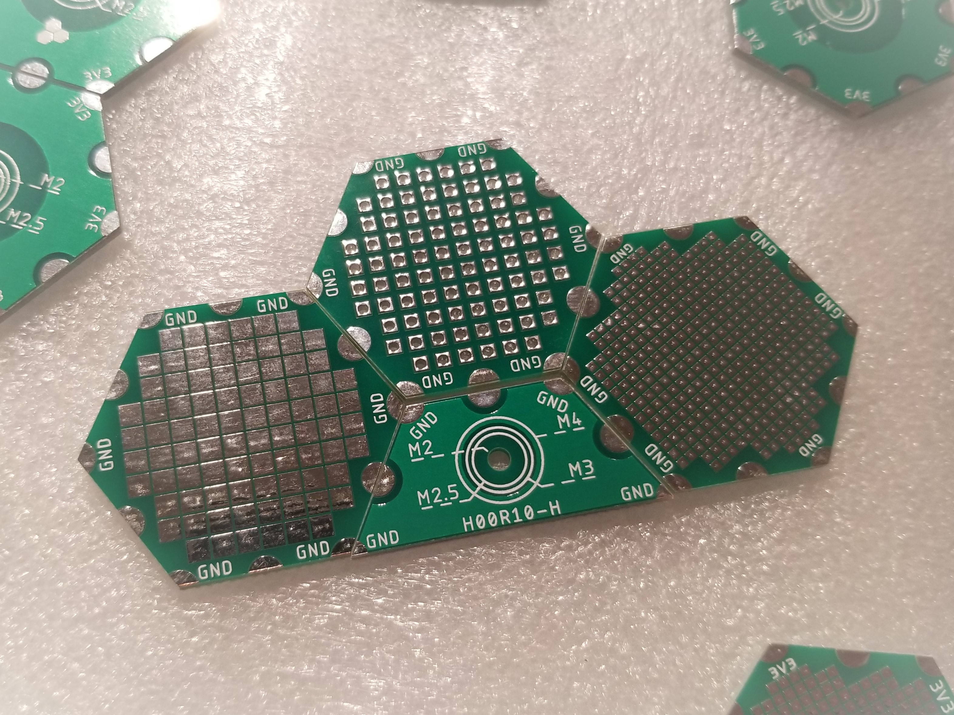
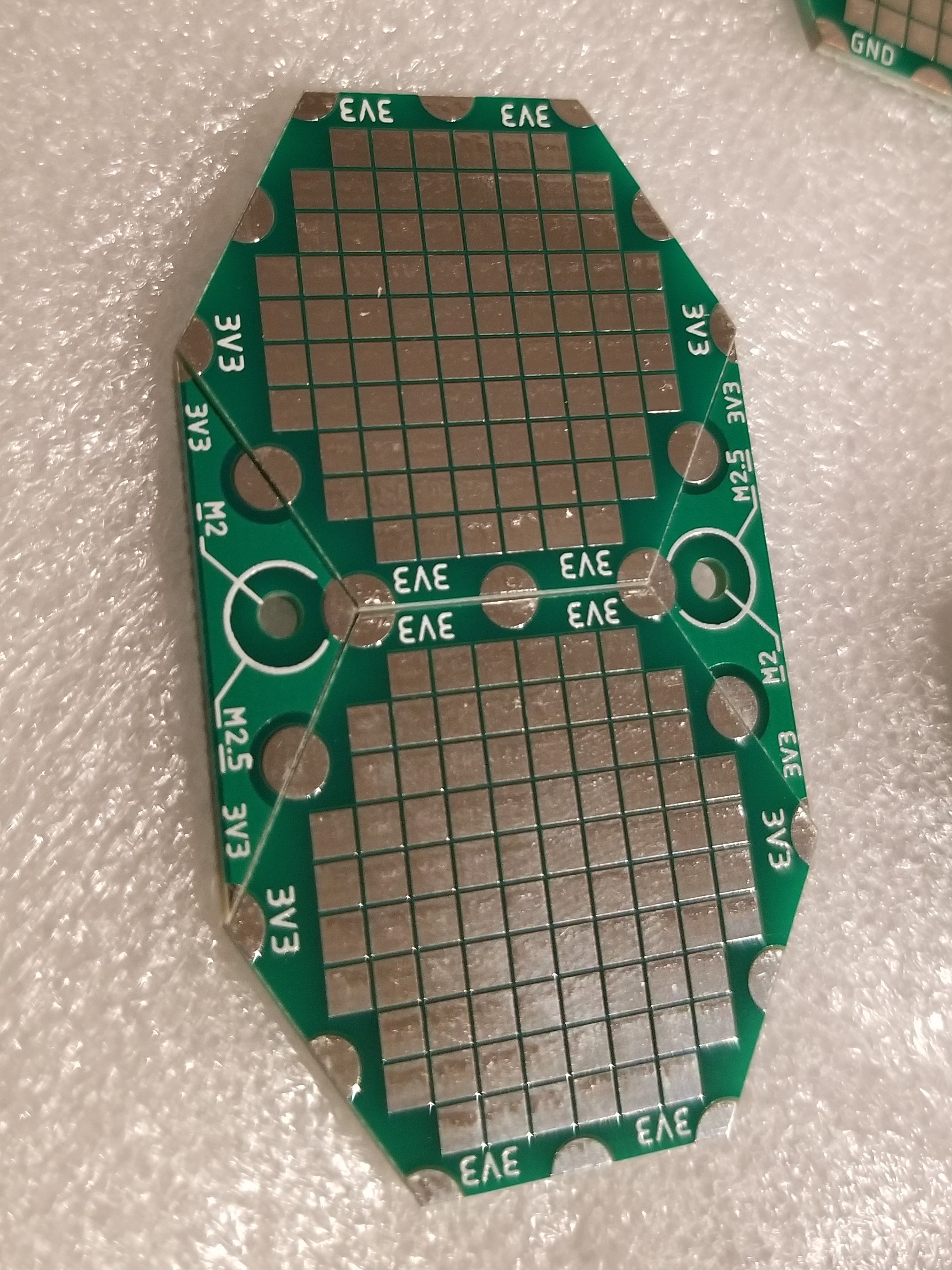
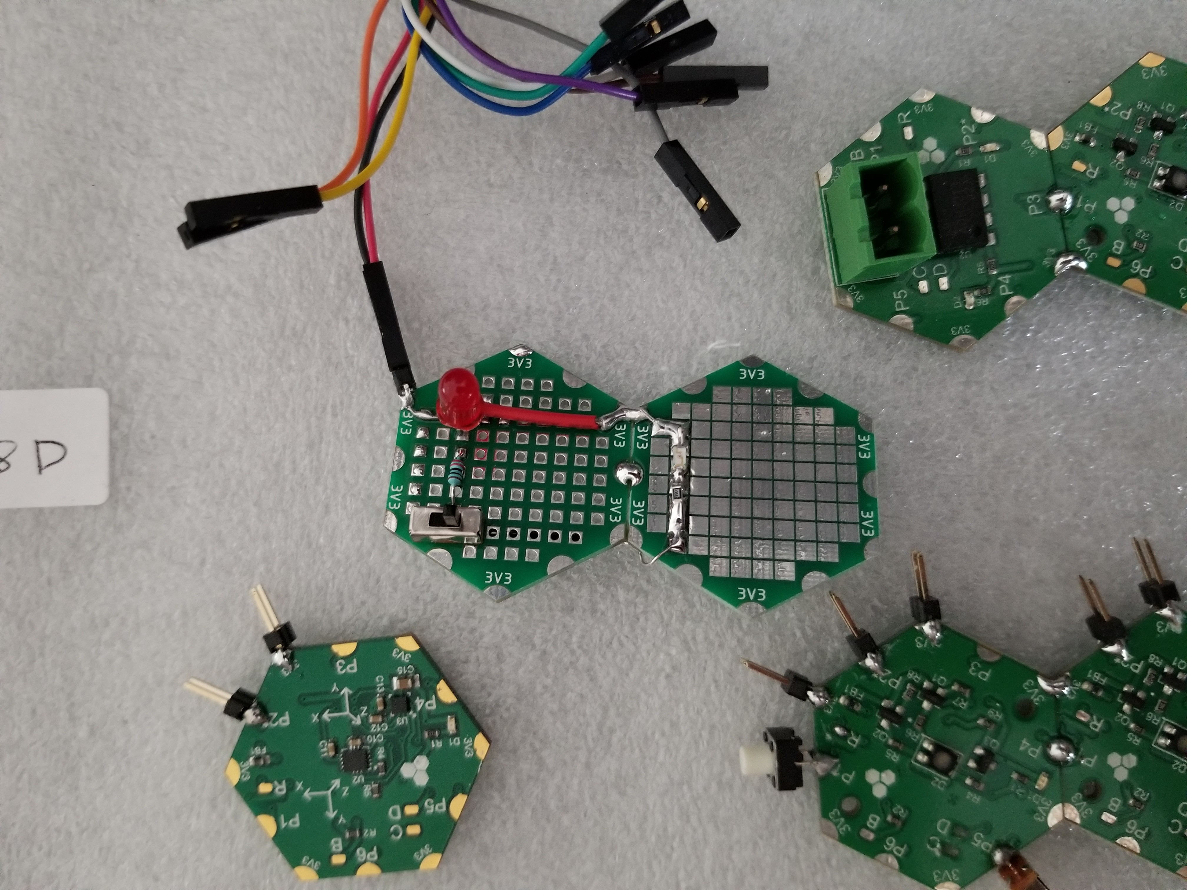
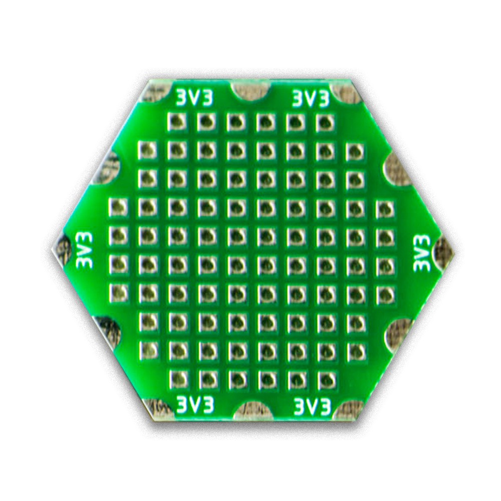
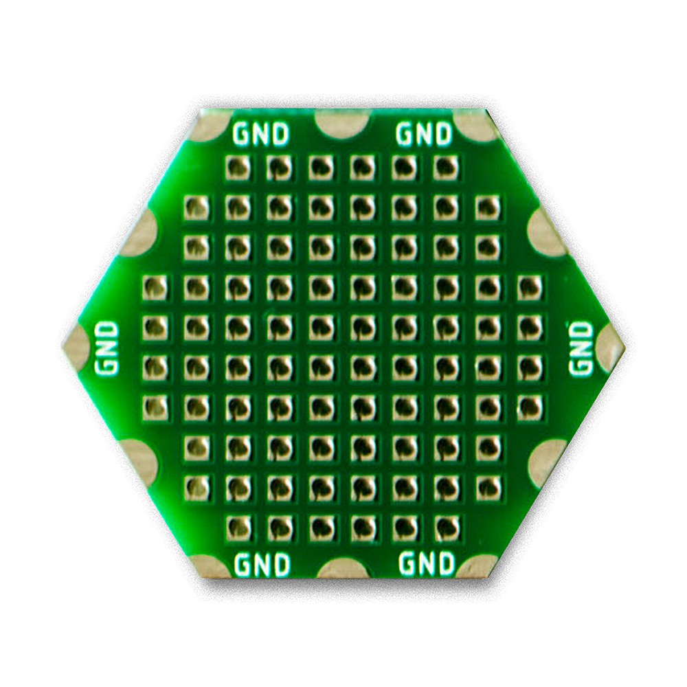
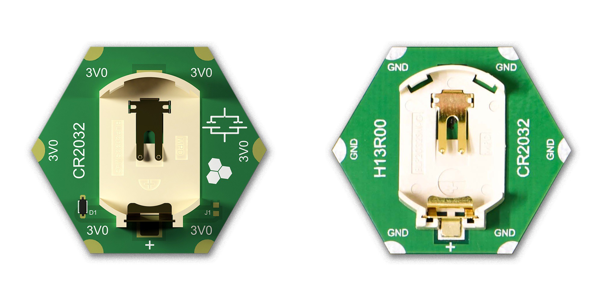
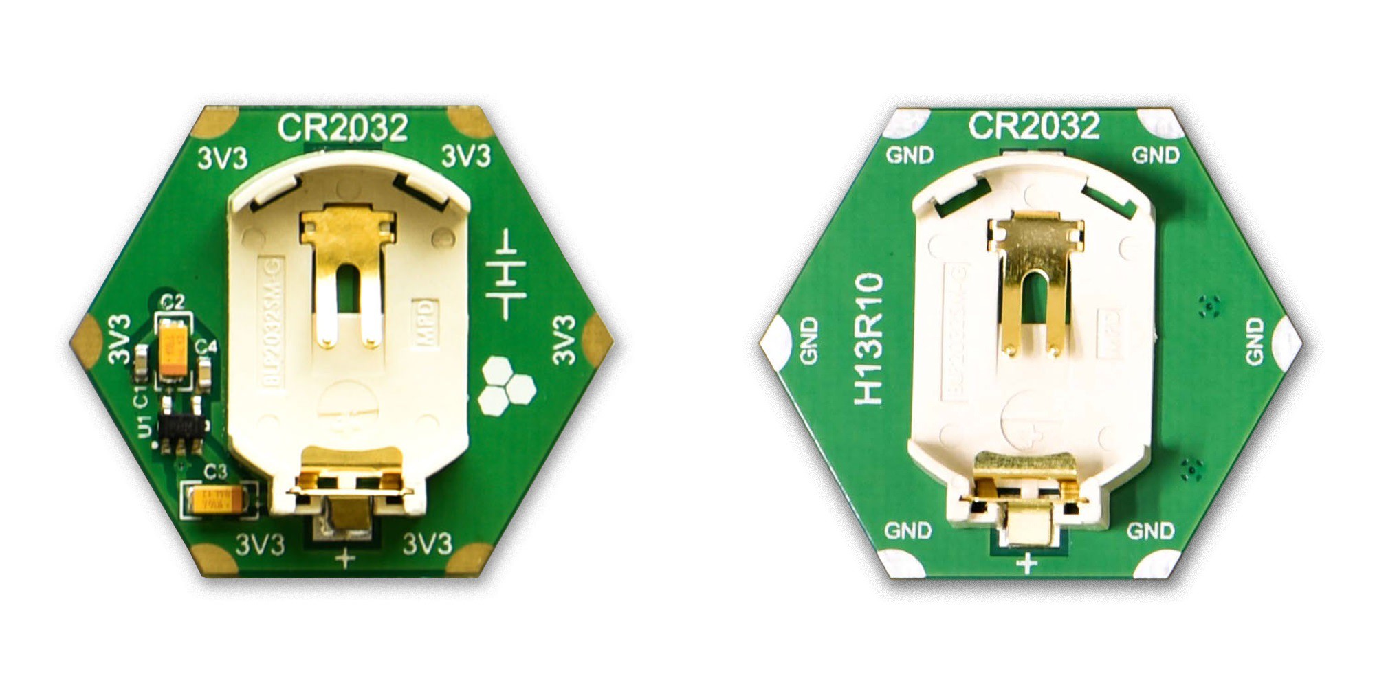
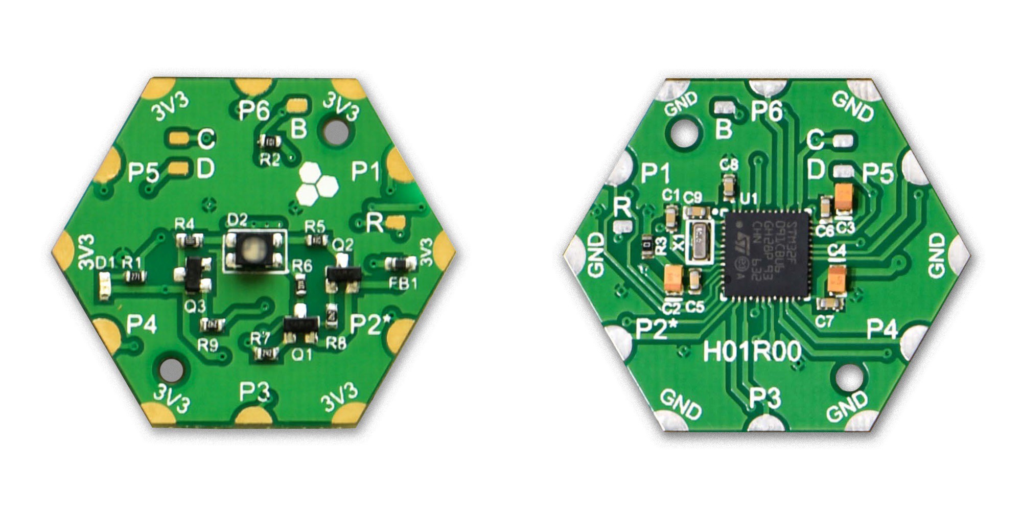
Hexabitz is a novel modular electronic prototyping system. Each module or bit comes in a specific shape or size. Either hexagon (hence the name Hexabitz), pentagon, rectangle, square or triangle. Modules are soldered together horizontally to make larger electronic boards or arrays. You can easily combine modules in any shape or configuration you want. The resulting board will be close to custom-made ones in terms of size, weight and form-factor.
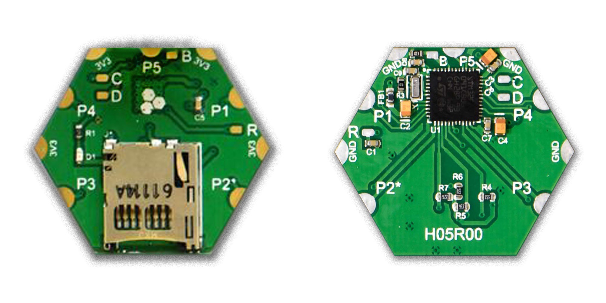
Each Hexabitz module has a specific functionality and a small MCU on the back side. MCUs are used to connect modules together in a wired-mesh network and to execute various programs in parallel. Think "smart PCBs" where the small increase in cost and power consumption is dwarfed by huge gains in flexibility, scalability and reusability.
What's Different About Hexabitz?
Here's a run-down of the most differentiating characteristics of Hexabitz:
- Form-Factor: Hexabitz nature-inspired form-factor emphasizes horizontal integration since it is the default mode of construction for custom-made PCBAs and electronics. This makes Hexabitz prototypes more real-life ready than many other platforms.
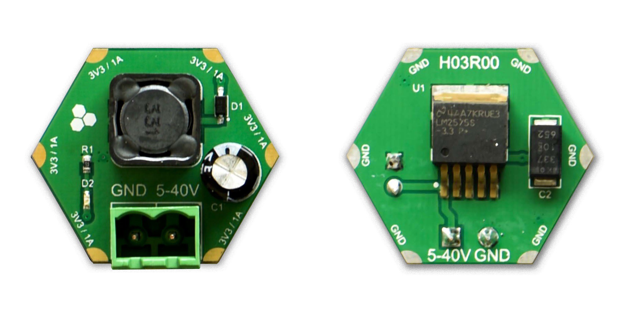
- Dust Computing: Hexabitz does not follow the traditional model of a single motherboard (controller) and 'dump' daughter boards that has been around since the advent of micro-computing. We believe computing is cheap and small enough these days that it should be embedded in each PCB. All our modules -except the very simple power sources- feature a small and low-power Cortex-M0 MCU. Future high-performance implementations will probably feature FPGAs and other logic blocks.
- The Wired-Mesh: Standard electrical buses impose topology and capacity limitations that destroy modularity. Hexabitz is based, instead, on a wired-mesh, decentralized network concept. Pioneered by wireless sensor networks, mesh connectivity provides ultimate modularity and a more scalable system. Coupled with Hexabitz nature-inspired form-factor, the wired-mesh enabled us to put a much larger number of modules together (> 5 times more than other platforms) and still keep a small footprint.
- Distributed System: A side benefit of 2 and 3 is that you get a truly parallel and distributed system. Hexabitz application development is a little bit different than standard embedded systems: you emphasize connectivity and think about your application more holistically, breaking into separate chunks that run in-parallel on separate modules.
- Stand-Alone: Since all configurable Hexabitz modules come with their own MCU, they act as stand-alone development boards that can be used without any external controllers. You can access module functionality by using the Command Line Interface (CLI) and directly connecting to a PC or triggering actions with external buttons / switches. Eliminating the need for external controllers can reduce overall system size and cost in many applications.
- Automation-Ready: The current hardware implementation of Hexabitz is the most abstract one, geared more toward production than a plug-n-play system. On top of this implementation, one can introduce multiple layers of add-ons that customize the platform for different applications (connectors, magnets, attachments, stress-relief mechanisms, etc.) One of the benefits of the abstract implementation is that arrays can be assembled automatically by pick-n-place machines and soldered by robots, providing opportunities for future automated prototyping factories or even a desktop-size prototyping machine.
Where to Start?
Read the following logs for a primer on Hexabitz hardware and software architecture. Check the gallery of photos and videos on Hackaday and on our website. Also check the FAQ section and learn about the inspiration behind Hexabitz and...
Read more »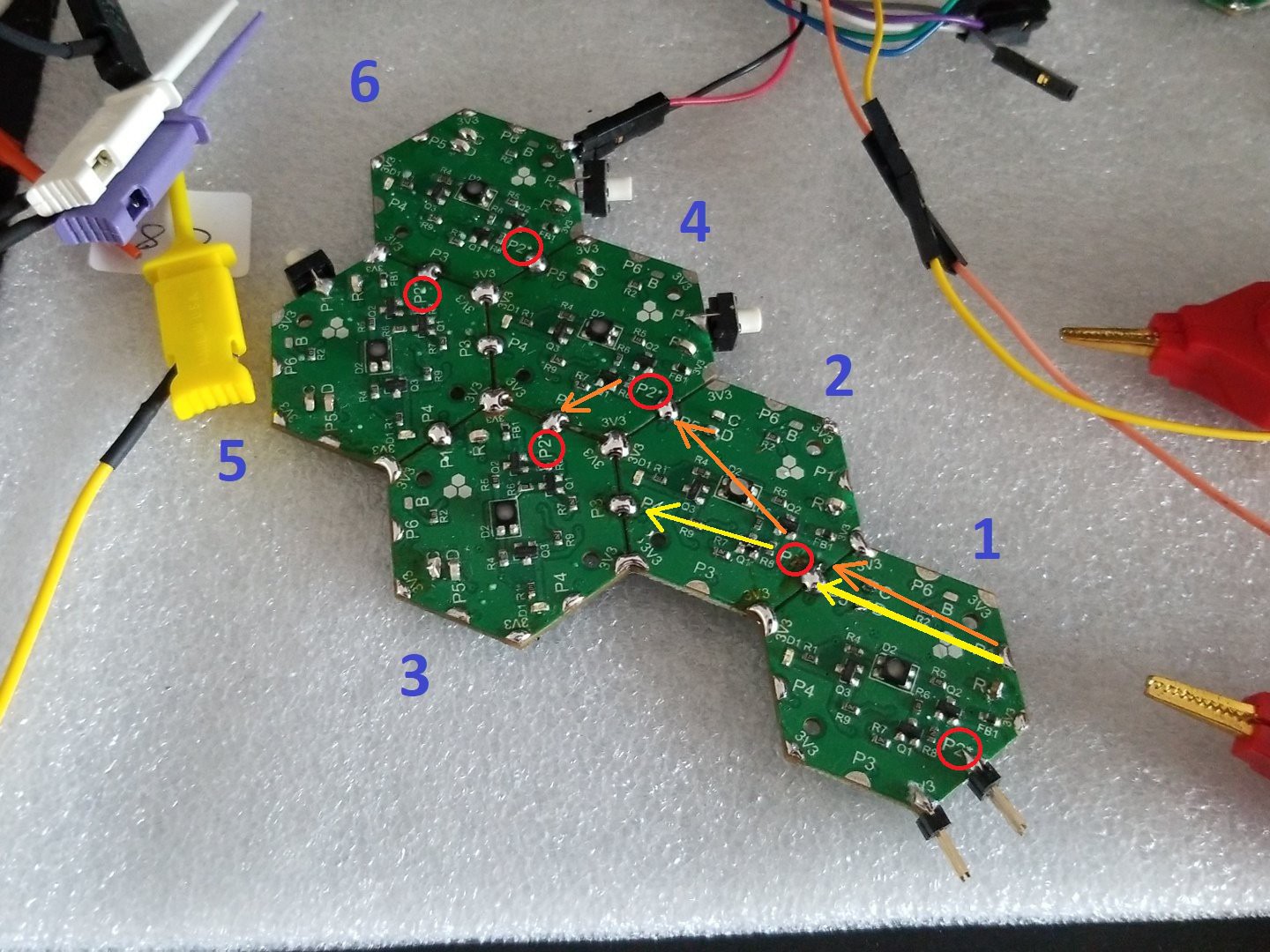


 Ruslan
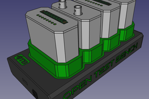
 Bastien
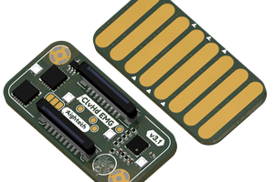
 Aightech
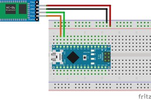
 Silícios Lab
The connectors instead of soldering are better. I already have same idea with you. But it was retired because the shape was not fit for my education job. You done well, anyway. Thanks for your share.