 Gigawatts
This all started when I tried hacking my cheapy Timex bed side clock to display 24 hour time. I looked up the datasheet for the clock chip inside and found it was capable of switching between both modes. I soldered up a switch, flipped it over to 24 mode, and tada! 24 hour mode! This worked great, until it came around to 8pm (20:00).
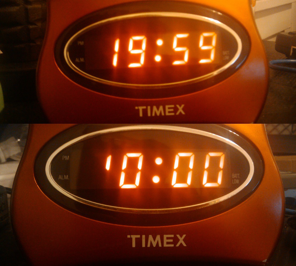
Some cost cutting engineer decided it would be a great idea to put a 7 segment in a clock which only had 2 usable segments! Seriously guys? I tore open several other cheap alarm clocks, and found this is aparently a common thing to do.
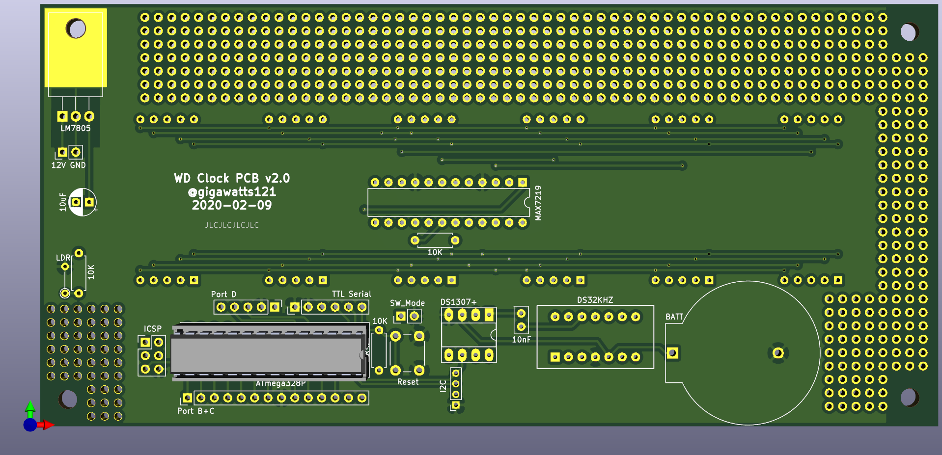
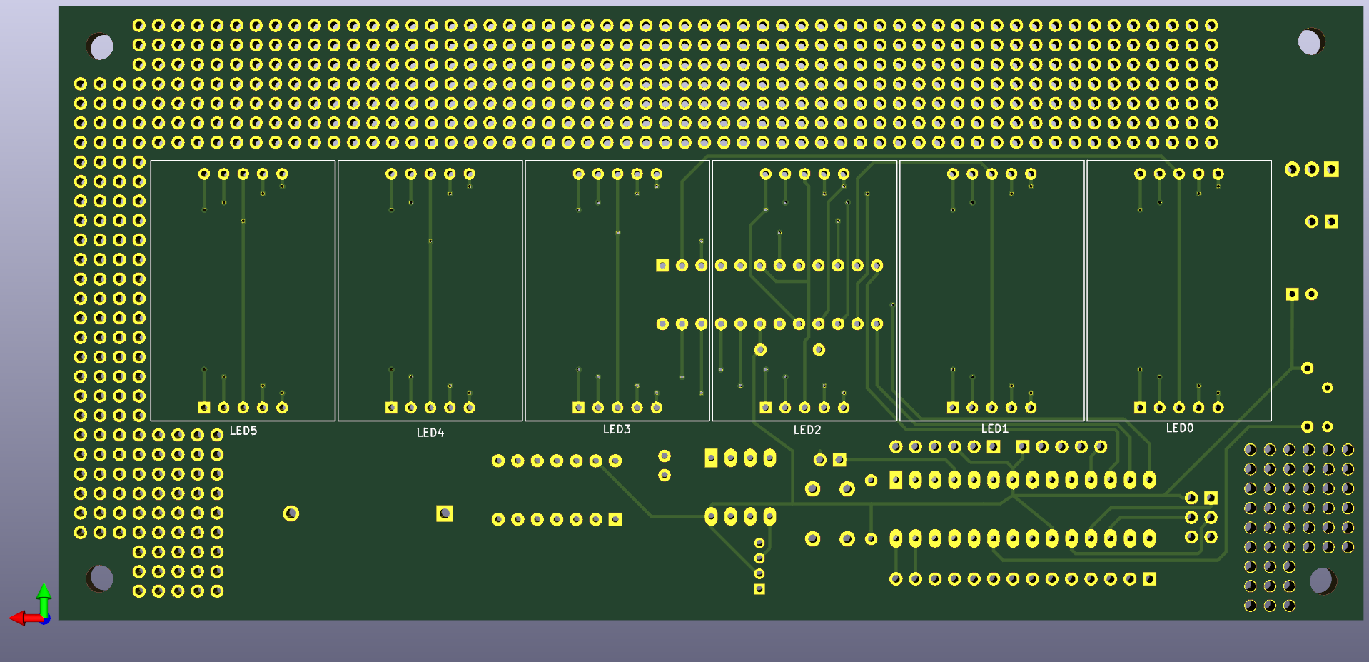
After a trip to my local American Science and Surplus, I had a pile of red 1.25" seven segment displays ready to wire up. After a prototype with an Arduino, I wired up 6 digits to a MAX7219, hand soldering jumpers between each digit. Note to self, next time use proto board with copper pads :P
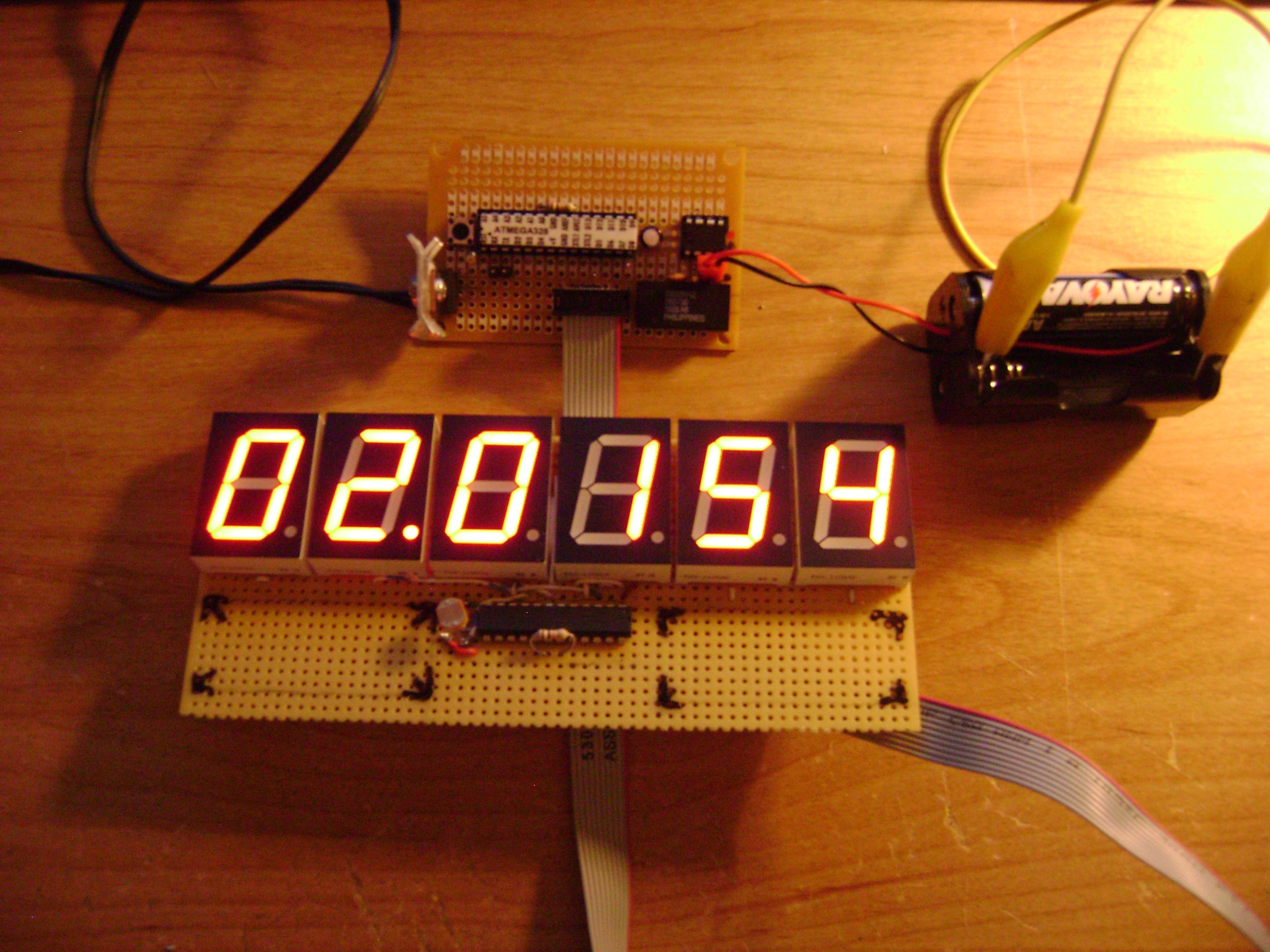
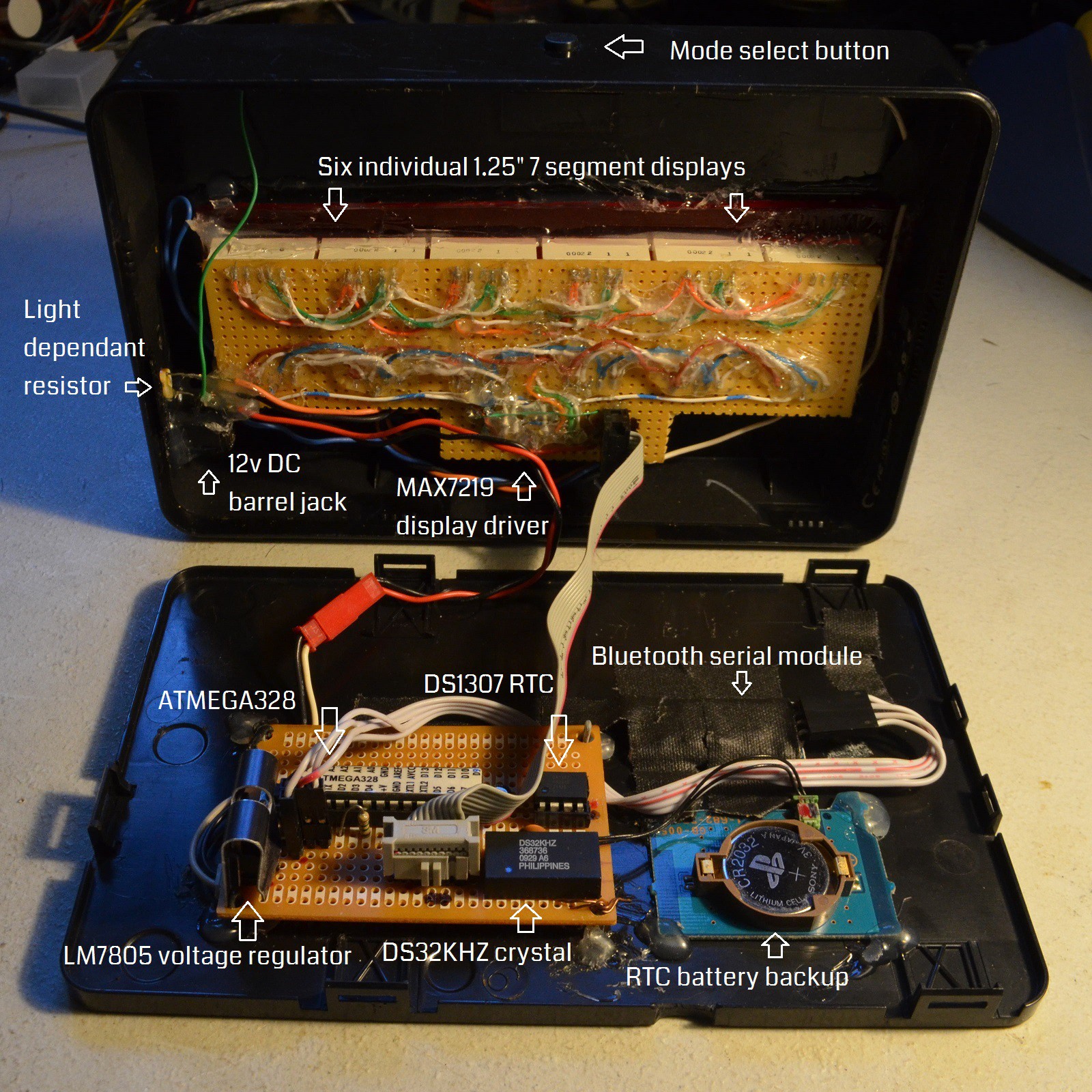
I soldered together a basic bread board version of an Arduino using an ATMEGA328. Add in a DS1307 real time clock, a DS32KHZ TCXO, a backup coin cell battery holder from a busted PlayStation 2, and a Light Dependant Resistor for dynamic dimming.
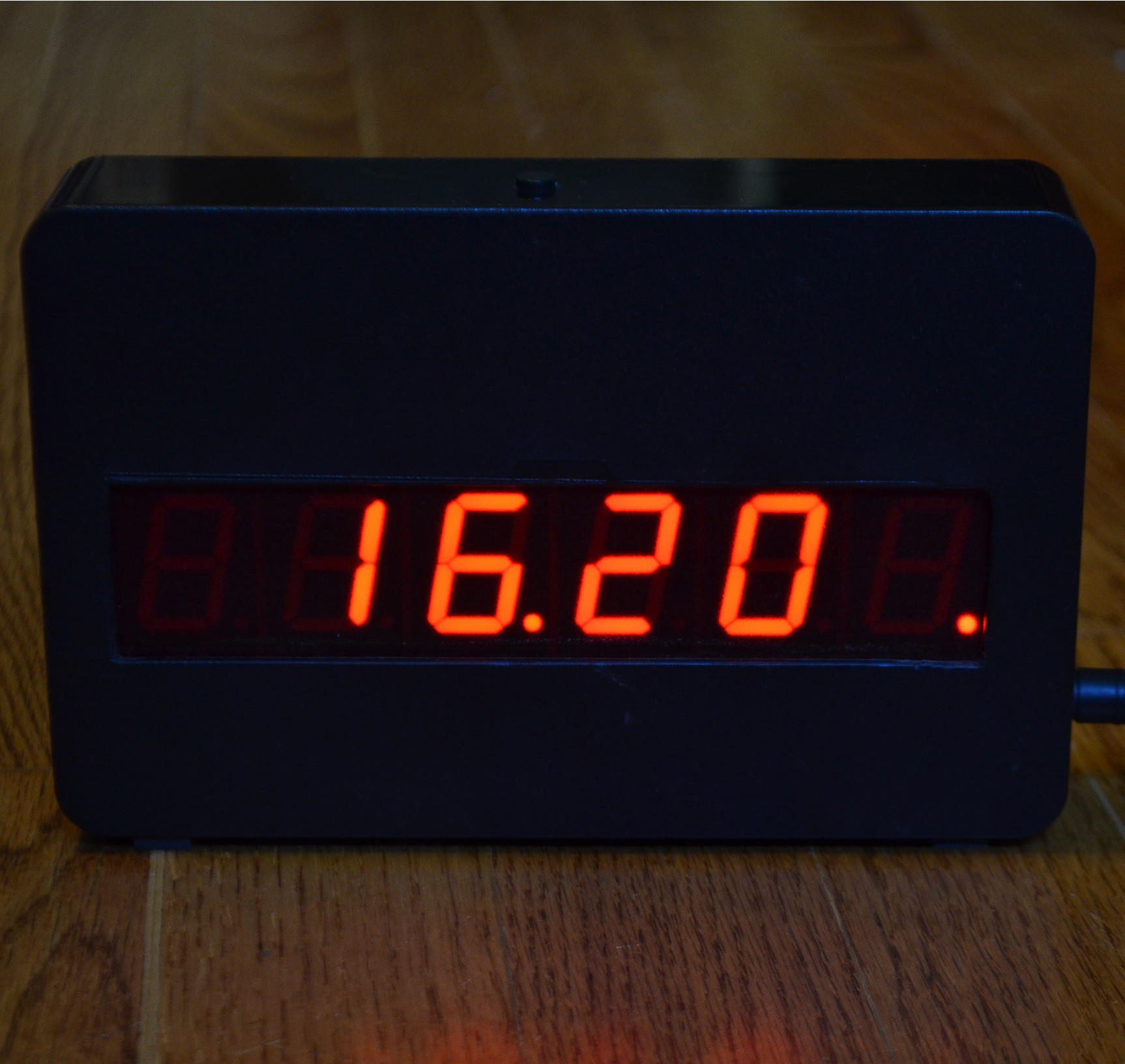
In its current state, the clock currently has 3 modes, switchable by the single tactile button on the top of the case. The first mode shows the current 24 hour time (hours and minutes only) with a blinking dot between the hours a minutes blinking on and off every second.
The second mode show the current date (day, month, year) with the dots between the day and month, and month and year alternating once per second.
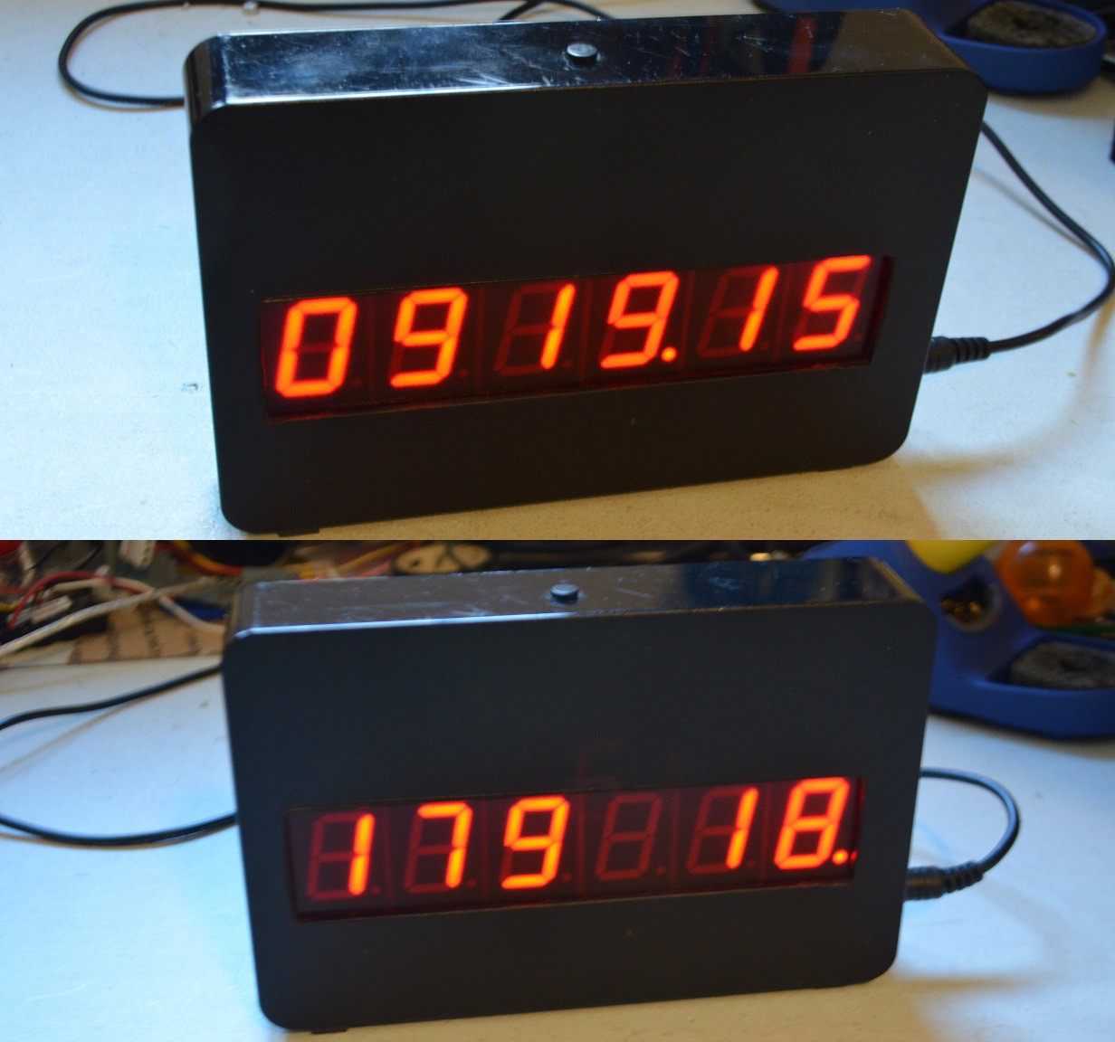
The third mode is count down clock to a user select-able date in the future (currently hard coded in the firmware). I have used this mode at the last few New Year's Eve parties I have attended/hosted, and its a big hit. When the countdown is greater than 24 hours, it displays remaining days and hours. Once below 24 hours, it counts down hours, minutes, and seconds. Once the event time has passed, it displays a message like "Happy 2015" or "Happy B-DAY".
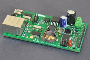
The clock also contains a cheapy bluetooth to serial module, connected directly to the ATMEGA328's hardware serial pins. This allows me to run a script on my linux server which sends the current epoch time to the clock via bluetooth serial profile, which updates the onboard RTC. I had plans to send weather information via this bluetooth serial link as well, but have yet to implement it. The decimal point on the furthest right digit lights up for a few seconds after a successful update, as seen in a few of the above pictures.
The enclosure for the clock comes from a Western Digital external hard drive. This case is ideal because it snaps apart and back together very easily. The rectangular hole in the front was cut out with a laser cutter at my local hacker space.
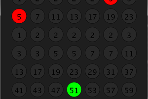
I have toyed with a few additional modes, such as displaying the current 6 digit TOTP used to access my server, and adding temperature / humidity sensors.
Projects like this are never really done, but it is "complete enough" that it makes a fantastic bed side clock that does what I need it to do.

 Dilshan Jayakody
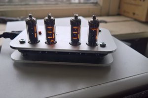
 treibair
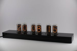
Oh! Good to hear the news that you will redo the project with ESP8266 or ESP32; Maybe I'll wait. I have several of these displays, single and double;
Thanks for the answer.