 Aaron
Aaron-
1Step 1
Selecting Hardware
Case
Searching online, I found the "Mini Macintosh", an accessory from the American Girl doll catalog that was released in 1996. This toy version originally had a 3.25" monochrome LCD display that showed static images as seen in this YouTube video. I thought it'd be perfect, so I bought one on eBay.
Computing ModuleOnce I got it in my hands, I realized that a Raspberry Pi wouldn't fit in the case unless I started de-soldering connectors, and even then it'd be a challenge. Fortunately, around this time HardKernel released their ODROID-W computing module, which is a South Korean clone of the Raspberry Pi. It got some hate from the internet, but it's still an impressive bit of engineering so I ordered one immediately. (They've apparently been discontinued since then.)
Display
The screen comes from a Chinese automotive rearview display. I had previously tried a TFT display, but the drivers for this particular one aren't well-written so it flogs the CPU at 100% whenever it's in use.
Power
Since the screen runs best at 12V but the ODROID-W only needs 5V, I bought this DC/DC step-down converter. It takes anything between 12-24V as input, and outputs 5V at the other end.
Peripherals
I also included a USB Hub, USB Wi-Fi adapter, and a wireless keyboard/trackpad. -
2Step 2
Preparing the Case
I disassembled the case and found that it consisted of three pieces: a "lower" base with the battery compartment, the "upper" shell with power switch and speaker, and the front panel with screen.
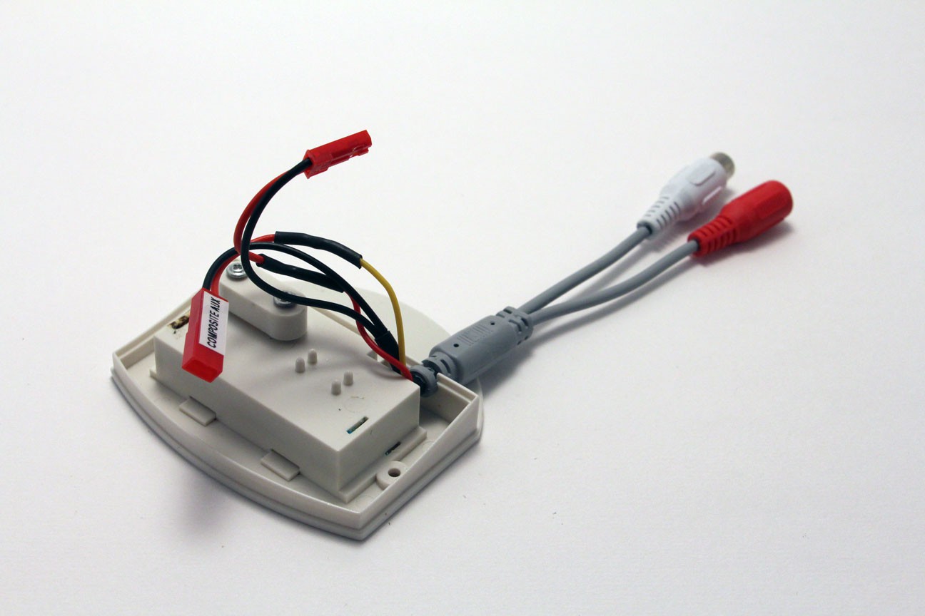
In the lower base, I slightly widened a hole where the original mouse wire entered and inserted a combination power and RCA cable. The cable was originally for a microphone, so all I had to do was cut it apart and spray it with a can of gray vinyl dye. The RCA connector will be wired to the secondary input on the display, so I can connect other composite devices as inputs to the Mac's screen.
![]()
Shown above: The lower base with power/RCA cable.
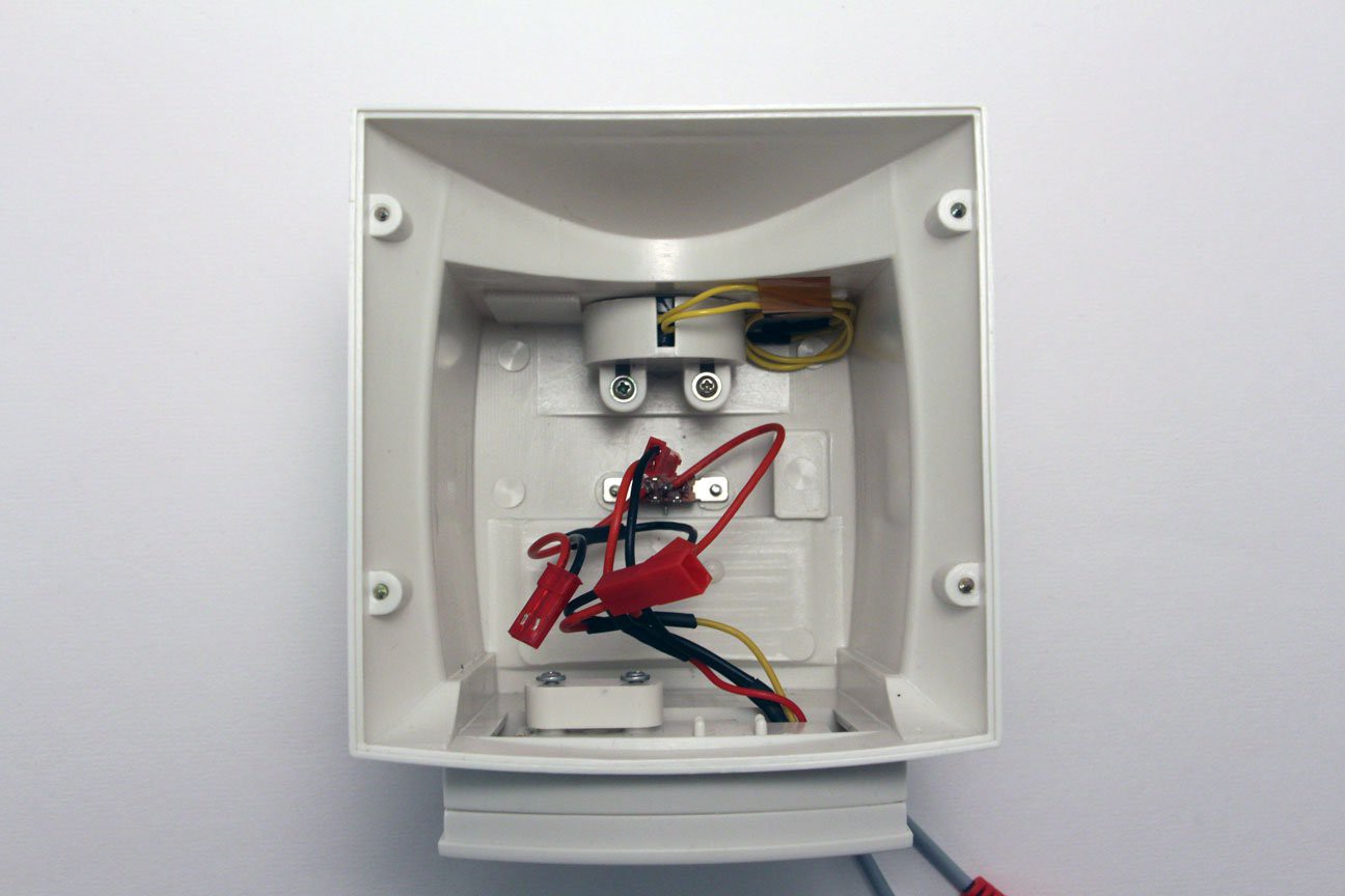
In the upper shell, I soldered JST connectors onto the power switch. The female plug is "input", while the male connector is "output", with the toggle switch operating as a simple open/close on the positive lead. There's a mono speaker (8-Ohm, 1-Watt) mounted in the top as well. I originally tried using an audio amp from Sparkfun, but the quality wasn't very good so I've removed it until I figure out an alternative. In the meantime, the wires are bundled together and secured with kapton tape.
![]()
Shown above: The upper shell with power switch and speaker.
Shown below: The lower base and upper shell shown assembled.![]()
-
3Step 3
Mounting the Internals
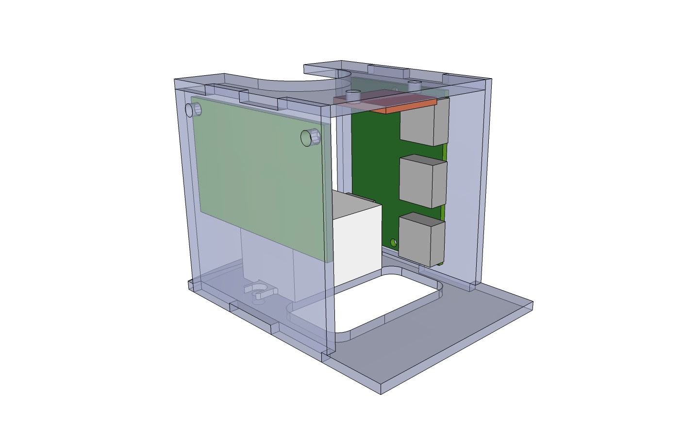
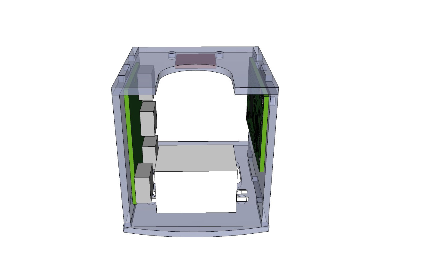
To avoid damaging the casing and to allow future expansion, I made an internal frame that would house all of the other components independently. I modeled it in Sketchup and then laser-cut the design out of 1/8" acrylic.
![]() Shown above: The internal mounting frame, as designed.
Shown above: The internal mounting frame, as designed.
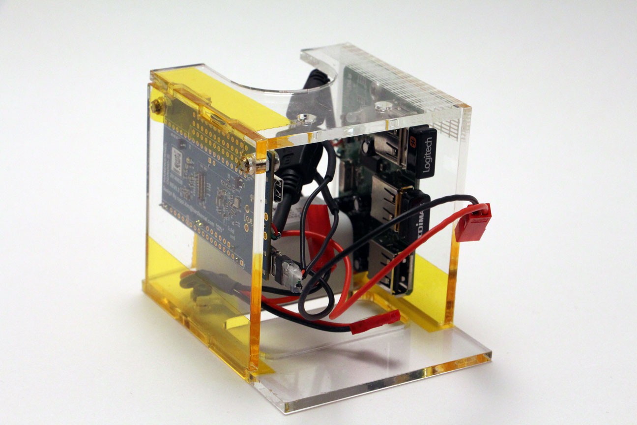
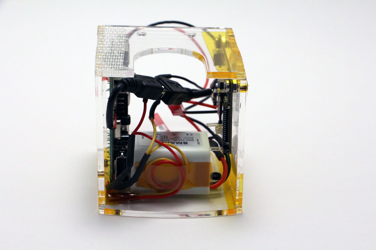
Shown below: The internal mounting frame, finished.![]() The walls of the frame are held together with tape, which seems to work well enough for stability. The ODROID-W and USB hub are mounted to the sides using screws and threaded inserts. The power converter is mounted to the floor in the same manner. The audio amp was mounted to the top using zip-ties, but I removed it prior to taking these photos. The excess 5V power wires are secured against the step-down converter with more kapton tape for future use.
The walls of the frame are held together with tape, which seems to work well enough for stability. The ODROID-W and USB hub are mounted to the sides using screws and threaded inserts. The power converter is mounted to the floor in the same manner. The audio amp was mounted to the top using zip-ties, but I removed it prior to taking these photos. The excess 5V power wires are secured against the step-down converter with more kapton tape for future use.![]() Shown above: Alternate view from the rear, as designed.
Shown above: Alternate view from the rear, as designed.
Shown below: Alternate view from the rear, finished.![]()
![]() Shown above: The frame is inserted into the assembled lower base and upper shell.
Shown above: The frame is inserted into the assembled lower base and upper shell. -
4Step 4
Mounting the Screen
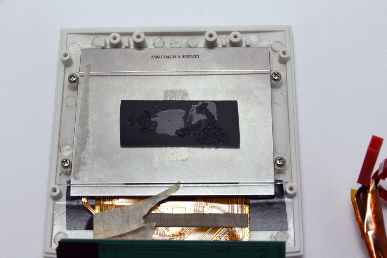
The disassembled screen fit in place almost perfectly - all I had to do shave down the sides of the screw posts by about a millimeter on each side. I added a strip of electrical tape along the bottom to prevent the backlight LED from leaking through the plastic front panel. The screen itself is mounted to a piece of acrylic using double-sided adhesive, which is held in place using the screws that originally held the clear plastic screen protector. I cut a replacement screen protector and sandwiched it in front as well.
![]()
Shown above: Screen mounted with acrylic panel and adhesive.
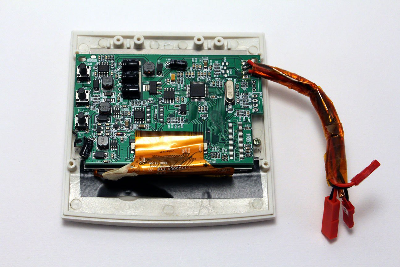
The screen's control board was originally held in place using a second piece of double-sided adhesive, but the heat from the board was causing the acrylic screen sandwich to expand and warp. Instead, I've removed the adhesive and simply allow the control board to float freely within the case. It's still a tight fit, so it doesn't really move that much. I also soldered new connectors to the control board and bundled them with tape.
![]()
Shown above: Front panel and screen, ready to attach to the assembled lower base and upper shell.
-
5Step 5
Software
Since the ODROID-W is fully compatible with all existing Raspberry Pi software packages, I performed all of the software configuration on a full-sized Raspberry Pi Model B, then removed the MicroSD card and installed it into the Mini PowerMac when I was finished.
Installing Linux
This part is pretty straight-forward. I simply downloaded NOOBS and copied it to a blank MicroSD card. (Full instructions are available on the Raspberry Pi Foundation's website.) In the NOOBS wizard, I chose to install Raspbian.
Update Package Sources
Once I had Raspbian up and running and connected to my wireless network, here are the changes I made:# sudo nano /etc/apt/sources.list # deb-src http://archive.raspbian.org/raspbian/ wheezy main contrib non-free rpi # sudo apt-get update
Uninstall Mathematica (and free up 454MB):# sudo apt-get purge wolfram-engine
Installing the Macintosh EmulatorTo install Basilisk II, I followed Derek Warren's instructions:
# sudo apt-get install git libsdl1.2-dev autoconf libgtk2.0-dev libxxf86dga-dev libxxf86vm-dev libesd0-dev
# git clone https://github.com/cebix/macemu
# cd macemu/BasiliskII/src/Unix
# aclocal ; autoconf
# autoreconf -I ./m4
# ./configure --enable-sdl-video --enable-sdl-audio --disable-vosf --disable-jit-compiler --without-gtk
# sudo make install
Installing Mac OSTo set up Basilisk II and install Mac OS 7, I followed instructions from the PiMac Arcade tumblr.
-
6Step 6
Other Tweaks
Adding a Bootsplash
Shea Silverman's blog has great instructions on how to play a video file during Raspbian's system boot. I created a video using still photos from the Mac OS boot sequence and ffmpeg on my Windows machine.
Switch from LXDE to OpenBox
Booting into LXDE is time-consuming and distracting. Since we're not really going to be using it anyway, I prefer the spartan interface of OpenBox. Switch to it with the following:# sudo update-alternatives --config x-session-managerSelect OpenBox when prompted.
Autostart Basilisk II
To configure OpenBox to automatically launch Basilisk II, I followed these instructions from the Raspberry Pi forums. Add the following line to ~/.config/openbox/autostart:BasiliskII --nogui true
Optional: Modify the Console Size
To make console text easier to read on the 3.5" screen, you can follow these instructions from the Raspberry Pi Spy blog. -
7Step 7
Thoughts & Next Steps
For future improvements, I'd make the following changes:
- Use fewer JST connectors. They seemed easy in concept, but they're really difficult to mate/un-mate, and they take up more space than I thought they would. I'd find something easier instead.
- Solder the USB hub wiring directly onto the ODROID-W. I used MicroUSB connectors here, thinking I'd want the flexibility to replace the USB hub later. In reality, it's one more connection to worry about that takes up too much space.
- Don't bother providing a secondary composite input. It sounded useful, but I haven't actually used it for anything.
- Provide a Micro HDMI output. This would probably come in handy more often: to be able to connect to a larger monitor for better readability. This might cause problems with the display settings in Basilisk II, though.
- Don't use a composite screen. It was cheap, but the low quality definitely shows. Interference on the video signal wires was an issue, and the readability isn't great. For my next build, I'll try OzzMaker's PiScreen on Tindie.
- Build a working Mini Mouse. The Mini Macintosh included one (as seen in the gallery photo), but I haven't been able to find an optical sensor small enough to fit inside it yet. I'm still working on this, so if you have any suggestions, let me know.
Thanks for reading!
Mini PowerMac
The Mini PowerMac is a 1/3 scale computer, based on the Power Macintosh 5200LC.


Discussions
Become a Hackaday.io Member
Create an account to leave a comment. Already have an account? Log In.