 Eric Hertz
UPDATE: Found some more sources, including one that explicitly mentions running HCT devices at 2V-6V. Sheesh. See the bottom.
-----------
I have no idea where, but somewhere in my projects' logs, I think, I wrote some thoughts regarding whether it would be within reason to expect 74xCT devices to run at 3.3V, like their 74xC counterparts...
Obviously, that's not within-spec (they're spec'd for 4.5-5.5V).
The point of xCT devices being to interface TTL devices' outputs to 74xC CMOS devices' inputs, when running at 5V. If you look at the input/output specs of the TTL and CMOS@5V, you'll note that:
74HC04@4.5V (why they don't specify at 5V boggles my mind):
Vih-min = 3.4V
Vil-max = 1.35V
whereas TTL:
Vih-min = 2.0V
Vil-max = 0.8V
-------
Why am I comparing Vih/Vil's rather than Vih/Vil to Voh/Vol...? Because the output-voltage parameters vary depending on the load... It's up to the designer to make sure the loading doesn't cause the output to "sag" out of range. If you designed your TTL circuit right, it's guaranteed to be able to drive a TTL input with Vih/Vil as-specified, above.
------
So, you can see, TTL's guaranteed output-voltages, when loaded, aren't in range of a 5V-CMOS input; TTL might just output 2.4V for a guaranteed high, but CMOS might just require 3.4V to be considered a guaranteed high.
-----
Alright, so they've invented the 'T' series (ACT, HCT, AHCT, whatnot, but NOT LVT, as I recall, that's different, so read them datasheets!)... They invented the 'T' series to interface TTL's outputs with CMOS's inputs (when running at 5V). The 'T' series is guaranteed to work with TTL-outputs connected to its inputs, while still being a CMOS part.
WEEE!
---------
Now, as a hacker, or maybe just "a hack," I'm looking for ways to make use of what I've got... And I've got... access to a lot more 'T'-series parts than 'C'-series... (and *significantly* more TTL/LS/A/S/F 5Volters, but that's another story).
And... now it's starting to get to the point where I'm actually using 3.3V in my experiments somewhat regularly.
----------
So, assuming the 'T' series only differs from the associated 'C' series in its *inputs*, it seems somewhat reasonable to assume they'd actually work *like* the 'C' series when run at 'C'-series voltages (except, of course, for their inputs). I can't really back up this theorizing, except to say that the 'C'-series and 'T'-series usually share the same datasheet with the only specified differences (I've noticed) being those of voltage-levels (and slightly increased propagation-delays for the T-series). So, my guess, is that they were developed pretty much alongside each other, probably using the same silicon processes, and internal circuitry, and the only difference is the input-circuitry.
--------------
Now, unlike the old old datasheets of yesteryear wherein they actually showed the BJT-equivalent circuits for TTL devices, I have yet to find MOSFET-level internal-circuits for 74-CMOS devices...
Until Now.
http://www.nxp.com/documents/user_manual/HCT_USER_GUIDE.pdf
Alright! I think we've got something to work with, here!
Definitely read the explanation in that user-guide.
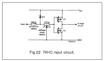
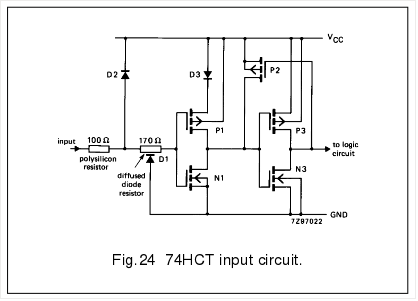
But, basically, if I understand correctly, *really simplified* what they've done is insert an inverter at the input that runs at a slightly lower-voltage than the rest of the circuit... kinda like inserting a 74HC04 running at 3.3V between your TTL-output device and your 5V-CMOS device. (This is *really* simplified). Then they threw in P2 as, essentially, a pull-up resistor.
A little less-simplified, P1 allegedly is "cut out" of the circuit, entirely, when the input-voltage is greater than something like 2.7V, which is not guaranteed by TTL, but apparently is considered expectable. The main effect being a reduced current-draw, since N1 is on.
I'm not really seeing anything in this that suggests it wouldn't run at 3.3V... The input, then, would essentially be like a 74HC04 running at 2V (value pulled randomly out of the air). So, as long as the 3.3V CMOS output connected to this input pulls *low* enough for, say, a 74HC04@2V's Vil-max, we should be set, and otherwise we don't need to worry about its Vih-min, which will surely be higher than the equivalent HC@2V's Voh-min (and since Vi-max = VCC = 3.3V)
Vil-max@2V = 0.5V
Vol-max@3.3V = only specified in the uA loads... Let's say we're driving an LED, as well...
Vol-max@4.5V/4mA = 0.26V, and should be lower for lower VCC voltages (right?)
Seems entirely reasonable to me. But I've been known to make mistakes.
(NOTE, wherever that log went, I also found a page stating that TTL circuitry starts working at around 3.6V and is considered fully functional at 4V... I've run it at 3.6V successfully, albeit with lower speed and output-expectations than specified in the datasheet.)
Oh, and... Most things I've used that specify 3.3V are actually 3.0V-3.6V... So yahknow, for hack's sake, running the entire system at 3.6 would probably make it that much more reasonable.
---------------
WHOA! Check this out (same document):
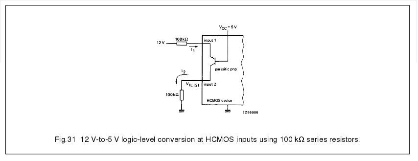
There's apparently an intrinsic PNP transistor in the input-structure, which is generally ignored, but which can be used to advantage... That's *way* beyond me, at this point, but wow!
--------------
Jesus (That's pronounced "Hey Sus") H. Christ. (That's pronounced "Christ").
Earlier today, the result finding a document I'd been lacking regarding PC-133 specifications I'd been unable to locate for five friggin' years, at the friggin' top of my search results today, as if I'd never searched for *exactly* those terms before, in the past FIVE YEARS of working on that project.
Now, "hct input circuit" (again, how could that not've been amongst *the first* searches I'd've done the last time I looked into this?!) returns not only that one document, but now a whole slew of others from other manufacturers as well.
--------
Result from document two in *today's* search results, from what I'm damned-near certain are the results from an *exactly* identical set of search terms several days ago:
"Since internal switching layout is equivalent to HC circuits (with the exception of the input stage), these components could be operated from a 2-V to 6-V range. For HCT circuits operating at less than 4.5 V, the load-level noise margin is reduced and becomes incompatible with TTL thresholds, thus losing one of the primary advantages of the HCT devices" Right.
Go @Ted Yapo you've either been darn-near quoted!
http://www.ti.com/lit/an/scla011/scla011.pdf
Got some reading to do... Here's another that might be useful and at the very least didn't show up in my last search last time...
Discussions
Become a Hackaday.io Member
Create an account to leave a comment. Already have an account? Log In.
So, with (normal-input) CMOS devices, the threshold is 1/2 the supply - so either rail could be considered the reference I guess, and that gives you maximum noise immunity. For kicks, you could run 74HC (or 74AC) devices from a negative supply. Connect the Vdd lines to 0V (this is the reference, so use a nice, solid ground plane), and connect -5V to the Vss (may be called "ground" on the data sheet) pins. Everything should behave as normal, right?
I could never understand why ECL was run with a negative supply voltage - then I read that some people use a positive supply - evidently with some reduced performance somehow.
While we're at it, where the heck did 5V come from, anyway? What's so special about that, and when did it become standard?
Are you sure? yes | no
Your idea of running a negative supply for CMOS parts sounds reasonable, especially in looking into the input-circuitry. Though, what about e.g. a NAND gate, where, internally, the circuit may be laid-out like your #CBJT Logic NANDs, with two mosfets in series, referenced to the original VSS terminal, which now lies on a (negative) rail which may vary with loading...?
(I see, now, why TTL running with a -5V supply would be gnarly! 0.4V fluctuation on our negative rail is all it'd take to screw those signals up! Sounds like your "ground plane" should still be on the -5V side. ECL, well that's a bit beyond me, still).
5V: Here's a theory: four batteries = 6V. 4.5V wouldn't work too well, since TTL starts functioning around 4V, and it wouldn't take long for those batteries to drain to that level, nevermind what we just talked about, with TTL's "High" being acceptably anywhere from 2.4V to 5V, that leaves a lot of room for error on the V+ line. So, then, why not rated for 6V? Because batteries have internal series resistance, and TTL (and old-school LEDs) takes a lot of current, so four fresh batteries would probably sag to closer to 5V when loaded that heavily. I'm pulling this all out my a**. ;)
Are you sure? yes | no
I think the NAND gate problem with a negative supply is the same as a NOR gate with the traditional positive supply - now I wonder if one or the other has better performance or noise immunity in a "normal" system?
I've looked around for the 5V story; there are some competing ideas, like it was easily derived from 6.3V filament transformers left over from the tube days, or that it's just under the reverse-breakdown voltage of the early integrated NPNs, etc. For whatever reason, it looks like it was the DTL supply, and then everything else was a matter of backward-compatibility.
Are you sure? yes | no
@Ted Yapo All these ponderings!
Your 5V story makes a lot more sense... it probably came around long before TTL, or LEDs ;)
Are you sure? yes | no
So it looks like they'll just have a lower threshold when you run them at lower supply voltages? It's possible that might reduce your noise immunity - maybe there's a way to change the threshold back to around half the supply with an external pull-up/input resistor, if you find it matters? In most cases, it probably wouldn't, I would guess.
Are you sure? yes | no
Good call on noise-immunity, especially with the AC parts and their high switching-speeds, eh? I'm not quite wrapping my head around the pull-up resistors, but series termination-resistors, or maybe the two combined to form a voltage-divider (at the input)?
Are you sure? yes | no