 Eric Hertz
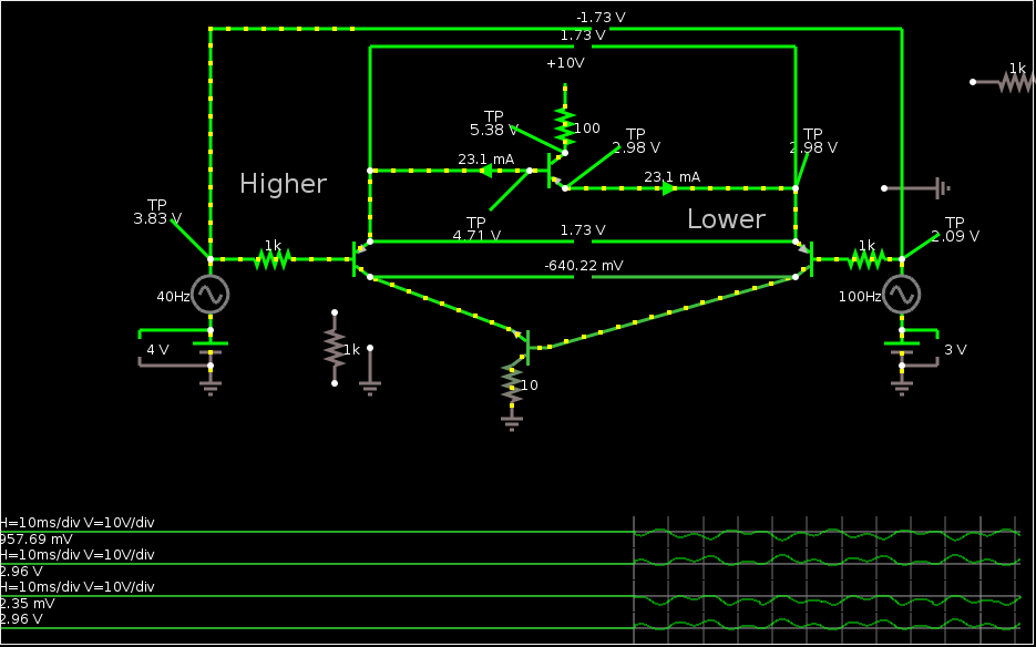
UPDATE IV: Adding an image of the differential-amplifier simulation.
UPDATE III: DEFINITELY a current-mirror. Check out the bottom.
UPDATE II: Throwing random images and notes up at https://github.com/esot-eric-test/transistorOddities
UPDATE: Isn't this a [single transistor] current-mirror? Gotta explore this in a bit more depth... Some notes at the bottom.
--------------
Split The Current, and switch it from one side.
So, imagine we have two 3V coin-cells with slightly different charges, or two solar-cells which may receive slightly different amounts of light, and want to draw darn-near twice their maximum-rated current.
Putting them directly in parallel isn't so smart, right? Especially when the system's powered-down.
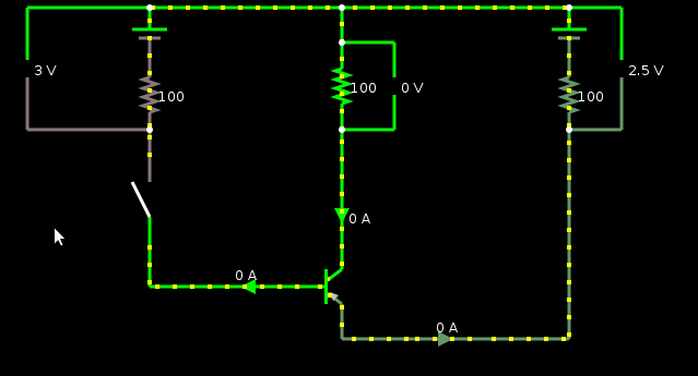
So, with this circuit--using a PNP on the ground-side, or an NPN on the positive-side, with its emitter tied to ground/positive, respectively--roughly half the current comes through each coin-cell, and the on/off switch (or maybe another normally-wired transistor?) controls them both.
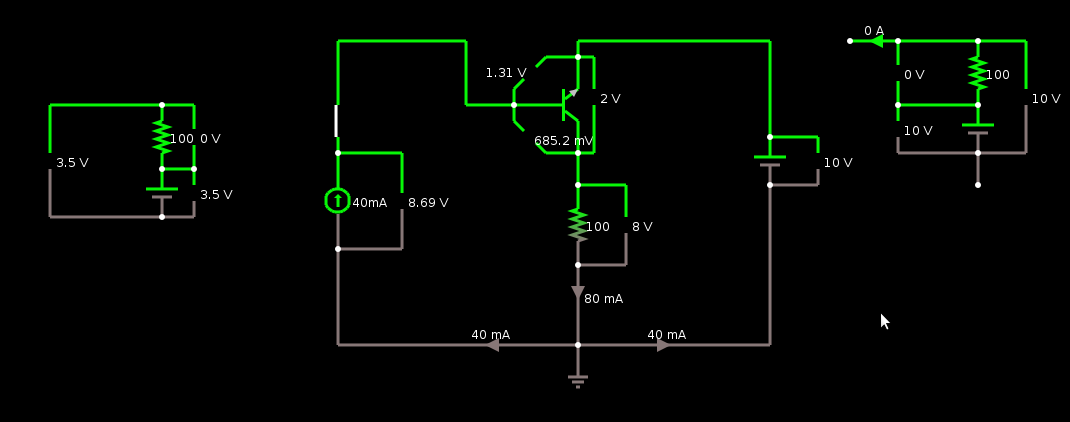
So, here I'm simulating two coin-cells; one's at 3V, and one's at 2.5V, when unloaded. But their internal series resistance is roughly 100 ohms (represented by the 100 ohm resistors on each branch).
In the middle we have a load (a circuit, LED, etc...) simulated by another 100 ohm resistor, getting about 1.5V.
The switch could be anything, maybe a "normally-wired" transistor controlled by a pushbutton and flip-flop as part of the load, etc.
Note the directions of the current entering/leaving the transistor... Current is *exitting* the PNP's emitter, and *enterring* its collector. That's why this guy's a weird setup that's been boggling my mind for weeks.
---------
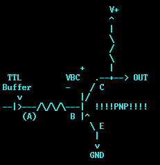
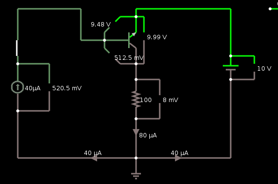
Here's the original weird circuit:
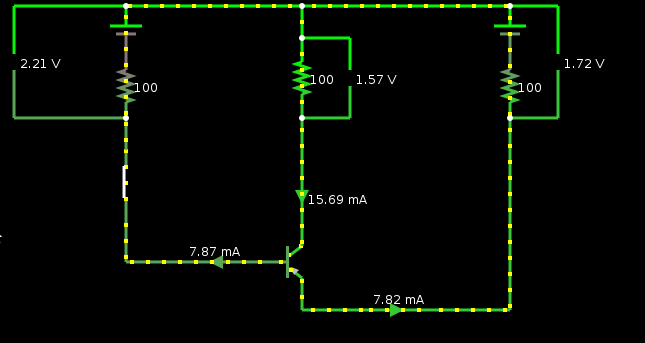
And here's another, in a more logical topology.
Note that as long as the right-side "battery" is greater-than or equal to the right-side "battery's" voltage, the two branches carry the same current. Doesn't that make it a single-transistor current-mirror? Hmmm...
-----------
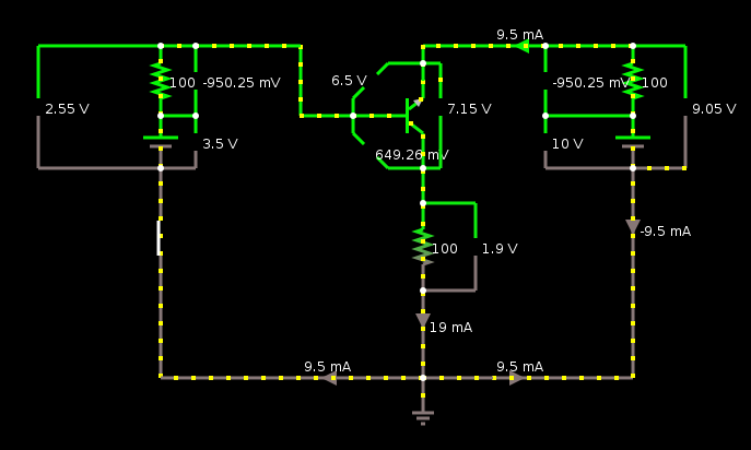
DEFINITELY a current-mirror. Have never heard of a single-transistor current-mirror, have you?
Not that we can trust simulations...
Here's a simulation of an attempt at a differential amplifier using this current mirror. It *sorta* works. Though I know little about diff-amps, these days...
-----------
If you haven't been following the saga, check out The mistake that started it all, and Some more rambling.
Discussions
Become a Hackaday.io Member
Create an account to leave a comment. Already have an account? Log In.
FYI: there exist BJTs which can handle AMPS of base-current. [!]
Recently have been trying to figure out how to power a 3A 5V circuit from a pair of 5V2A USB battery packs. This might be a way to go. I'd completely forgotten this endeavor, so opted for putting the batts in series and using a buck converter.
But I'm kinda curious about this.
Dunno if this link'll work, but it's BJTs rated for 1A or more base-current. I think I saw as high as 4A.
https://www.digikey.com/short/zpz48d
Are you sure? yes | no
Is it a current mirror because it's essentially a "forward" transistor with a beta around 1? Hmm. I'm going to have to play with this thing now...
Are you sure? yes | no
I was wondering about that... If that's the case, then it seems funny I've never heard of an NPN with a beta of 1... (symmetrical, no less) seems like there are *lots* of circuits using current-mirrors out there... Seems like a beta-1 transistor would be easy to build in silicon, especially with today's tolerances, and the tolerances required of normal current-mirrors. OTOH, the fact they use current mirrors, rather than current amplifiers seems a bit funny, since most cases all that current's being wasted down the one side.
Are you sure? yes | no
AHHH. But betas... I getcha. Real-world Beta tolerances are quite wide. Sim-models apparently throw in reverse-beta=1 because it's so often not a documented value. I was under the mistaken perspective that reverse-beta = 1 is an inherent factor of transistors, and thus biasing would not be needed in cases like this.
So, then, if I recall, biasing [and feedback] can set your circuit's effective-gain anywhere smaller than the actual beta, in which case, this circuit would be wiser-built forward-active.
Still, I've since discovered there ARE transistors which can handle AMPS through the base, so this idea could still wind-up useful for load-current-splitting.
Are you sure? yes | no
Do you know those cheap solar powered garden lamps with a single AA rechargeable battery ? I suspect they use a somewhat similar system...
That's intriguing...
Are you sure? yes | no
hmmm, I was thinking more like calculators, but you might be on to something, there
Are you sure? yes | no