Close
0%
0%

wESP32: Wired ESP32 with Ethernet and PoE

A low cost ESP32 core board with Ethernet and PoE for convenient "single cable" deployments

Public Chat
Similar projects worth following
The ESP32 is very popular among makers as the brains for various projects. Usually it is connected to the internet with WiFi, but an often overlooked feature of the ESP32 is that it also contains an Ethernet MAC. This project aims to create a hacker friendly ESP32 + Ethernet + PoE core board to make it very easy to apply the power of the ESP32 in new areas such as home automation, factory automation, smart buildings and data centers, where the use PoE provides major advantages in installation and maintenance.

Due to the high power consumption of WiFi, most ESP32 based systems already require wired power. Since you already need a wire, why not provide power and connectivity through a single wire and bypass deployment hassles associated with WiFi credentials and RF performance in hard-to-reach locations?

Plus the high power available with PoE makes it possible to not only make ESP32 based sensor nodes, but to create smart network-connected actuators as well!

I just completed an application-specific ESP32 based PoE board for a customer, and it got me thinking: how much interest would there be in a generic ESP32 PoE core board?

By using PoE, a single cable provides power as well as connectivity, easing deployment headaches for large installations.  PoE can provide up to 12.95 W to a load while PoE+ specifies up to 25.50 W.  Plenty for an ESP32 which takes only a watt or so, making it possible to power other loads.  PoE capable network switches and injectors are also becoming quite common and have come down in price as well.

The nice thing about the ESP32 is that it's low cost and powerful, and provides WiFi and Bluetooth in addition to Ethernet.  So even if a deployment would be mostly Ethernet and PoE based, it would still be possible to connect a node with WiFi powered from another source if necessary.  Or it could be set up as an access point for other WiFi or Bluetooth LE based sensors.

While it would be nice to support as much power as possible, previous experience has taught me that high power opens all sorts of cans of worms related to heat dissipation and EMI.  So it seems prudent to not start at the highest power levels possible.  Some potential users also showed interest in compact, very low power systems, but there are plenty who were excited about the idea of having a decent amount of power available.  So I decided to take the middle road and do a 12.95W PoE class 3 design to start with.

The ability to use local power instead of PoE is a nice feature, but also adds complexity and cost.  The problem is that PoE uses 48V nominal to reduce wiring losses, but commonly available wall warts use lower voltages for safety.  Supporting both would require the circuit to support for a wide input voltage range making things more complex.

So I settled for the following solutions: local power can provided either by adding a PoE injector, or through the (optional) USB port.  Of course, from the USB port, only 5V will be available.

Talking about the USB port, several potential users expressed the opinion to not burden every board with something that would likely only be used during once during programming and never again after that.  I agree, so I made the USB programming/terminal port an optional module.

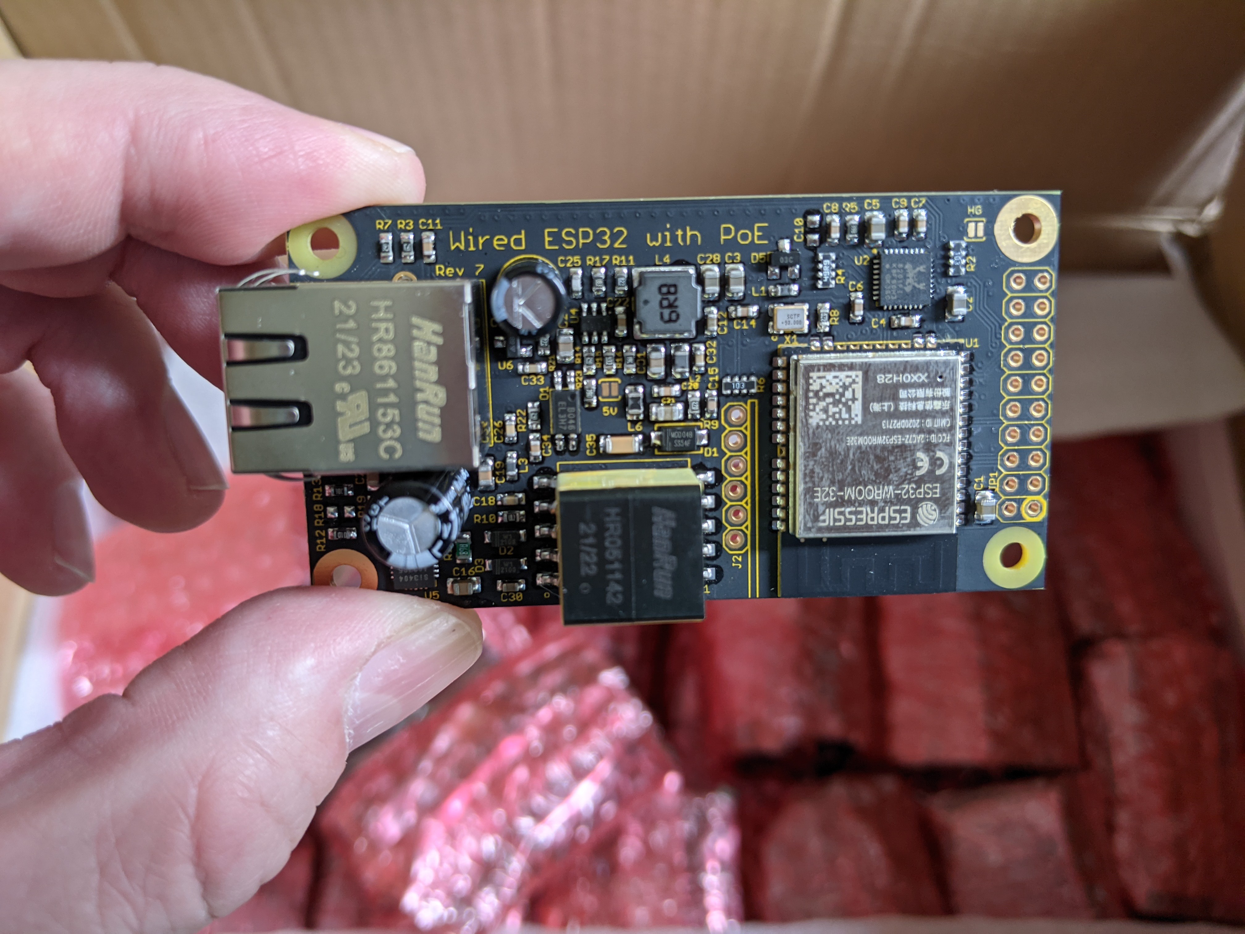
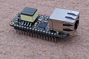
Other than those concerns, I want this module to be fully isolated (to prevent issues with long cabling), full featured (Ethernet, WiFi, Bluetooth LE, many ESP32 pins exposed), low cost and small.

wESP32-7-CCBYSA.pdf

Schematic of wESP32 rev 7 with RTL8201 Ethernet PHY

Adobe Portable Document Format - 43.26 kB - 01/14/2022 at 18:15

Preview
Download

wESP32-3-mechanical.pdf

Mechanical drawing of the wESP32 rev 3

Adobe Portable Document Format - 88.38 kB - 01/07/2020 at 16:37

Preview
Download

wESP32-Prog-1-Eagle.zip

Eagle CAD source files of the wESP32-Prog programming submodule

Zip Archive - 50.43 kB - 10/07/2019 at 14:41

Download

wESP32-Prog-1.pdf

Schematic of wESP32-Prog programming submodule

Adobe Portable Document Format - 19.49 kB - 10/07/2019 at 14:41

Preview
Download

wESP32-3.pdf

Schematic of wESP32 rev 3 with PMS150C to manage PHY reset

Adobe Portable Document Format - 43.55 kB - 03/19/2019 at 23:10

Preview
Download

View all 11 files

  • Revision 7 is available for sale!

    Patrick Van Oosterwijck09/30/2021 at 16:10 1 comment

    A little late posting here, but just a heads-up that revision 7 has arrived and is making its way to various distribution channels!

    New 4-layer PCB, much more decoupling capacitance on-board, RTL8201FI Ethernet Phy and now 16 MB of flash!

    Tindie: https://www.tindie.com/products/silicognition/wesp32/

    Mouser: https://www.mouser.com/ProductDetail/Silicognition/CS-WESP-04?qs=sGAEpiMZZMu3sxpa5v1qrriU3DaWTQdbHa4MxnML6FE%3D

    Amazon: https://www.amazon.com/Silicognition-wESP32-Isolated-Ethernet-802-3at/dp/B084RV91NQ/

    Note that the lead time shown on Mouser is bogus, they had 100 units shipped to them already.  Should ship much sooner than the lead time indicates.

  • Documentation update

    Patrick Van Oosterwijck09/13/2021 at 17:59 0 comments

    A quick heads-up that I finally found the time to update the wESP32.com website with new information related to the changes in revision 7 such as 16 MB of flash and RTL8201 Ethernet PHY.  The product brief has also been updated, make sure to check the code examples to see the changes you may need to make to your software for this revision!

  • Kingtop finished production

    Patrick Van Oosterwijck09/09/2021 at 16:30 0 comments

    A quick progress report.  MicroPython 1.17 dropped on September 2 2021 which meant that I finally had an officially released binary with support for the new wESP32 with 16 MB flash.

    To remove the biggest bottleneck in production called "me" from the equation as much as possible, I had my CM Kingtop build a fixture so they could program and test them, instead of me still having to do that with every board.  They built a nice fixture:

    Much better looking than my fixture hacked together from two perf boards. ;)  That worked, but hurt your hand when running too many boards.  Big improvement.

    Kingtop finished populating the through-hole parts and programmed and tested all boards:

    They reported two boards that failed on initial test, but they were able to correct the problem.  So an initial failure rate of 0.2%, and 0% after rework, that speaks very well to their build quality and processes.  Believe me, I've seen much much worse!

    They are ready to ship them now and it's still looking good for getting stock mid-September.

    Now I only have to harass Mouser some more to try and get them to send me a PO for the new part numbers generated for this revision, after begging for months already.  But why do something ahead of time when you can do it when it's too late, right? 🙄

  • Revision 7 production progress

    Patrick Van Oosterwijck08/20/2021 at 22:00 1 comment

    After waiting for four months since I ordered them, Mouser finally shipped the SI3404A PoE chip to my CM, so they have started production.  I received this picture of the new PCBs:

    Looking good.  I think there shouldn't be confusion about which PHY this uses, since I have it in pretty big letters on the bottom.  Last night, I received this picture with surface mount components mounted:

    Nice progress!  You can see the new RTL8201FI Ethernet PHYs and the ESP32-WROOM-32E module with 16 MB of flash.

    Meanwhile, I have also managed to get a custom board config merged into upstream MicroPython so you can actually make use of all that flash memory!  Up till now, I used the generic ESP32 images but they are made to use only 4 MB of flash.  The flash memory will be partitioned with two nice 2.4 MB OTA partitions so we should be safe for a while as MicroPython keeps growing, and a nice 11 MB of flash will be available for the MicroPython file system!  I'm hoping that version 1.17 will be released soon so I can give an official release to my CM to program in to the boards.  As usual, the boards will also come with a custom boot.py file that will set up the LAN for you.  So if you use the built-in MicroPython, the change to a different PHY chip will be completely transparent.

    I also ran some more performance testing and compared performance of the old LAN7820AI with the new RTL8201FI using the latest IDF's ethernet iperf example.  It looks like the LAN8720AI is marginally faster with UDP, while the RTL8201FI is marginally faster with TCP.  Overall, performance seems to be just fine.  The following numbers are approximate:

    LAN8720AIRTL8201FI
    iperf UDP ESP32 serving
    88 Mbit/s
    83 Mbit/s
    iperf UDP ESP32 client
    61 Mbit/s
    60 Mbit/s
    iperf TCP ESP32 serving
    23 Mbit/s
    25 Mbit/s
    iperf TCP ESP32 client
    27 Mbit/s
    30 Mbit/s

  • Bye bye LAN8720AI, hello RTL8201FI

    Patrick Van Oosterwijck05/27/2021 at 22:49 3 comments

    It had come to my attention that some customers had problems that some of their boards would stop working.  When they returned them and I did a postmortem, it was always the LAN8720AI Ethernet PHY that had died.

    Eventually I was able to recreate a setup that would reliably kill the LAN8720AI.  If I had a wESP32 connected to a particular PoE switch, with the USB programmer connected to a particular laptop, the chip would die when plugging in the Ethernet jack.  So I set out to try and determine root cause and find a solution.

    Doing some measurements on what exactly happened when plugging in the Ethernet using a battery powered oscilloscope, I could see some spikes occur on the 3.3V supply and ground when the cable was plugged in.  My theory was that maybe the charges on the various EMI caps connecting primary to secondary in the PoE switch power supply, the laptop power supply and the wESP32 would redistribute on connection and cause ground bounce that would for a very short time expose the LAN8720AI to out of spec voltages.

    Now doing these kinds of measurements, you're never really sure about what you're seeing, what's real and what's just a measurement artifact.  So I wasn't really sure, but it was something to go after.  I would try to improve supply filtering, add TVSes for ESD protection on the supply and signal pairs, and add filtering in the ground connection between the EMI cap and the circuit ground.

    I first changed supply filter caps on an existing board.  I tried larger bulk caps, and smaller close-to-the-pin caps for better response to high frequency spikes.  Didn't help.  I ordered TVSes, and added one to the 3.3V supply and filtered analog PHY supply.  No difference.

    I decided to create a new, 4-layer board layout with footprint for ESD protection on the Ethernet differential pairs, the supply, and a differential filter that would including filtering ground spikes that might be coming through the PoE supply's EMI cap.  I went to 4-layer with a 3.3V power plane adjacent to GND through 0.1 mm prepreg to provide improved HF power supply filtering.

    Here's the prototype:

    Here's the ESD protection chip I added to the data pairs, the little chip above the wasp:

    Aaaaand it didn't help squat. 😠  The PHY died just the same as before.

    Now what?  Stock was running low, and I really would rather not make another 1000 potentially troublesome boards that might die in some setups.  My goal is for the wESP32 to be powerful and reliable, able to take whatever you can throw at it.  Dying when connected to certain equipment just won't do.  I've only had a few customers complain about it, usually in some situation where there's external power, so it doesn't seem to be a widespread problem.  But still, I don't find it acceptable.

    I did some investigating, and found that in the years since the wESP32 was first released, the ESP-IDF has come to support more PHY chips.  It looks like IDF 4.x added more options, and the ESP32 Arduino core also already supports them.  In the mean time, MicroPython has dropped the IDF 3.x based images that supported Ethernet, but support may be coming in the IDF 4.x based images.  So, this opened possibilities.  IDF, Arduino and MicroPython support are the most important for me, other software is likely to follow as it gets migrated from IDF 3.x to IDF 4.x.

    I had tried to avoid changing PHY chips because I don't like forcing customers to have to change their software.  It's only a change in the PHY definition, so it's minimal effort, but it's still a change that needs to be made.  I had considered it a last resort, but after all this effort and killing tons of chips while testing, I had to finally admit defeat in my efforts to stop the LAN8720AI from dying.  I had really tried hard, tried everything I could think of to protect the chip, to no avail.

    So I set out to create a prototype with the RTL8201FI...

    Read more »

  • Second production run

    Patrick Van Oosterwijck05/10/2019 at 18:36 4 comments

    "Silicognition" PMS150C-559

    As mentioned in the last update, I ordered factory programmed Padauk PMS150C-U06 chips from Sino-Mos to provide a reliable reset for the PHY chip on every board.

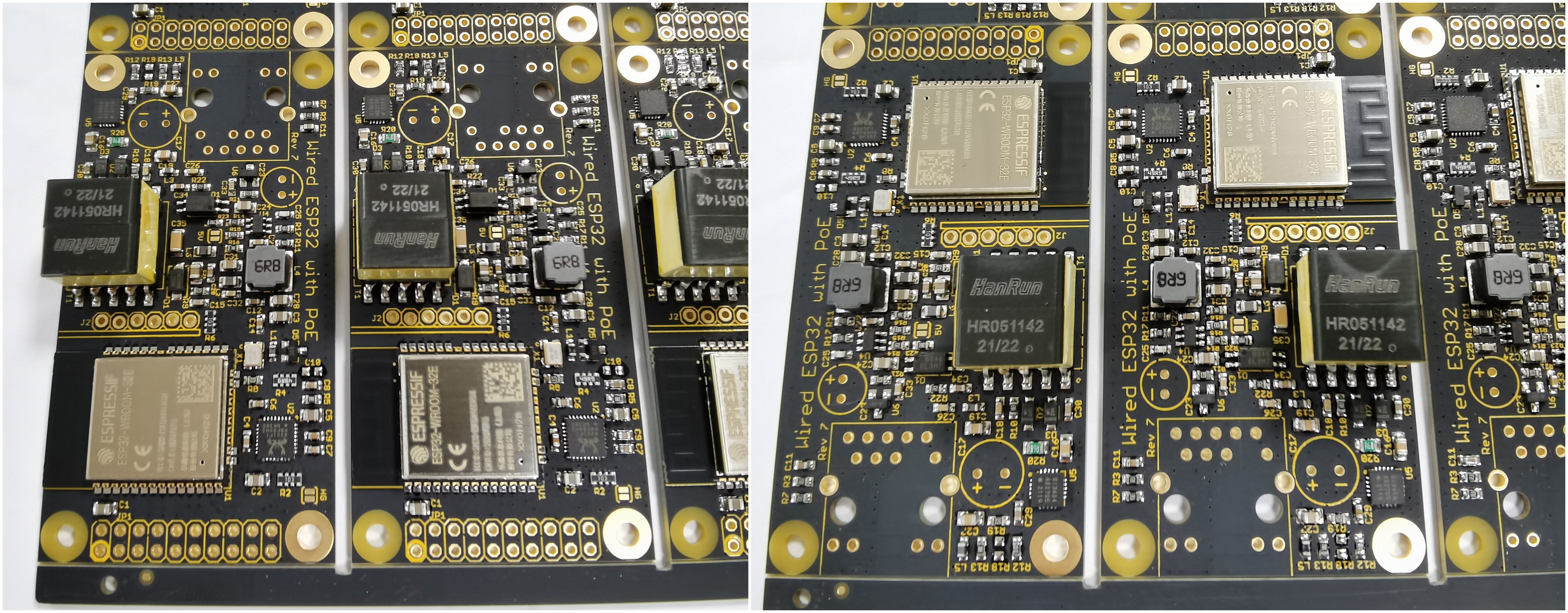
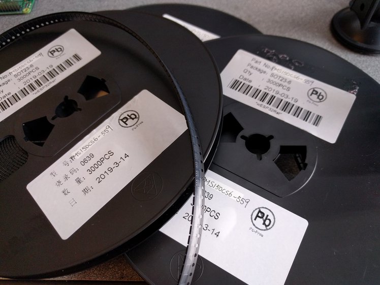
    I expected everything to be OK with them, but you never know 100% for sure if everything was understood correctly when dealing with China, until you actually have something in-hand. For one thing, I was relieved that they had indeed re-reeled them. It would have been a big bummer if I would have received a bag of loose SOT-23’s. :)

    Then I had to make sure they were indeed programmed. So I reworked another 12 boards from the first batch that didn’t initialize the PHY correctly with chips from one of these reels, and after rework they all work flawlessly!

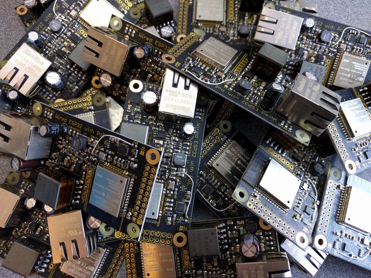
    Getting these chips has actually been a smoother experience than I had expected. It’s kind of cool to now have a low-cost custom chip that does exactly what I want it to do, with its own partnumber and everything. PMS150C-559 is now forever an “ESP32 Ethernet PHY reset manager”. Maybe I should write a datasheet for it. :)

    Also, since I have 9,000 of them, I can definitely spare some if anyone is making their own ESP32 board with Ethernet and wants a canned solution to deal with the LAN8720A PHY reset. There’s an updated schematic that shows how the chip is used on the new wESP32 revision. So get in touch if you want to buy some.

    Rev 3 PCBs

    I took a little risk and ordered new PCB panels that use the PMS150C-559 before I had verified the factory programmed chips. But it had all been taking much longer than expected already and some backers have been wondering when they’d receive their reward, so I tried to recoup some time that way.

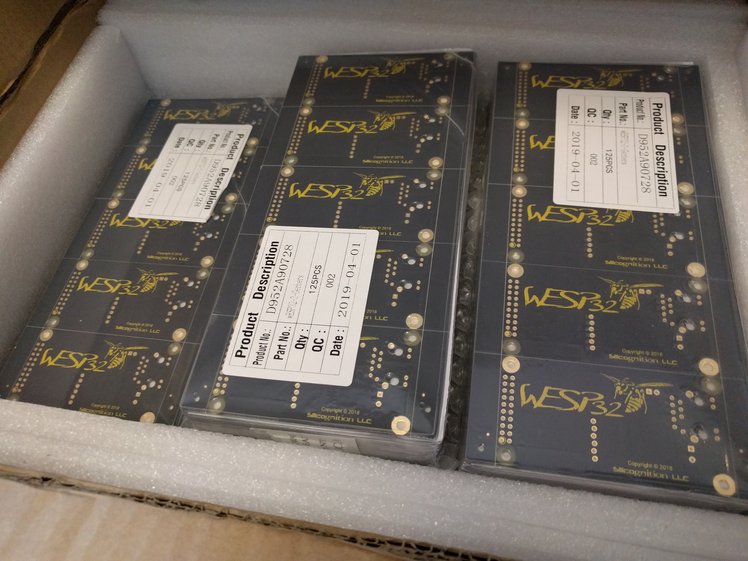
    Having everything in-house I made a kit to send to a CM I was going to try in Mexico.  That's when things started to go really sideways.

    The scourge that is customs

    The first customs issue I ran into: how to do the paperwork correctly. This was going into Mexico temporarily just to have it assembled and then it was coming right back to the US. I sought advice from the CM and a local export company, and yes, I received information on some generalities, but no one really gave me any concrete answers on what codes to use, exemptions to claim or checkboxes to tick. So after wasting almost a week waiting for guidance I gave up and shipped the box with the documentation as good as I could figure it. I marked the shipment with the AES 30.37(q) to indicate a temporary export that would be returned within a year. Whether that is correct or not I don’t know. Nobody had told me what to do and it seemed the right thing to do.

    DHL got the box to Mexico after 4 days or so. Then the trouble started. First they claimed they couldn’t contact the CM at the telephone number I had been given and had put on the forms. They wouldn’t tell me why they needed to contact them. DHL was giving me options like “we can send your package back, or send it somewhere else for an extra charge, or we can destroy it for you (!)”. This nonsense took a week or so, a week of anxious freaking out for me. Then after wasting what they must have deemed sufficient time, they somehow did manage to get in touch with them and supposedly needed a tax ID from me. I run a passthrough LLC and certainly wasn’t going to give them my SSN! That sort of blew over after some work done by the CM and then they found that the contents of the box didn’t match the PI I had included. This was partially my fault: I had based the PI on the BOM, but even though neither me nor the CM cares about the exact part number of a reel of resistors, of course customs paper pushers do. I also had included some full and partial reels in the kit and amounts on the PI didn’t match. I really didn’t think anyone cared just how many parts were left on a partial reel, but of course they did.

    What a joke. None of it should have mattered of course. The parts are temporarily...

    Read more »

  • The PHY reset saga

    Patrick Van Oosterwijck03/11/2019 at 16:09 4 comments

    Finally, a long overdue update! The silence doesn’t mean we’ve been taking it easy, on the contrary: we’ve been hard at work to make the wESP32 even better!

    A yield problem

    After the initial build of 245 units, we were able to ship 205 units that were good right away. There were various issues with the remaining 40, but the vast majority of them had the same problem: the Ethernet PHY would not get initialized properly.

    The LAN8720A Ethernet PHY is kind of a difficult part. It has several pins that have double use: during reset their logic level indicates various configuration settings, while after reset they are used in the RMII interface to communicate with the ESP32. An extra difficulty is that the chip expects the 50 MHz clock to be present during reset, so the chip can clock in these configuration settings.

    Unfortunately, the ESP32 by default uses the IO0 pin for the Ethernet MAC clock. (More options have become available for dealing with the Ethernet MAC and PHY clocks, but because IO0 was the first option available in the SDK, it enjoys the broadest firmware support so that’s why I keep using it. Plus to keep as many other ESP32 pins as possible available to the user!) The ESP32 IO0 pin is kind of a difficult pin as well, since it is used on reset to determine whether the ESP32 should go into programming mode or run the current firmware. So we have a perfect storm of an IO0 pin that needs to be high at boot to run normally, but low at boot to go into programming mode, and needs to have the 50 MHz clock on it after boot to allow Ethernet communication, and that before the PHY comes out of reset.

    When I designed the wESP32, I just looked at how Olimex dealt with the IO0, ESP32 reset and PHY reset on their ESP32-GATEWAY and copied that for the wESP32, figuring they must already have found a good solution since this was a product in production. On my first hand-built prototypes, it all worked well, so I went ahead with it in production. Then I found that more than 10% of the boards had an issue. Interestingly, in their latest revisions, Olimex has changed their product to use IO17 as PHY clock output to bypass the whole problem! This might be a smart thing to do, but I am loath to make backwards incompatible changes and take a precious GPIO pin away from the user. So I started looking at other ways to deal with this.

    Looking for a solution

    I needed a solution that would act as a reset manager for the 50 MHz oscillator and Ethernet PHY and would be triggered by the EN signal to the ESP32. When EN is low on power-up and when triggered by a programmer, the 50 MHz oscillator needs to be off, so the programmer can drive the IO0 pin low to enter programming mode, or the IO0 can stay pulled high and the system boots. The PHY needs to be kept in reset as well, because its reset can only be released after the 50 MHz clock has started up. After the ESP32 has had the opportunity to determine the boot state, the 50 MHz clock needs to be turned on, and only after the clock signal is present can the PHY reset be released.

    I had assumed there would be plenty of low cost, SOT packaged voltage detectors and reset managers that could replace my existing solution in the space I had available, but to my great surprise, nothing I could find in the market really seemed to fit the bill. There are plenty of supervisors that monitor multiple voltages and generate a reset, but I couldn’t find any low cost options that monitor one input and generate two reset signals with separate delays.

    So I started thinking outside the box: did I really need to add a little microcontroller to do this? There are several microcontrollers that are cheaper than higher end supervisor chips, and it would give me full flexibility to generate the reset signals exactly how I wanted them. On the other hand, I didn’t really want to deal with programming this micro on every board. I would need to add programming pads and a manufacturing...

    Read more »

  • Don't blow up your Ethernet phy!

    Patrick Van Oosterwijck01/16/2019 at 16:29 0 comments

    You may have noticed a warning at the bottom of the MongooseOS demo in the demo code repo, about accidentally blowing up the Ethernet phy while playing with MongooseOS demo code.

    I didn’t find any time to pursue this further, but I have to give the people at MongooseOS credit for getting to the bottom of this! I received this message from them:

    We did some research, and found the problem with ethernet. It happened to be quite stupid: the default config for the built-in LED used pin 22, which conflicts with the ethernet TX.
    So, this command should set the board correctly:
    mos flash esp32
    mos config-set eth.enable=true eth.mdc_gpio=16 eth.mdio_gpio=17 board.led1.pin=-1 board.btn1.pin=-1

    This highlights an issue that can happen with other firmwares as well: misconfigured pins doing damage to the phy. By default, the wESP32 ships with MicroPython installed and it is configured correctly out-of-the-box for the Ethernet phy as it is configured on the wESP32. If you load different firmware though, it is your responsibility to ensure the ESP32 pins are configured correctly and will for instance not configure an ESP32 pin as an output that connects to a phy output, and thus cause a short. Please refer to the schematic to make sure. The wESP32 website section on Software provides more information on wESP32 support in different environments.

    If you have ordered one or more wESP32's, I recommend you try it with the default MicroPython firmware when you first receive it, to confirm the hardware is sound and it receives an IP address (check with lan.ifconfig()) from DHCP over Ethernet, which only happens if the phy is working. All units are tested to do this before they are shipped, but this way you can prove to yourself the hardware is OK and nothing bad happened during shipping. After that you are free to use whatever firmware you want of course, but I will not replace defective units once they have been flashed with different firmware, as I cannot know what happened to them.  Thanks for understanding!

  • We are shipping

    Patrick Van Oosterwijck01/16/2019 at 16:24 0 comments

    On Monday 1/7, we finally received completed panels from Colorado Tech Shop!

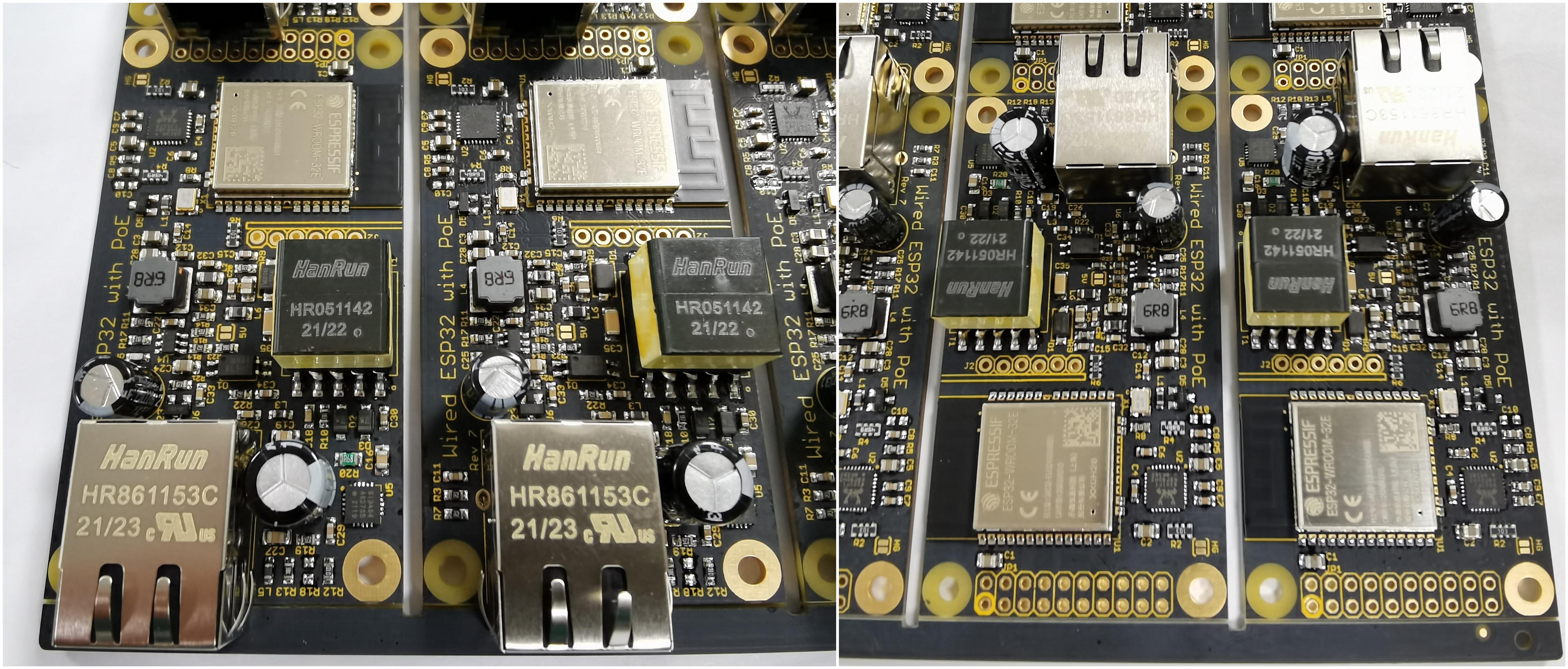
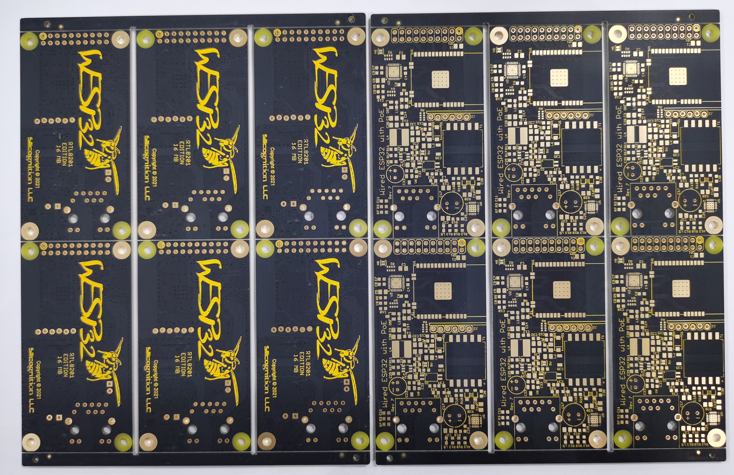
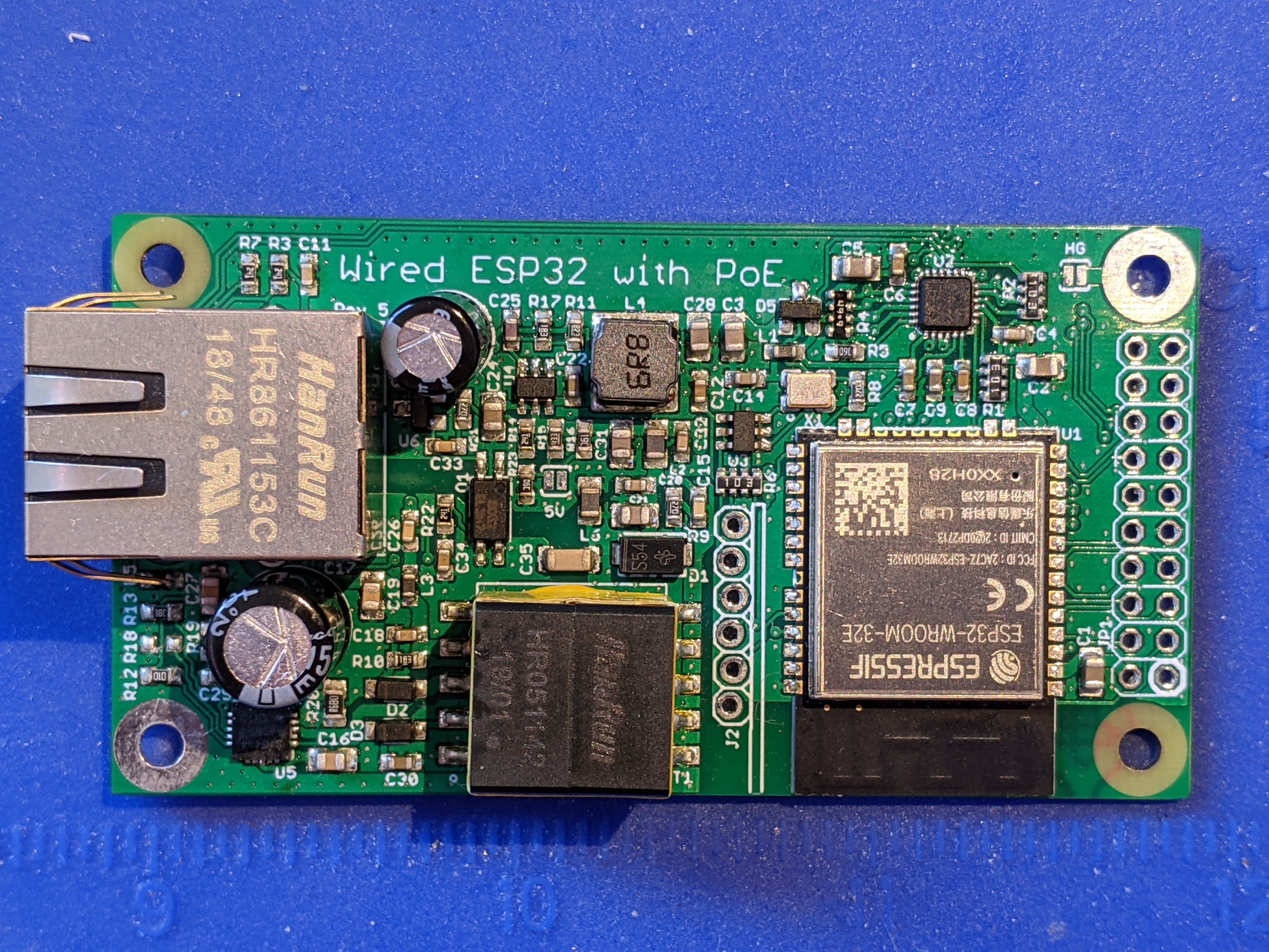
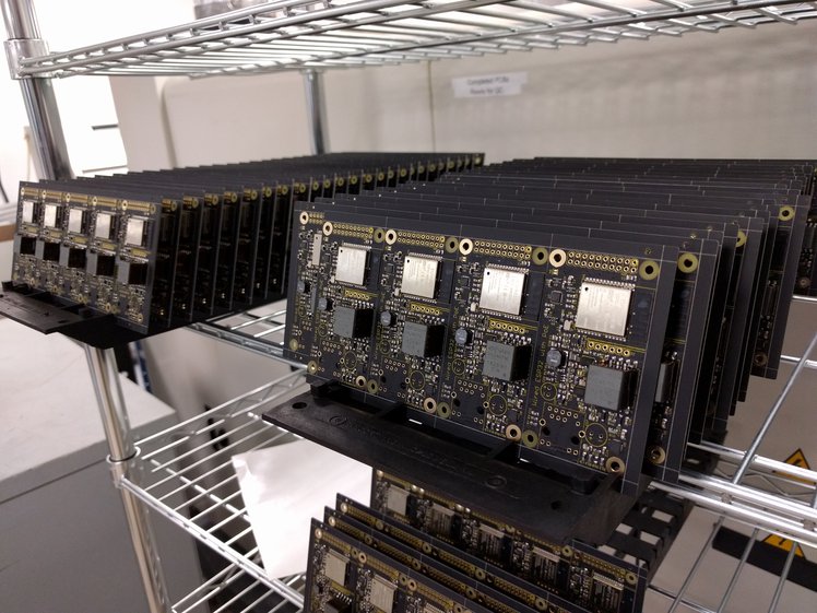
    So we spent most of this week doing final assembly (installation of two through-hole electrolytic capacitors and the Ethernet jacks) and testing for all 245 boards in the first batch. I am quite pleased with the result, I hope you backers will be happy as well!

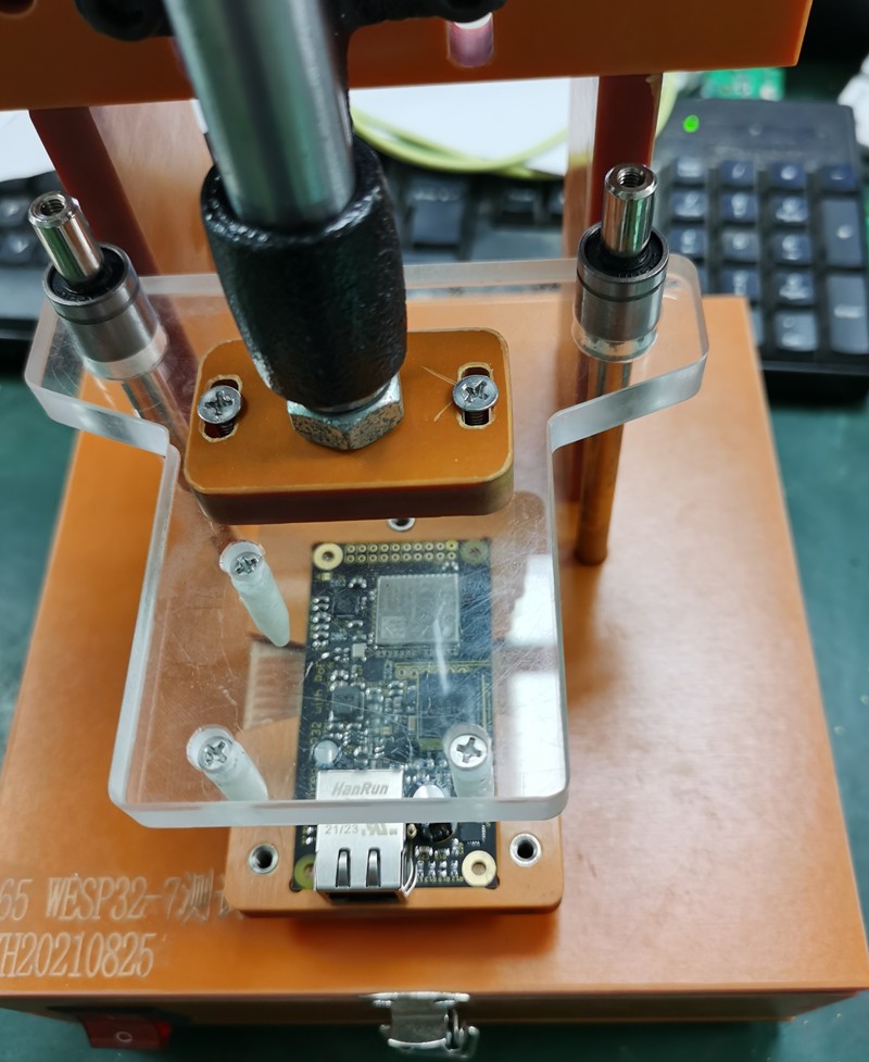
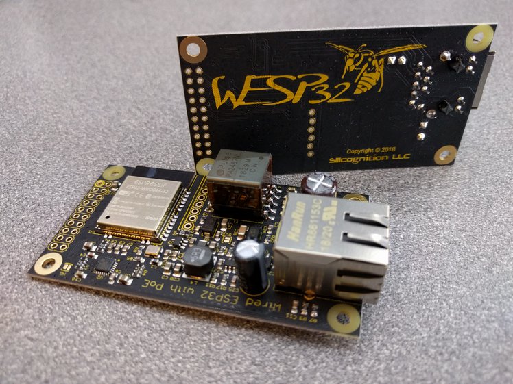
    Some boards were used for internal testing, some had to be sent back to Colorado Tech Shop for rework after finding issues during test, but today we were able to ship the first 205 units to Crowd Supply for delivery to backers next week.

    One of the boards was used for an experiment. I wanted to see if the board worked with the AI-Thinker ESP32-S module instead of the ESP32-WROOM-32:

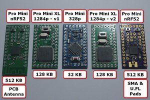
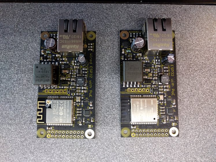
    I’m happy to report it seems to work just the same, so this module could be used to provide a future U.FL antenna connector option!
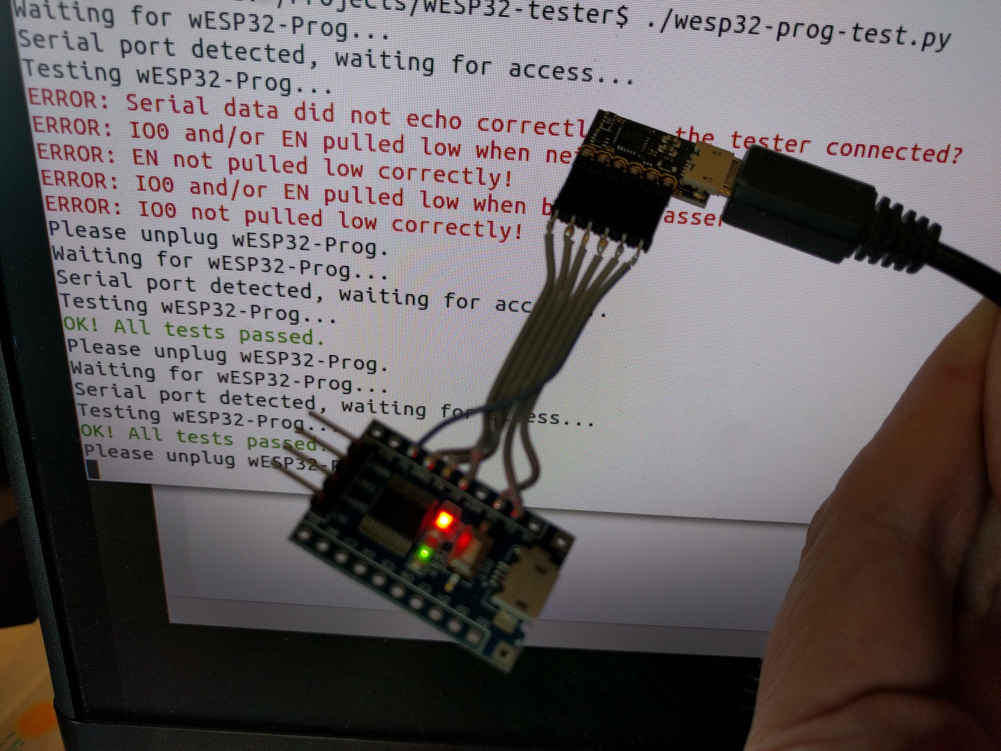
  • Production update, and testers!

    Patrick Van Oosterwijck12/30/2018 at 06:39 0 comments

    Last week it dawned on me that time keeps passing and I hadn't given much thought yet to how I was going to test the wESP32 and wESP32-Prog boards before we ship them!  A very important issue to start cranking on, especially with holidays and vacation eating up a good amount of time.

    wESP32-Prog tester

    The wESP32-Prog board is quite simple and because of this, the tester can be simple as well.  Building the tester only took half a day and this is what I ended up with:

    The hardware consists of a little STM8S103F3 board that can be had for less than a dollar on AliExpress.  I had it laying around and all I needed for this was a simple UART capable chip, so this was perfect.  I used the Sduino project project to speed up firmware development.   It looks slightly different from normal Arduino code because the SDCC compiler doesn't support C++, only C.  It was simple enough to get it to work though, resulting in this code:

    // wESP32-Prog tester using STM8S103 board and sDuino
    
    #define IO0   PA1
    #define EN    PA2
    
    void setup() {
      // Initialize digital pin LED_BUILTIN as an output.
      pinMode(LED_BUILTIN, OUTPUT);
      digitalWrite(LED_BUILTIN, 1);
      // Initialize EN and IO0 test pins as input with pullup
      pinMode(IO0, INPUT_PULLUP);
      pinMode(EN, INPUT_PULLUP);
        // Init serial port to 115200 bps
      Serial_begin(115200);
    }
    
    void loop() {
      // Read a byte from serial port
      int c = Serial_read();
      // Did we get a byte?
      if (c >= 0) {
        // Set lowest bit to value of IO0
        c = (c & 0xFE) | (digitalRead(IO0) ? 0x01 : 0);
        // Set second lowest bit to value of EN
        c = (c & 0xFD) | (digitalRead(EN) ? 0x02 : 0);
        // Echo byte back with altered IO0 and EN bits
        Serial_write(c);
        // Set the green LED state according to the second highest bit
        digitalWrite(LED_BUILTIN, (c & 0x40) ? 0 : 1);
      }
    }

     All this does is when a byte comes in, echo it back with the bottom two bits replaced by the current state of the IO0 and EN signals.  The second to highest bit also sets the tester board's on-board LED state.

    This firmware works in conjunction with a little Python script on my Linux box:

    #!/usr/bin/env python3
    
    import os
    import glob
    import serial
    import time
    from termcolor import colored
    
    while True:
    
      print("Waiting for wESP32-Prog...")
        ports = []
      while not ports:
        ports = glob.glob('/dev/ttyUSB*')
        time.sleep(0.1)
    
      print("Serial port detected, waiting for access...")
        while (not os.access(ports[0], os.R_OK|os.W_OK)):
        time.sleep(0.1)
        print("Testing wESP32-Prog...")
        test_ok = True
      s = serial.Serial(port=ports[0], baudrate=115200, timeout=0.1)
    
      s.setRTS(False)
      s.setDTR(False)
      s.write(b'0')
      res = s.read(1)
      if (res not in [b'0', b'1', b'2', b'3']):
        print(colored("ERROR: Serial data did not echo correctly, is the tester connected?", 'red'))
        test_ok = False
      if (res != b'3'):
        print(colored("ERROR: IO0 and/or EN pulled low when neither is asserted!", 'red'))
        test_ok = False
    
      s.setRTS(True)
      s.write(b'0')
      if (s.read(1) != b'1'):
        print(colored("ERROR: EN not pulled low correctly!", 'red'))
        test_ok = False
    
      s.setDTR(True)
      s.write(b'0')
      if (s.read(1) != b'3'):
        print(colored("ERROR: IO0 and/or EN pulled low when both are asserted!", 'red'))
        test_ok = False
    
      s.setRTS(False)
      s.write(b'0')
      if (s.read(1) != b'2'):
        print(colored("ERROR: IO0 not pulled low correctly!", 'red'))
        test_ok = False
    
      if (test_ok):
        print(colored("OK! All tests passed.", 'green'))
        s.write(b'@')
    
      s.close()
      print("Please unplug wESP32-Prog.")
        while ports:
        ports = glob.glob('/dev/ttyUSB*')
        time.sleep(0.1)

     What this does is wait for the wESP32-Prog board to be plugged in, which will create a /dev/ttyUSB0 device.  For some reason, trying to immediately open the serial device after this threw an access error, so we wait until it becomes accessible and then open it.

    Testing ensures that when we send a byte, the STM8 micro echoes a (modified) byte back to us.  We do this with various states of the RTS and DTR signals which control...

    Read more »

View all 29 project logs

Enjoy this project?

Share

Discussions

Barry Parr wrote 03/28/2019 at 00:30 point

In regard to the potential for taking out the PHY , Have you considered putting 50..100 Ohm series resistors on some of the IO ?

  Are you sure? yes | no

Patrick Van Oosterwijck wrote 05/10/2019 at 18:17 point

I have considered it but not had the chance to experiment with it yet.  I need to find out exactly what breaks when the PHY dies, which I'm not sure how to do.  Any ideas?  I may have trouble finding room on the board for them too, considering how dense it is...

  Are you sure? yes | no

Barry Parr wrote 05/10/2019 at 22:08 point

The drive/sink current of a lot of pins on the esp32 is in excess of 20mA.

RXD1/0 of the lan8720 is 8mA so perhaps it's RXD0/1 that gets cooked when an input gets turned into an output accidentally . 3v3 / 8mA >> 412  . 470 Ohm series on those two might cover it . I have seen a few designs that have only 10 Ohm series on those pins .

  Are you sure? yes | no

Samuel Archibald wrote 03/27/2019 at 17:14 point

Are you able to use a SSL/TLS connection, and if so, does the ESP handle it as gracefully as it does on Wi-Fi?

  Are you sure? yes | no

Patrick Van Oosterwijck wrote 05/10/2019 at 18:18 point

Hi Samuel, sorry for the late response.  Yes, SSL/TLS works as gracefully over Ethernet as it does over WiFi!

  Are you sure? yes | no

drewsed wrote 12/30/2019 at 03:00 point

What is a good way to jse TLS? Is it possible with Arduino? Or is it better with ESP-IDF?

  Are you sure? yes | no

2Fast2BCn wrote 01/14/2019 at 09:08 point

Unfortunately this stuff doesn't fit into an EU wall box. I'm going to assume you can remove the female RJ45 jack and solder the Ethernet cable directly onto the board but I'm afraid even then it will be to long. Why aren't these boards made more rectangular?

  Are you sure? yes | no

Patrick Van Oosterwijck wrote 01/16/2019 at 16:38 point

Sorry, but when dealing with isolated power conversion and big parts like the flyback transformer and ESP32 module, there are limitations to how things can fall into place and still fit in a rectangular shape.

The RJ45 cannot be removed, it contains the Ethernet magnetics for data path isolation and the diode bridges for PoE power extraction.

The boards _are_ rectangular, I'm not sure what you mean with "more rectangular".  Do you mean more square?  What dimension change would make it fit in an EU wall box?

  Are you sure? yes | no

2Fast2BCn wrote 01/16/2019 at 22:15 point

Yes, more square. Sorry, English is not my native language.

What I was fishing for is that 55mm x 55mm would just fit in my wall box if the Ethernet connection is inward (or no RJ45 socket). I understand it's outward to allow for a case but in the wall it only hinders?

wESP32 could make for a killer room presence detection with the Bluetooth and also make all my switches smart.

  Are you sure? yes | no

Patrick Van Oosterwijck wrote 03/11/2019 at 16:05 point

I wanted to mention that I am "thinking about" a wESP32 Mini, so maybe in the future I'll have something that fits your need.  As technology moves forward, new parts become available, and a new part from TI just caught my attention that does the flyback converter feedback through the auxiliary winding, removing the need for some secondary components such as the opto-coupler and reference.

I just need to find some time to play with them. :)

Also, no worries about hijacking the conversation piprog, you are providing relevant information. :)

  Are you sure? yes | no

piprog wrote 01/17/2019 at 22:46 point

You might want to check out the Shelly 1 - it is exactly for automating traditional switches (although wirelessly) and should fit in an European wall box. Works with Tasmota and thus with HA. I would LOVE if it were Ethernet + PoE, but I haven't found such a thing yet.  (Patrick: I'm sorry for hijacking the conversation but I feel it is relevant)

  Are you sure? yes | no

2Fast2BCn wrote 01/18/2019 at 09:04 point

Hello, Thanks for the suggestion. I have CAT5 running to all my toggle switches. I'm aware of the Shelly 1. A LOLIN D32 combined with a passive POE injector is cheaper and provides me with more flexibility. Unfortunately those are all wifi only and in my experience wireless networks work 99% of the time. So I prefer the 100% of Ethernet for a 100% wife approval factor ;-) because 99% is equal to 50% in Wife approval factor therms ;-)

  Are you sure? yes | no

piprog wrote 12/17/2018 at 12:08 point

Hi Patrick - excellent idea! I'd like to build a DIY HA/Security multisensor (like this: https://www.youtube.com/watch?v=jpjfVc-9IrQ). For this Ethernet+PoE makes much more sense (security) and I also have the cabling in the wall:), but the current price per unit is prohibitive for me. The above assembly is $15 all included, based on a $2.52 NodeMCU module. I'd need around 15-20 units and the price difference adds up quickly. How do you see, is there any chance this could go down in the $10s range anytime soon (like end of next year)?  (I understand that this is a custom project with very low volume and there are startup costs to be recovered, etc.) You could probably cooperate with one of the Chinese manufacturers to take over the assembly and pay you royalty (I know, can be shady) - e.g. the Sonoff guys could be one good candidate... I'm sure there would be ample demand if the price is right.

  Are you sure? yes | no

Patrick Van Oosterwijck wrote 12/30/2018 at 06:06 point

Yeah that's the hard part.  The cost of the ESP32 module is pretty much irrelevant to the total cost at the moment.  The PoE parts are the biggest cost adder, so I'm not seeing this end up being in $10 range any time soon.
I do intend to get this produced in China in the long run, but I need to find a good CM first.  My first try with Boktech wasn't successful unfortunately.

  Are you sure? yes | no

Vipul Garg wrote 12/03/2018 at 14:35 point

Is the hardware is open source, if it is then where i can find pcb files 

  Are you sure? yes | no

kesh27 wrote 10/24/2018 at 18:10 point

How are you hoping production would look after the crowd supply campaign is finished?  I got in early on the campaign for half a dozen to experiment with for campus/dc monitors. If cost and volume numbers are good, we would be interested in 50-100 units and I'm curious how that might look in the new year?

  Are you sure? yes | no

Patrick Van Oosterwijck wrote 10/24/2018 at 18:30 point

I will definitely keep producing these after the campaign.  The campaign is just to get eyeballs and get them in people's hands to start designing, but I'm expecting this to be more of a B2B / bulk product once people have designed something with them and put it in production.

I'm keeping an eye on orders and will soon be starting procurement for the next batch, which I expect could be produced by late December / early 2019.

  Are you sure? yes | no

aloismbutura wrote 09/16/2018 at 14:25 point

I just subscribed to your crowd supply campaign. My slight request is on the footprint. The WROVER and WROOM32 have compatible footprints on a PCB. Check the REV4 of the ESP32 devkit-c. This will allow upgrading of the ESP32 module on the board or even offering the WROVER as a different tier on the campaign due to the larger RAM/SPI flash benefits.

  Are you sure? yes | no

Patrick Van Oosterwijck wrote 09/16/2018 at 18:22 point

Unfortunately my layout is really dense to try and keep the board as small as possible, so there's no extra room on my board to accommodate the larger WROVER module.

  Are you sure? yes | no

Emanuele Tessore wrote 09/12/2018 at 16:06 point

Hi there, this is great stuff! I'll use it to convert my light switches to smart switches and eventually drop a bunch of sensors inside and outside my home!

Have you tried any sort of remote programming on this board? for example TFTP or, even better, network boot.

  Are you sure? yes | no

Patrick Van Oosterwijck wrote 09/12/2018 at 16:28 point

I've been amazed at what functionality is already available in some of the software frameworks that exist for the ESP32.  That said, I'm more of a hardware guy myself than software or application, so I'm very interested in what OTHERS will be able to cook up with these boards. :)

  Are you sure? yes | no

Emanuele Tessore wrote 09/12/2018 at 17:48 point

Thank you so much for beeing an hardware guy, cause I've tried to wire route a simple flip-flop button debouncer with some bad results :D.

I can't wait to have a couple of these on hand :) First of all I'll try to make a light switch that uses no mains power and comunicats to a central server (something like a Raspberry) where some logic decide the light to be turned on or off... 

I've a proof of concept running on an ATmega328P (Arduino) but I'm stuck on finding a board small enought to be mounted inside the electrical box and with a decent amount of memory and wired network. 

Your board will also save me from wiring all the boxes with a low voltage CC line :) Best of all this board will probably save me from using some (very pricy) KNX devices.

So I'll need a sample of 3 boards for development and if everything on my side works a grater batch (maybe 50 pieces) in something like 6 months... Are you planning to have some future run or make these boards available on demand in reasonably small batches?

Thank you, again :) Cheers

  Are you sure? yes | no

Patrick Van Oosterwijck wrote 09/12/2018 at 18:25 point

Yes, the Crowd Supply campaign is just to get as many boards as possible into the market quickly and to establish demand. Later they will be available for sale through various channels including Tindie.

  Are you sure? yes | no

CLQ wrote 09/07/2018 at 09:33 point

Hi everyone,

It's really an awesome project. 

Have you planned to share the software ? Did you used ISP-EDF or somethong else (ESP-Arduino, so on) ?

  Are you sure? yes | no

Patrick Van Oosterwijck wrote 09/12/2018 at 16:26 point

I hope to have broad software support.  I've tested with ISP-IDF, Arduino, Lua-RTOS-ESP32 and MicroPython up till now.  I have pull requests in to upstream board support in arduino-esp32 (https://github.com/espressif/arduino-esp32/pull/1821) and Lua-RTOS-ESP32 (https://github.com/whitecatboard/Lua-RTOS-ESP32/pull/192).  They are very easy merges but up till now they haven't been pulled in yet, so if you can add your voices to those projects to have them pulled in that would be helpful. :)

  Are you sure? yes | no

fabian wrote 09/01/2018 at 17:55 point

ideal for tor server. Plug in bibliotek or other place and increase tor network speed and anonimity

  Are you sure? yes | no

martinschki wrote 08/27/2018 at 18:04 point

Great Project!!

Looking for something like that for a loooong time!!!

I want to use these as room controller with a BME280 and a light sensor. Nothing fancy at all. Just sending sensor data every couple of seconds to a MQTT server.

They will go into a wall so my only concern and also question is: How much heat do they emit under such a low power application?? 

Since the sensors basically cover the hole they are put into it would impact the measurements...

Thanks! 

  Are you sure? yes | no

Patrick Van Oosterwijck wrote 08/31/2018 at 18:44 point

Thanks Martin!

I quickly did a test under low load and put a thermal image up so you can check it out, it's in this project log: https://hackaday.io/project/85389-wesp32-wired-esp32-with-ethernet-and-poe/log/152108-coming-to-crowd-supply

  Are you sure? yes | no

martinschki wrote 09/20/2018 at 08:53 point

thank you Patrick, looking forward to your campaign 

  Are you sure? yes | no

Sheepinator wrote 08/22/2018 at 03:48 point

Excellent project and something I've been looking after for quite some time.

If you had to, what SoC would you use to get just ethernet and none of the wifi. (Consider an industrial application with RF restrictions.)

Thanks!

  Are you sure? yes | no

Patrick Van Oosterwijck wrote 08/31/2018 at 17:40 point

I haven't really given it much thought to be honest, and I tend to spend a lot of time on component selection, so I would take a while to figure it out. :)  I'd probably start by looking at Cortex-M4's and Cortex-M7's from ST and NXP.  Any SoC you would recommend?

  Are you sure? yes | no

Mikhail wrote 08/21/2018 at 07:47 point

Thanks for your great project, Patrick!

Comment:

Personally I don't like ESP32-WROOM module and do prefer ESP32-PICO-D4  with a 3D antenna for better Wi-Fi connection and lower overall power consumption, but it will make a board a lot more complicated, so that's not an real issue now for PoE solution, just a wish.

Question:

As I see now your project is close to prototype completion, so any estimates now for release date and production costs for small quantities? (~100pcs batches after initial evaluation) 

  Are you sure? yes | no

Patrick Van Oosterwijck wrote 08/21/2018 at 17:41 point

I use the ESP32-WROOM because it has modular FCC certification, which I wouldn't get if I did my own antenna.  Likely the WiFi won't be used on this board in most cases, but I am interested in the Bluetooth functionality as it can make this a useful Bluetooth sensor aggregator / hub.

I have parts for a 240 piece batch on order, and am talking to Crowd Supply to do another campaign like the one I'm running for the #LiFePO4wered/Pi+ right now (https://www.crowdsupply.com/silicognition/lifepo4wered-pi-plus).

  Are you sure? yes | no

Mikhail wrote 08/21/2018 at 21:41 point

Don't really care about certification - still need to recertify everything for production devices, at least where I am (Russia).

OK, count on me as very interested for samples and maybe larger quantities. It will depend on price and performance vs our current prototypes that are made using  PoE splitter and Ethernet module add-ons.

Personally I do like using Bluetooth for connecting speakers to ESP32. (just sharing an idea)

  Are you sure? yes | no

John wrote 08/21/2018 at 07:13 point

This is really awesome, Patrick! I am looking forward to get a few of these boards when they are available!  I'm trying to learn more about how PoE works and was wondering why you decided to use a RJ45 jack with a bridge rectifier and an external transformer over an RJ45 jack with a built in transformer and an external bridge rectifier. Excuse my noob-question on this. Still at baby steps in understanding PoE. Thanks

  Are you sure? yes | no

Patrick Van Oosterwijck wrote 08/21/2018 at 17:35 point

Thanks John!  The RJ45 jack does contain the Ethernet magnetics ("transformers") for the data path.  The external transformer is for PoE power conversion only, and as far as I'm aware, nobody produces an RJ45 jack with this power transformer integrated.  It wouldn't make sense to do this since a lot of circuitry is involved (all the circuitry between the RJ45 and flyback transformer).

The jack I use integrates the PoE diode bridges in addition to the Ethernet magnetics, which is nice because these bridges tend to take up a lot of PCB space.

  Are you sure? yes | no

John wrote 08/22/2018 at 13:53 point

Thanks for the reply. Ah! Now I understand. I got confused about the power transformer and thought this was the ethernet magnetics.

Follow up question on ethernet jacks. Did I get this correct that the jack you use uses all 4 pairs for power, and two pairs are data? If so, the PHY only uses one pair for data? I am trying to understand how some hobbyists may just split open an RJ45 cable and add 12v to it, and what that might result in. Sorry again for the noob-question.

  Are you sure? yes | no

Patrick Van Oosterwijck wrote 08/22/2018 at 16:42 point

The phy uses two pairs for data.  For IEEE 802.3at compliant PoE, the power can either be on the same pairs as the data, or it can be on the spare pairs, so the Ethernet jack contains two diode bridges to cover both cases.

The DIY 12V or "passive PoE" are not standard compliant and not supported by the wESP32.

  Are you sure? yes | no

timonsku wrote 08/19/2018 at 22:22 point

Great stuff! I really miss Ethernet with all these modern MCUs, even if they support it natively, barely anyone makes boards that support it.
Will you sell it afterwards? This would definitely be interesting for some work projects.

  Are you sure? yes | no

Patrick Van Oosterwijck wrote 08/20/2018 at 05:24 point

Yes!  As all major systems have been checked out and I'm very satisfied with the performance of the design, getting to production is being worked on right now! :)

  Are you sure? yes | no

timonsku wrote 08/20/2018 at 12:22 point

Great! Do you have a price target yet?

  Are you sure? yes | no

[deleted]

[this comment has been deleted]

Patrick Van Oosterwijck wrote 08/20/2018 at 05:23 point

I moved it to the other side of the bead to make my layout easier. :)

Would it be "better" if this connection was on the other side of the bead?  Maybe.  Then you have to define "better".  Is the bead there to give the Ethernet signal path a cleaner power source, or to prevent switching noise from the Ethernet to get back to the 3V supply?  I don't know which they had in mind, probably both.  In the end, engineering is about compromises, and I would have had difficulties with my layout had I made these connections after the bead, so I decided to connect them to 3.3V instead.

The proof is in the pudding as they say and in this case "better" is probably just a matter of performance.  With 63 Mbit/s up and 55 Mbit/s down, I'm perfectly happy with the performance as it is. :)

  Are you sure? yes | no

K.C. Lee wrote 08/20/2018 at 12:59 point

You want to prevent digital noise getting into a long piece of Ethernet cable which can act as an antenna to the outside world.  i.e. keep the power clean at the Ethernet side.  So a LC filter would have the caps etc at the receiving side of the bead,  At least that's the way I would do it even if it means that I have to rip up all my nets and do another rounds of routing.  I don't settle at something that "works".

  Are you sure? yes | no

Patrick Van Oosterwijck wrote 08/20/2018 at 17:03 point

I agree 100%, but please check in the schematic what he's talking about first.  He's talking about the supply to the center taps of the secondary side signal transformers.

The power system connected to the primary (cable) side does have the recommended filter circuitry at the input (L3, L5, C26, C27).

  Are you sure? yes | no

SK wrote 07/29/2018 at 11:33 point

Hey there, very interesting project.
Olimex recently announced a similar board - ESP32-POE. There is no confirmation yet, but I am guessing they will release it as an OSHW design (all their other ESP32 boards are OSHW):
https://olimex.wordpress.com/2018/07/25/new-esp32-board-teaser-power-over-ethernet-esp32-poe-is-perfect-for-sensors-using-existing-ethernet-wiring/

  Are you sure? yes | no

Patrick Van Oosterwijck wrote 08/16/2018 at 20:09 point

Yeah, I saw that, and at first I thought: "With competition from such a known player I might as well shelve this project".  But then I looked at the info that was available and noticed:

- There's no flyback transformer which means their design provides no isolation as required by the IEEE 802.3af/at PoE specification.  Prototyping will be fine but actual installations with long wire runs in buildings will likely be troublesome.

- I haven't seen any specification on available output power.  The size of the inductor makes me think 12.95W as specified for IEEE 802.3at Type 1 is not attainable.

- It uses the CH340 for programming which is really undesirable.  My friend's Macbook got bricked by trying to install the driver for this device.

All of this (especially the first point) puts their device firmly in the hobbyist category.  I'm under no illusion that this still represents stiff competition as their price will be better than mine and most people will hear about theirs and not mine, but I'm hoping there will be a niche for me when people are looking at professional deployments that are IEEE 802.3at compliant.

  Are you sure? yes | no

hennie.tempelman wrote 07/07/2018 at 21:22 point

Hi Patrick, really great project.

For years I have been using the Propox Wiznet module with ATMEGA128A and Ethernet. Very much like the AVR-Studio. I work in industrial automation (gas turbines); I even implemented the Siemens S7 protocol on my AVR and now can do great stuff such as native peer comms and talking to a DDE/OPC server. This gives me great 'eyes' to my projects.

But time moves on. Got myself an ARM board (Atmel SAM D20) because everybody says you should be 32 bit; with this I would be able to use Studio for that too. But I couldn't really see the benefit of moving to 32 bit 'just because', so it grinded to a halt.

Then recently I did get kind of stuck. I want to make a weather station (based on a recent Elektor design), but with my good-old Wiznet. But pulling yet another Ethernet cable... A Wifi add-on for the ATMEGA seems expensive and clumsy. And the ESP32 has it all out of the box, and so much more. And oh-yes, it is 32 bit and amazing clock speeds - thus future proof. And cheap.

But... Wifi is fine for a weather station. But not for important stuff such as domotics, machine automation and what else. But with the standard ESP32 solutions on the market I was now loosing my Ethernet. Except for some poor Olimex designs (too bulky for integration).

Then I found your project. I think it is almost perfect, and I totally agree with all your considerations. I think the initial price you have in mind is just fine; I pay a similar price for the Propox module and that never stopped me.

So when you have some for sale; I'd be happy to buy a few to try and use in my next projects.

I have a question: Can the module also be powered WITHOUT POE? (i.e. will it merrily accept 3.3 V or 5 V on the power pins?) I guess yes, but asking to be sure.

I also have another question (to you or others): would I be able to use my favoured AVR-Studio still with an ESP32 signature file or so? If not, what similar environment would you recommend. Whilst I do a lot with AVRs, I never had a go at Arduinos (and don't really want to either), so I am not familiar with that environment .

And 'if' you consider a redesign, then I'd suggest to make a DIP-style pinning. This is easier for use on a breadboard (as double pin rows cause a short). And on a final product you achieve mounting stability without any need for screws and such. Just check the Propox module (and others) as example.

Thanks - Hennie.

  Are you sure? yes | no

Patrick Van Oosterwijck wrote 07/28/2018 at 03:15 point

Hello Hennie,

Thanks for your kind words! :)  Here are some answers to your questions:

- Yes, you can supply power to the V+ pin or, if the ESP32-Prog module is installed, it can power the ESP32 over USB.

- I have no idea if you can program an ESP32 from AVR Studio, I would assume not but I don't know how flexible it is.  Not a fan of Arduino myself, I consider it yesterday's cool way of doing things and behind the times.  For C you can do ESP-IDF and MongooseOS, Espruino and MicroPython work well too for higher level development.  PlatformIO provides a nice environment as well.  Anything's better than Arduino. ;)

- DIP-style: I was considering this at some point but someone else said dual row header was what they preferred and it was the only feedback I got at the time.  In hindsight, it was the better option as well to be able to do the really dense layout to keep it small.  There are ribbon cable header to breadboard adapters in the market that should work.  I agree prototyping concerns are important, and there should be solutions provided even if they take some extra parts, but this project is mostly production optimized for people who want to use it in the field.

  Are you sure? yes | no

Giovanni wrote 06/10/2018 at 23:27 point

Hi Patrick, great project! 

Quick question - will there be 5V available from the board along with 3.3V for powering external components? That would be very handy!

BTW Did you think of starting a small Kickstarter or Indiegogo campaign? I know this is quite a niche project so perhaps the audience will be limited but on the other hand you may not need that much money to complete it either.

  Are you sure? yes | no

Patrick Van Oosterwijck wrote 06/11/2018 at 11:23 point

By default there is 12V and 3.3V available.  But I included a solder jumper to switch from 12V to 5V on the power output.  Total output power will likely be less when configured to 5V compared to 12V since the flyback turns ratio is optimized for 12V.  You can of course do your own conversion from 12V to 5V as well.

Doing a campaign is definitely on the table.  First need to confirm everything works though. :)

  Are you sure? yes | no

Andreas wrote 05/26/2018 at 09:25 point

Hi Patrick, - I like your thoughts on PoE with ESP32 because I am looking for a way to replace a working door lock system for 30 doors in one building that I designed in about 2008 (together with an EE) that still works well but so far, it's a prototype. Technology has moved on since then.

I am choosing the ESP32 now because it seems to be the only small, affordable microcontroller out there capable of a decent encryption (AES etc.). Wifi does not make sense for me because it can be blocked and might be unreliable. What I'd need as an adaption of the WESP32 that connects a numerical keyboard (we can manufacture that here, inox steel for outside), three LEDs and a relay to open a door opener magnet. The 12 V version of PoE seems fine to me, but I'd have more questions. Would you be available for some questions? I could not find an email address so far. My website is dellekom.de and I am thinking of sponsoring your development of the WESP32 if this is still on the table :) - and then we could talk about paid modifications..

Andreas

  Are you sure? yes | no

Patrick Van Oosterwijck wrote 06/11/2018 at 09:57 point

Hello Andreas,

Sorry I didn't see this sooner, Hackaday.io seems to be very flaky about sending comment notifications.  Sometimes it does, sometimes it doesn't.  I haven't found any logic in it yet.

Your application looks perfect for something like this!  We can discuss your questions over email and I am certainly interested in your sponsoring offer! :)  I'll shoot you an email.

Patrick

  Are you sure? yes | no

Similar Projects

Does this project spark your interest?

Become a member to follow this project and never miss any updates