 Dave Gönner
Logs:
1. Overview
2. D-type Flip-Flops
3. The Decoders
4. It's alive!
5. 2nd digit and RTC
6. Stuck... Unstuck... and redoing some work
7. Decoders continued...
8. Update June 2018
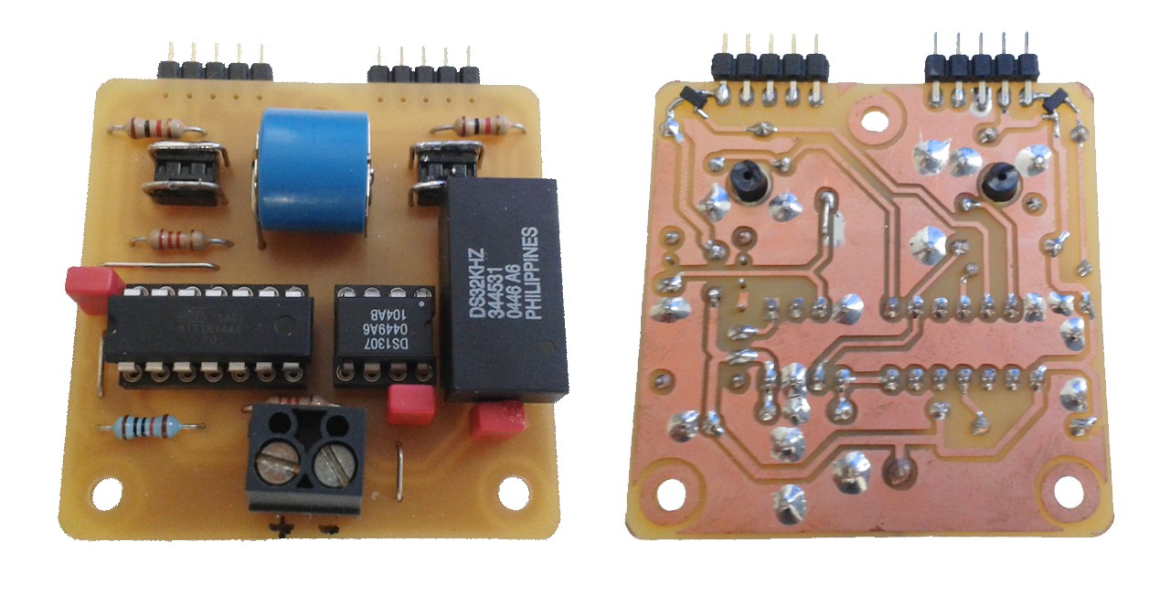
9. Timekeeping and RTC
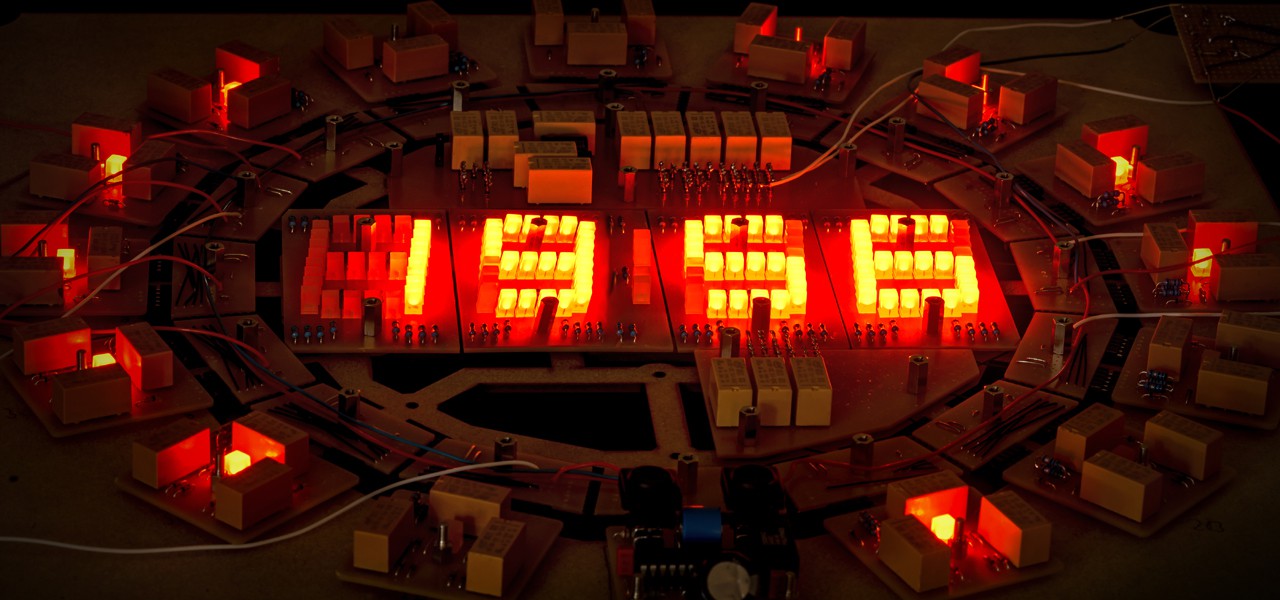
10. Foto update (Nov 2018)
11. It's finished!
0%
0%
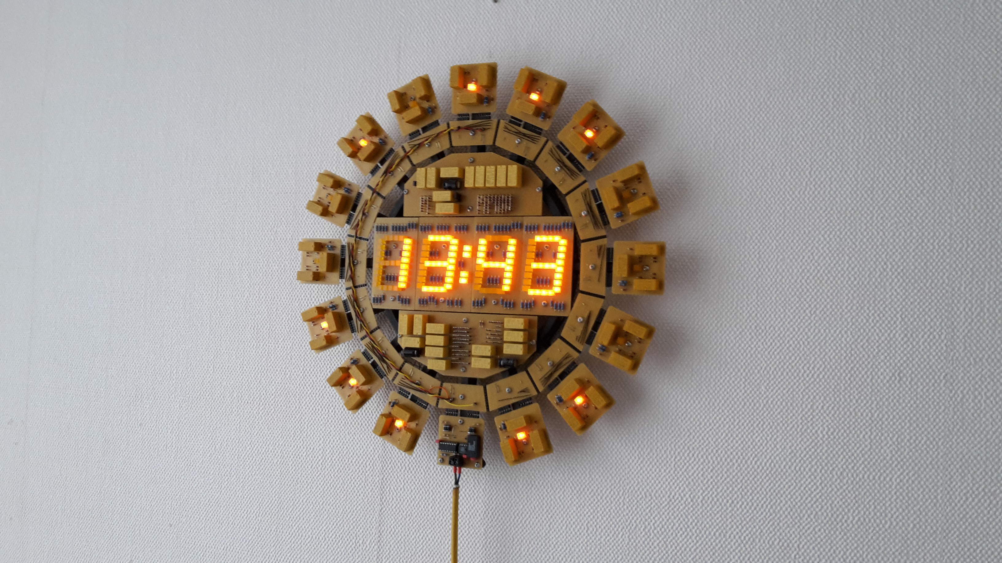
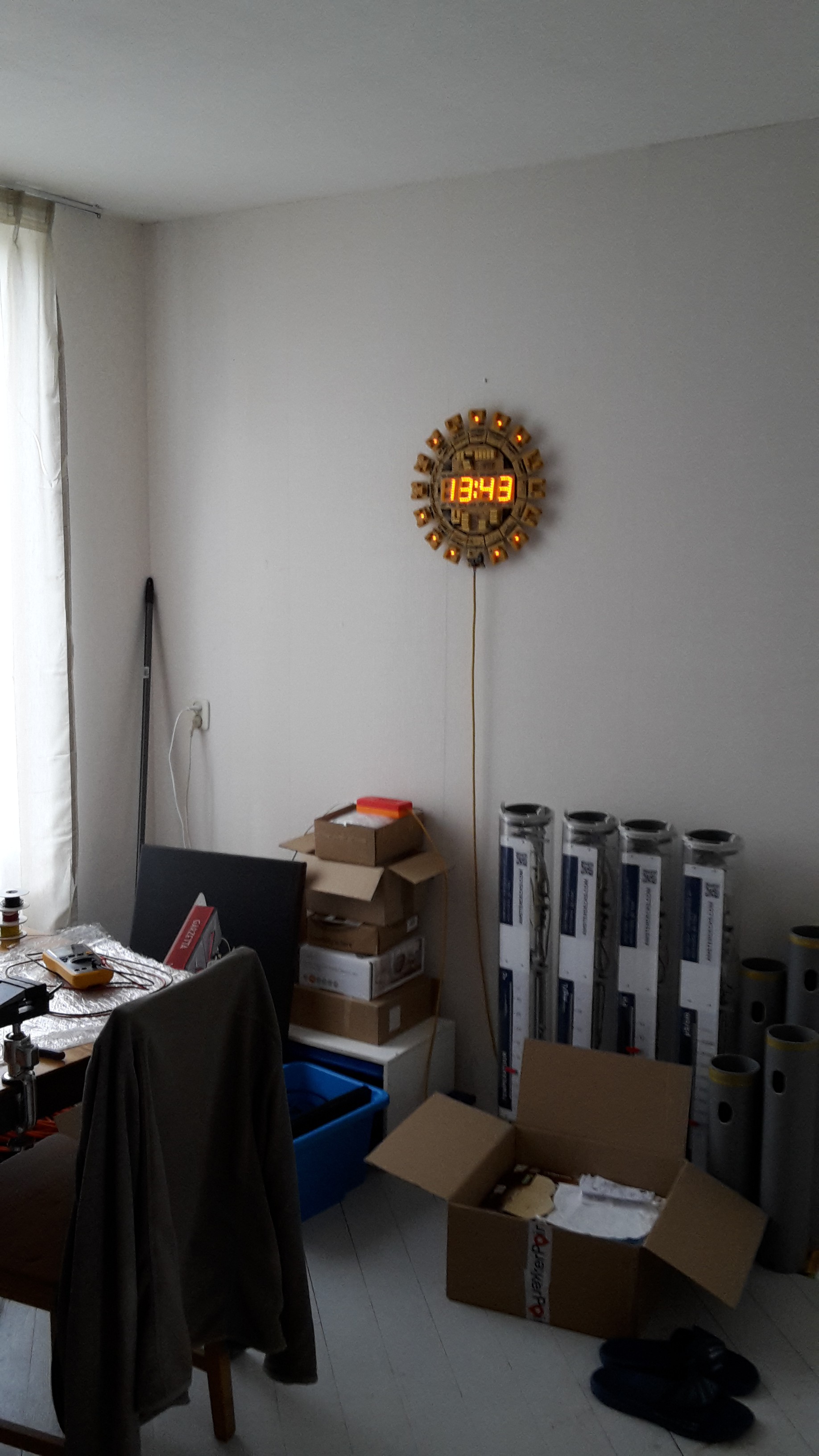
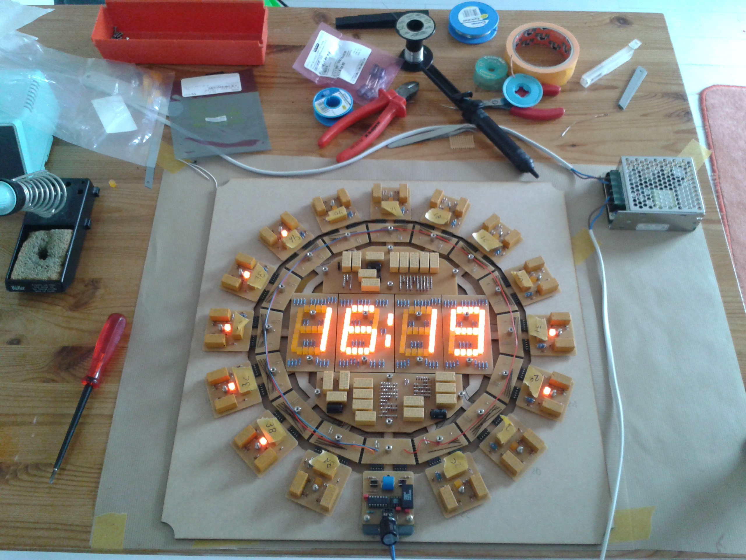
Relay Logic Clock
A digital 24 hour clock using only relays and diodes for the counting logic.
Become a Hackaday.io member
Already have an account? Log in.
Just one more thing
To make the experience fit your profile, pick a username and tell us what interests you.
Pick an awesome username
hackaday.io/
Your profile's URL: hackaday.io/username. Max 25 alphanumeric characters.
Pick a few interests
Projects that share your interests
People that share your interests


 Kris Slyka
 dic3jam
 Ken Yap
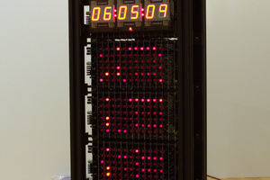
 Ted Yapo
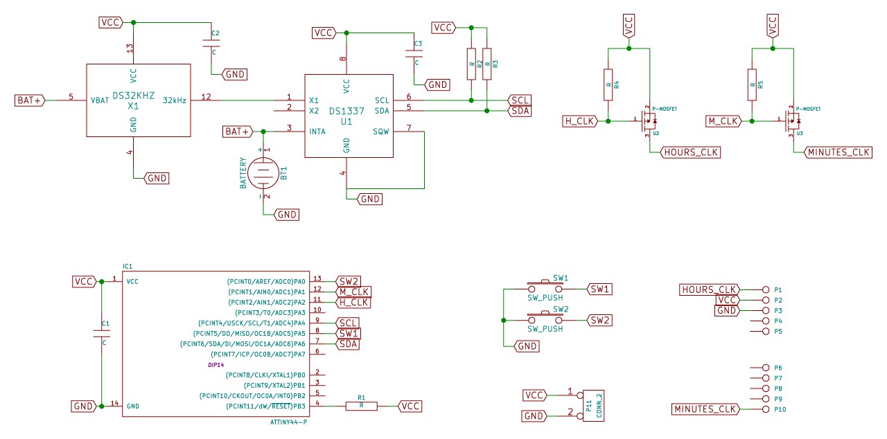
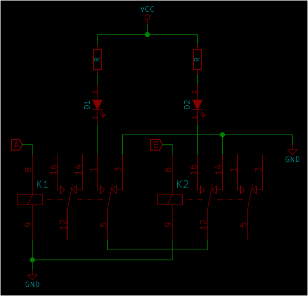
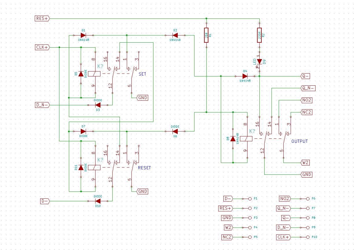
Someof your schematics are dark blue and dark red on a black background. This makes them very difficult to read.
Great project, I have always wanted to see someone actually use relay logic, but my eyes are killing me trying to read those schematics.