 Capt. Flatus O'Flaherty ☠
Licenses: Software: GPLv3; Hardware: Creative commons BY-SA.
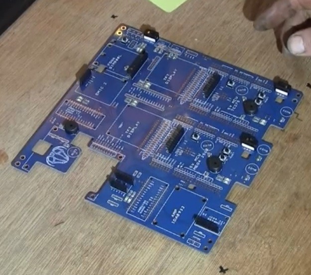
There's plenty of 'robot controllers' and such like out there such as Pixhawk for drones and ROS for more complicated robots, but how many have all the modules you need bolted onto one PCB with seamless integration via SPI and I2C? And what if you want to expand the capabilities? Is there any spare 'headroom', for example spare analogue in pins or SPI pins? Or spare space on the PCB? How many are based on just one CPU core with nasty latency issues? How easy is it to understand the code and dependency structure?
A lot of this project revolves around the use of a very fast 3 core processor, the TC275. This is the gadget that holds the world record (16 Mar 2018) for solving the Rubik's cube in something like 0.3 seconds ….. And it can be programmed using Arduino IDE!
Firstly, each core can communicate seamlessly with the others so, for example, core 0 could be controlling motors whilst core 1 sends and receives data to other modules such as the GPRS and TFT screens. The advantage is that core 0 can run at full speed and toggle digital output pins at very high speed (10 nano seconds), which is fast enough for most motors, particularly if servo 'gearing' is used.
If the code on core 0 is not too protracted, the core can run incredibly fast with lots of motors SMOOTHLY accelerating and decelerating. How many motors? I don't know exactly ...... Maybe as many as 20?
An agricultural robot has different requirements from the general run of the mill home vacuum romba. It requires super accurate GPS/GNSS - not just one unit, but two, enabling error correction between the two - one is static and the other roving. Next .... WIFI is a non starter so either cellular GPRS or satellite is required. Then there is debugging ..... We need loads of buzzers and LEDs - yes SERIOUSLY! These things are incredibly useful and obviously some kind of screen which is again incredibly useful for testing / commissioning ..... And what happens when the screen needs to refresh - it pauses the whole CPU core, so we need yet another core. We simply can not have enough cores and eventually the control system will have (about) 5 cores as we gradually upgrade the system within the dark corridors of GitHub.
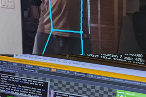
We're currently making rapid progress with Ai based object recognition and plan to spend the Winter working on perfecting techniques for creating models for detecting the crop itself and using it as the main source for navigation both along the rows and columns of plants. GPS will be used for general driving about the farm tasks. Springtime, we'll be starting to take photos of the crops and test the machine again, taking more and more photos as the season progresses, continually updating the system. At the end, we'll probably have about 10,000 photos to incorporate into the Ai model!
The overall plan is to market the control system using the actual WEEDINATOR as an example of what can be done rather than try and sell the whole machine. Much of the difficult work has been carried out in the background doing programming and the mechanical machine is the 'sexy' bit that attracts all the praise and adoration! Obviously we had to have the machine to test the controller, but the idea is that people are more likely to want to build their own mechanical machine to their own specs, but using our control system (hopefully).
 Nine months ago, the machine was using a Pixy2 camera to track barcode labels thrown down on the ground. The machine would steer towards the label and then stop dead when the barcode appeared at a pre-defined location on the x axis. Furthermore, the code revolves around calculating a simple 'panError' for the y axis, which is a slightly confusing name as it's not like a de-bugging error or such like. I'm going to change the name to 'deviance' for the future.
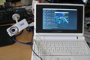
 Now to get data into the TC275 via the little Nano intermediator y and try some navigation tests.
 The Jetson TX2 developer board is fine for getting started, but really, I should have bought the TX2 Jetson module separately and bolted it straight to the Connecttech Orbitty carrier as shown above.
 Notes:


 rawe
rawe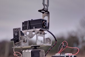
 Jerry Isdale
Awesome project ! I'm currently stuck with my own project because GPS errors are way too big then find this, great inspiration !
So in order to setup RTK GPS we only need :
Hardware
1/ 2 GPS modules at base and rover( in your project it was NEO M8P at rover and base)
2/ A way to communicate between base and rover (in your project it was SIM 800 GPRS)
Software
1/ A configuration file for U-center that you pointed out in step 8
2/ A GPS RTK library that handles numbers from base and rover to calculate the exact position (in your project it was NeoGPS from SlashDevin)
Is that enough ?
And could you please tell me what is the purpose of the configuration file for U-center ? Is it related to C94-MP8 module ?